CAS 750 Multi-Parameter Monitor Service Manual 2005 – PDF DOWNLOAD
Original price was: $75.00.$16.95Current price is: $16.95.
Official CAS Medical Systems CAS 750 service manual PDF from 2005 for multi-parameter monitors, covering introduction, safety, controls, configuration, maintenance, troubleshooting, service procedures, schematics, and parts. Includes CAS 750 troubleshooting guide, multi-parameter monitor battery replacement, NIBP calibration procedures, ECG respiration board service, CO2 calibration check, and SpO2 simulator tests for patient monitoring technicians.
Description
CAS 750 Multi-Parameter Monitor Service Manual 2005 – PDF DOWNLOAD
Description
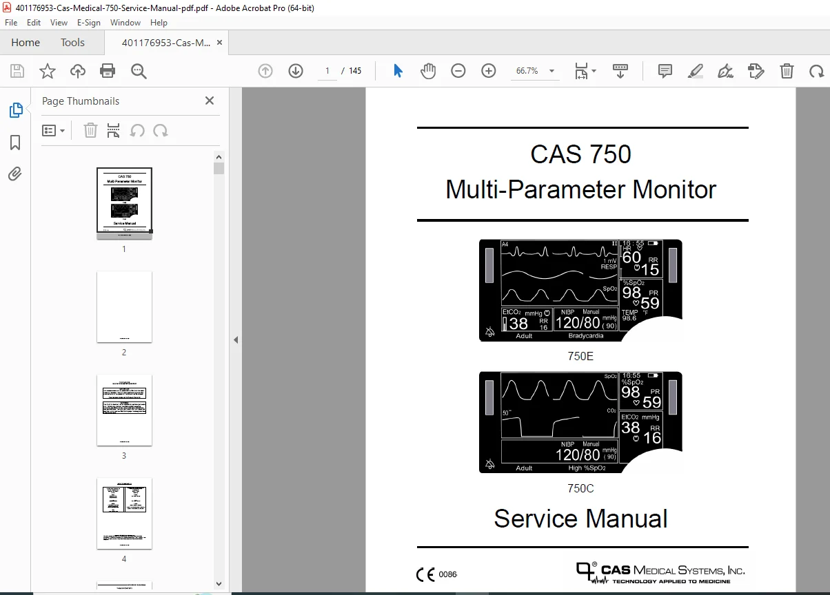
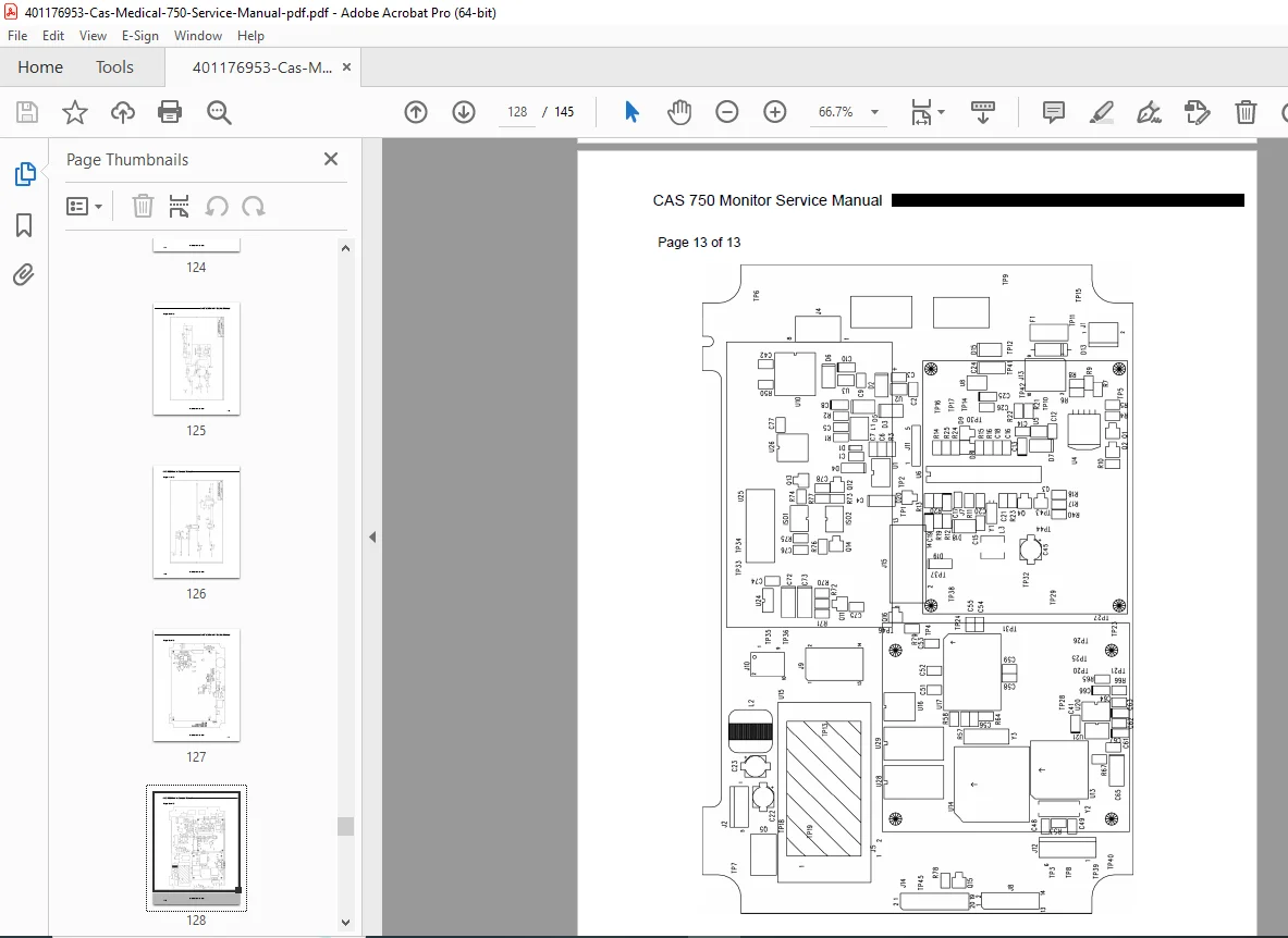
This CAS Medical Systems CAS 750 service manual PDF (21-02-0191, Rev. 00, December 2005) is a vital resource for qualified service personnel maintaining the CAS 750 multi-parameter patient monitor, including models 750E and 750C. It details device description, patient environment integration, manual overview, safety measures with automatic features, symbols, controls, setup menus, external interfacing, routine cleaning/maintenance, CAS 750 troubleshooting guide for user/monitor messages, maintenance procedures like battery charge and volume checks, service disassembly for boards (power supply, ECG/resp/temp, NIBP, SpO2, CO2, main control), schematics, and spare parts lists. Emphasizing warranty policy, repair returns, and electrical safety checks, it supports efficient multi-parameter monitor battery replacement, NIBP calibration procedures, and ECG respiration board service.
The manual warns of operation by qualified personnel only, with precautions for all parameters, even if not equipped. It includes CO2 calibration check, SpO2 simulator tests, and software versions verification for reliable cardiac/respiratory/NIBP/SpO2/EtCO2 monitoring.
Table of Contents
- 1. Introduction (Page 1)
- Introduction (Page 1)
- Brief Device Description (Page 1)
- Patient Environment (Page 2)
- Manual Information (Page 3)
- Revision History (Page 3)
- Manual Overview (Page 3)
- Intended Audience (Page 4)
- Definition of Terms (Page 4)
- Related Documents (Page 4)
- Monitor Configurations (Page 5)
- 750E Monitor Configurations (Table 2, Page 5)
- 750C Monitor Configurations (Table 3, Page 6)
- 2. Service Policy (Page 7)
- Warranty Policy (Page 7)
- Extended Warranty Program (Page 8)
- Returning the Monitor for Repair (Page 8)
- 3. Safety Measures and Warnings (Page 9)
- Automatic Safety Features (Page 14)
- 4. Declaration of Conformity (Page 15)
- 5. Symbols (Page 17)
- 6. Monitor Controls (Page 23)
- Front Panel (Page 23)
- Display Areas (Page 24)
- Main Display Area (Page 24)
- Time, Battery and Numerics (Page 25)
- Numerics and Temperature (Page 26)
- EtCO2 Numerics (Page 26)
- NIBP Numerics (Page 27)
- Patient Alarm Message Window (Page 27)
- Equipment Message Window (Page 27)
- Display Visual Indicators (Page 27)
- Front Panel Controls (Page 29)
- Display Areas (Page 24)
- Infrared (Ir) Data Port (Page 33)
- Rear Panel (Page 34)
- Battery Compartment (Page 35)
- External Device Interfacing (Page 35)
- AC / DC Connection (Page 35)
- Fuse Compartment (Page 35)
- Equipotentiality Ground Post (Page 35)
- Left Side View (Page 36)
- Cuff Hose Connection (Page 36)
- Temp Connector (Page 36)
- CO2 Sensor Connector (Page 37)
- SpO2 Sensor Connector (Page 37)
- ECG/Resp Connector (Page 37)
- CO2 Scavenger Exhaust Port (Page 37)
- Front Panel (Page 23)
- 7. Monitor Configuration (Page 39)
- Setup Menu (Page 39)
- Entering the Setup Menu (Page 39)
- Exit the Setup Menu (Page 40)
- Selecting the Language (Page 40)
- Selecting the Patient Mode (Page 40)
- Audio Alarm Silence (Silence/Reset Pushbutton) (Page 41)
- 2 Minute Audio Alarm Silence (Page 41)
- Permanent Audio Alarm Silence (Page 42)
- Setting the Date (Page 42)
- Setting the Time (Page 42)
- Daylight Saving Time Option (Page 43)
- Pacemaker Detection (Page 44)
- CVA Filter (Page 45)
- Set the SpO2 Alarm Delay (Page 45)
- End Tidal CO2 Units (Page 46)
- Selecting the Temperature Units (Page 46)
- Trace Background (Page 47)
- Setup Menu (Page 39)
- 8. External Device Interfacing (Page 49)
- Overview (Page 49)
- RS232 (Page 49)
- Nurse Call Interface (Page 49)
- DB9 Pin Out (Table 4, Page 50)
- 9. Routine Maintenance (Page 51)
- Cleaning (Page 51)
- Cleaning Overview (Page 51)
- The Monitor (Page 51)
- The Display (Page 52)
- Patient Cable and Leadwires (Page 52)
- Cuffs (Page 52)
- Tuff-Cuff® Reusable Cuffs (Page 52)
- Pedisphyg® Cuffs (Page 52)
- Pneumatic Tubing (Page 53)
- CO2 Consumables (Page 53)
- Printer (Page 53)
- SpO2 Sensors (Page 53)
- Temperature Probes (Page 53)
- Pneumatic Pressure Check (Page 54)
- Safety Checks (Page 54)
- System Checks (Page 54)
- Battery (Page 54)
- Cleaning (Page 51)
- 10. Troubleshooting (Page 55)
- System Troubleshooting (Page 55)
- Overall Block Diagram (Figure 13, Page 55)
- No Monitor Power (Figure 14, Page 56)
- Theory of Operation (Page 57)
- Power Supplies (Page 57)
- Battery Charger (Page 58)
- Supervisor Microcontroller (Page 58)
- Digital Signal Processor Controller (Page 59)
- User Messages (Page 61)
- ECG/Respiration User Messages (Page 61)
- SpO2 User Messages (Page 62)
- CO2 User Messages (Page 63)
- NIBP User Messages (Page 65)
- Monitor Messages (Table 5, Page 66)
- CO2 Monitor Messages (Table 6, Page 67)
- ECG/Respiration Monitor Messages (Table 7, Page 68)
- NIBP Monitor Messages (Table 8, Page 69)
- SpO2 Monitor Messages (Table 9, Page 71)
- System Troubleshooting (Page 55)
- 11. Maintenance Procedures (Page 73)
- Introduction (Page 73)
- Equipment Required (Page 73)
- Battery Charge (Page 74)
- Turning the Monitor “On” (Page 74)
- Verifying the Time (Page 75)
- Volume Checks (Page 75)
- Alarm Volume (Page 75)
- Beep Volume (Page 76)
- Service Menu Tests (Page 76)
- Entering the Service Menu (Page 77)
- Exit the Service Menu (Page 77)
- CO2 Calibration Check (Page 78)
- CO2 Calibration (Page 79)
- NIBP Calibration Check (Page 80)
- Manometer Pressure Check (Page 80)
- Overpressure (Page 81)
- Pneumatic Pressure Checks (Page 82)
- Plug Tube (Page 82)
- 500 ml Pressure Check (Page 83)
- +12 Volt Power Supply Check (Page 83)
- ECG/Respiration Calibration Check (Page 84)
- Temperature Calibration Check (Page 84)
- SpO2 Calibration Check (Page 85)
- SpO2 Simulator Check (Page 85)
- NIBP Simulator Check (Page 85)
- Software Versions (Table 10, Page 86)
- Electrical Safety Checks (Page 87)
- Leakage (Page 87)
- Hypot (Monitor) (Page 87)
- Hypot (SpO2) (Page 88)
- Data Sheet (Page 89)
- 12. Service Procedures (Page 91)
- Introduction (Page 91)
- Tools Required (Page 91)
- Replacing the Monitor Battery (Page 91)
- Removing the Battery (Page 92)
- Installing the Battery (Page 92)
- Changing the Fuses (Page 93)
- Outside Fuses (Page 93)
- Inside Fuse (Page 94)
- Main Monitor Service Procedures (Page 94)
- Prior to Disassembly (Page 94)
- Monitor Disassembly (Page 95)
- Monitor Assembly (Page 95)
- Replacing the Power Supply Board (Page 96)
- Replacing the ECG/Respiration/Temperature Board (Page 97)
- Replacing the NIBP Board (Page 98)
- Replacing the SpO2 Board (Page 99)
- Replacing the CO2 Board (Page 100)
- Replacing the Main Control Board (Page 101)
- Replacing the Front Panel Keyswitch (Page 102)
- Module Service Procedure (Page 104)
- Replacing the RS232/Nurse Call Interface Board (Page 104)
- 13. Schematics (Page 105)
- ECG/Respiration/Temperature Board (Page 105)
- NIBP Board (Page 105)
- Main Control Board (Page 106)
- RS232 Board (Page 119)
- Proprietary Boards (Page 121)
- 14. Spare Parts (Page 123)
- Printed Circuit Boards (Page 123)
- Switches/Controls/Connectors (Page 123)
- Cables (Page 123)
- Misc Parts (Page 124)
- 15. Specifications (Page 125)
Figures (listed for reference):
- Figure 1: Patient Environment (Page 2)
- Figure 2: Front Panel Views (Page 23)
- Figure 3: Main Display Areas (Page 24)
- Figure 4: Time, Battery Status and Numerics (Page 25)
- Figure 5: Numerics and Temperature (Page 26)
- Figure 6: EtCO2 Numeric (Page 26)
- Figure 7: NIBP Numerics (Page 27)
- Figure 8: Front Panel Controls (Page 29)
- Figure 9: Rear Views of Monitors (Page 34)
- Figure 10: Left Side Panel View (Page 36)
- Figure 11: Setup Menu (Page 39)
- Figure 12: DB9 Male Connector Pin Layout (Page 50)
- Figure 13: Overall Block Diagram (Page 55)
- Figure 14: No Monitor Power (Page 56)
- Figure 15: Service Menu (Page 77)
- Figure 16: Temperature Test Jack (Page 85)
- Figure 17: Removing the Monitor Battery Pack (Page 92)
- Figure 18: Replacing the Power Supply Board (Page 96)
- Figure 19: Replacing the ECG/Respiration/Temperature Board (Page 97)
- Figure 20: Replacing the NIBP Board (Page 98)
- Figure 21: Replacing the SpO2 Board (Page 99)
- Figure 22: Replacing the CO2 Board (Page 100)
- Figure 23: Replacing the Main Control Board (Page 101)
- Figure 24: Replacing the Front Panel Membrane Keyswitch (Page 103)
- Figure 25: Replacing the RS232/Nurse Call Interface Board (Page 104)
Tables (listed for reference):
- Table 1: Parts of the System (Page 3)
- Table 2: 750E Monitor Configurations (Page 5)
- Table 3: 750C Monitor Configurations (Page 6)
- Table 4: DB9 Pin Out (Page 50)
- Table 5: Monitor Messages (Page 66)
- Table 6: CO2 Monitor Messages (Page 67)
- Table 7: ECG/Respiration Monitor Messages (Page 68)
- Table 8: NIBP Monitor Messages (Page 69)
- Table 9: SpO2 Monitor Messages (Page 71)
- Table 10: Software Versions (Page 86)
Note: No dedicated index is present, but the detailed table of contents, figures, and tables facilitate navigation for CAS 750 troubleshooting guide and multi-parameter monitor battery replacement tasks.
This vintage manual ensures compliance with safety standards while supporting CO2 calibration check and NIBP calibration procedures for legacy patient monitors.
File Details
- Manual Name: CAS 750 Multi-Parameter Monitor Service Manual
- Models Covered: CAS 750E, 750C
- Year: 2005
- Manual PDF Quality: High (clear text, diagrams, and figures)
- No of Pages: 145