
Case 580M Loader Backhoe Parts Catalog – Illustrated Parts Manual PDF
Original price was: $79.95.$49.95Current price is: $49.95.
Complete illustrated parts catalog for the Case 580M Loader Backhoe. This 2,420-page PDF identifies components and assemblies across the engine, fuel system, electrical equipment, steering, 2WD and 4WD axles, transmission, brakes, hydraulic system, loader, backhoe, cab and chassis. Includes extensive exploded diagrams, reference numbers, quantities, part numbers, option-specific components and replacement notes.
Description
Case 580M Loader Backhoe Parts Catalog
This Case 580M Loader Backhoe Parts Catalog is a detailed illustrated reference for identifying components throughout the 580M machine. At 2,420 pages, it reaches far beyond a short replacement-parts list: assemblies are broken down into individual components with exploded drawings, reference numbers, quantities, part numbers and descriptive notes. Coverage distinguishes important machine configurations such as turbocharged and non-turbocharged engines, two-wheel-drive and four-wheel-drive transmissions, cab and canopy equipment, pilot-control arrangements, extendable-dipper configurations, auxiliary hydraulics and other equipment variations.
The catalog is especially useful when a component must be identified before ordering, when an assembly needs to be compared with the parts actually fitted to a machine, or when several related pieces must be traced through an exploded view. Numerous entries also record superseded components, service kits, parts that are no longer available separately, alternative components used on different configurations and references to related figures elsewhere in the catalog.
File Details
- Manual type: Parts Catalog
- Brand / model: Case 580M Loader Backhoe
- Language: English
- Page count: 2,420 pages
- File format: PDF
Built for Accurate Parts Identification
The Case 580M parts manual follows a figure-and-reference format throughout. Illustrated pages show the physical relationship between components, while the accompanying parts pages list reference numbers, part numbers, quantities and descriptions. That format makes it possible to move from a visible assembly on the machine to the corresponding drawing, then identify individual components without relying on a name alone.
The detail extends to configuration-specific information. For example, engine sections distinguish an 80 hp engine for models without a turbocharged engine and an 85 hp engine for models with a turbocharged engine. The catalog also separates turbo and naturally aspirated intake and exhaust components, identifies 31 gal and optional 40 gal fuel-tank arrangements, covers 2WD and 4WD transmission assemblies, and includes both two-spider and four-spider rear differential arrangements. These distinctions matter when similar-looking components use different part numbers.
Electrical entries likewise go beyond major units. The catalog includes starter and alternator internals, harnesses and connectors, cold-start equipment, instrument components, switches, lighting, alarms, optional beacon equipment and auxiliary-hydraulic electrical controls. Hydraulic coverage runs through pumps, filters, valves, cylinders, pilot-control components, joysticks, auxiliary circuits, ride control and quick-coupler hardware. The loader and backhoe sections then connect those hydraulic components to their associated frames, linkages, controls, buckets, boom, dipper, stabilizers and mounting hardware.
Chapters Covered
- Engine
- Fuel Injection System
- Electrical
- Steering and Front Axle
- Front Drive Axle, Transmission and Rear Drive Axle
- Brake
- Hydraulics
- Loader and Backhoe
- Chassis, Cab and ROPS Equipment
Engine
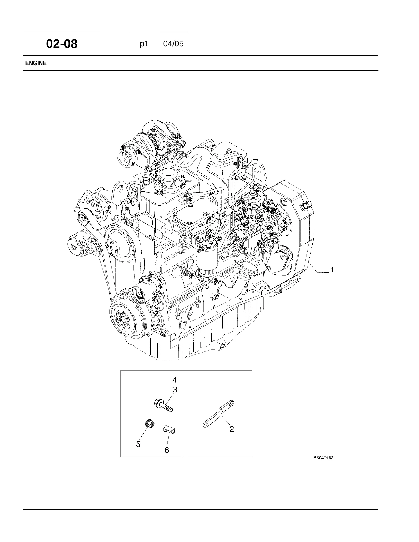
The engine portion begins with radiator mounting, deaeration, radiator assemblies, air-cleaner and intake components, turbocharged and non-turbocharged exhaust arrangements, engine mounting and block-heater equipment. Internal engine coverage then breaks down the cylinder block, oil pan, covers, breather, cylinder head, valve mechanism, intake and exhaust manifolds, crankshaft, pistons and connecting rods, flywheel, crankshaft pulley, dynamic balancer, camshaft and turbocharger. Lubrication and cooling components include the engine oil system, oil pump, filters, oil piping, oil cooler, water pump, thermostat, fan drive and related controls. Exploded drawings help identify individual fasteners, seals, bearings, gaskets, housings and subassemblies.
Fuel Injection System
Fuel-system coverage includes the reservoir and fuel lines, hand and foot throttle controls, injection pump, injection nozzles, injection tubes, fuel filter and transfer pump. The fuel-tank figures distinguish the 31 gal tank and optional 40 gal tank and show associated sender units, venting, hoses, covers and check-valve arrangements. Injection-system drawings provide component references for turbocharged and non-turbocharged engine variants where different pumps, injectors or connections are used.
Electrical
The electrical chapter identifies the starter, alternator, starter and alternator mounting, engine and chassis harnesses, battery cables, dual-battery cold-start equipment and grid-heater components. Front- and side-console harnesses are covered with fuses, relays, diodes, switches and connectors. Further sections include instrument panels, the instrument cluster, canopy and cab lighting, work lamps, horn, backup alarm, rotating beacon, radio antenna and speaker hardware, plus electrical components for auxiliary backhoe hydraulics and pilot controls. Internal starter and alternator exploded views are particularly useful when identifying serviceable subcomponents rather than replacing an entire unit.
Steering and Front Axle
The steering sections cover steering-wheel and column components, hydraulic steering hoses and control valve equipment, steering-column variations and the two-wheel-drive front axle. The 2WD axle is separated into mounting, housing, swivel housing, steering cylinder, hub and bearing assemblies. Wheel and tire pages identify the rim arrangements used with the cataloged front-tire sizes.
Front Drive Axle, Transmission and Rear Drive Axle
Four-wheel-drive coverage includes front axle mounting, housing and swivel components, steering cylinder, axle shafts, planetary assemblies, differential, ring-and-pinion components and the front drive shaft. The transmission portion covers cooling lines and cooler arrangements, mounting, oil filter, separate 2WD and 4WD housings, charge pump, shifter mechanism, idler and primary shafts, input shaft, secondary shaft, 4WD output shaft, transmission control valves and the 4WD solenoid valve. The catalog identifies both 2WD and 4WD replacement transmission assemblies and follows their internal components through the associated figures.
Rear driveline coverage includes rear wheels, rear-axle mounting, differential-lock hydraulics, axle housing, differential assemblies, ring and pinion, planetary components and rear drive shaft. Separate figures distinguish the 384952A1 rear axle with two-spider differential from the 87422891 axle with four-spider differential, including the related conversion/service-kit references where shown.
Brake
Brake-related material covers rear-axle differential brakes, parking brake components, brake pedals, brake-master-cylinder hydraulics, master-cylinder assembly parts and parking-brake controls. These drawings are useful for tracing the hardware and hydraulic components associated with the braking and parking systems rather than treating the brake assembly as a single item.
Hydraulics
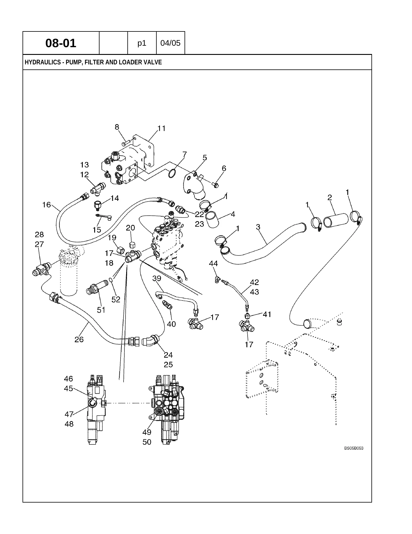
Hydraulic coverage is one of the largest parts of this Case 580M illustrated parts catalog. It starts with the pump, filter and loader valve, followed by loader-valve-to-backhoe-valve plumbing, cooler and return lines and filtration. Individual cylinder sections cover loader lift, loader bucket, loader clam, backhoe stabilizer, swing, boom, dipper, bucket and extendable dipper. Separate entries distinguish machines with and without pilot controls where the component arrangement changes.
The control side includes six-, seven- and eight-spool valve combinations, pilot-control valves and joysticks, auxiliary hydraulics, ride control, loader tool quick-coupler hydraulics, equipment hydraulic pump, loader control valves, backhoe control-valve assemblies, individual valve sections and pressure-reducing valves. Later figures break the cylinders themselves into service parts. For technicians working through a leak, damaged cylinder assembly, valve replacement or control-system parts order, these exploded views make it easier to determine exactly which assembly and configuration is involved.
Loader and Backhoe
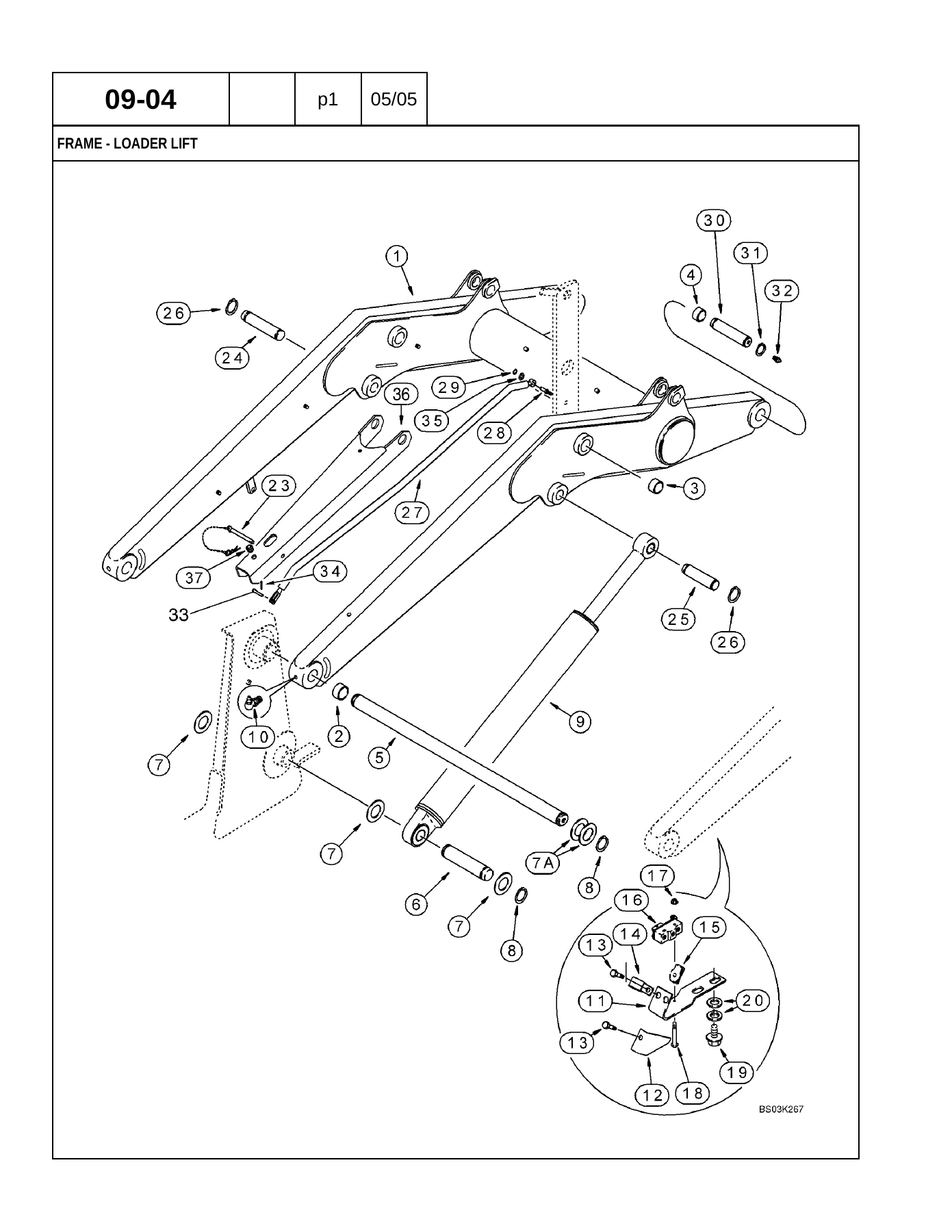
The loader section covers lift and bucket controls, loader-clam controls, self-leveling components, lift frame, linkage, multiple loader bucket arrangements, loader-valve guard and tool quick coupler. Backhoe coverage includes control towers for both pilot and non-pilot versions, foot-swing and hand-swing controls, excavator-pattern controls, auxiliary-hydraulic controls, stabilizers, swing tower, boom, boom latch, dipper, extendable dipper and numerous backhoe bucket sizes and configurations.
Because the catalog combines structural exploded views with associated hydraulic and control sections, it can be used to trace a component from the operator control through the valve or cylinder to the working attachment. This is particularly valuable on machines equipped with optional extendable dipper, auxiliary hydraulics or pilot controls, where the correct parts arrangement differs from a basic configuration.
Chassis, Cab and ROPS Equipment
Body and operator-station coverage includes counterweight, chassis and pod mounting, oil tank and battery/tool box, radiator wrapper, hood and grille panels, floor plates, fender components, mud guards and several seat and suspension arrangements. Cab sections identify glass, mirrors, doors, windows, washer and wiper equipment, headliner, air filter, blower housing, ventilation ducts, heater components and air-conditioning lines, evaporator, condenser, receiver-drier and compressor. ROPS canopy parts include frame, covers, mirrors, visor, glass, wiper and windshield-washer components. The catalog closes out this area with mirrors, slow-moving-vehicle emblem and decal groups, including separate decal listings for English, Latin American Spanish and Canadian French applications.
A Practical Reference for Parts Work on the Case 580M
For a machine with this many option-dependent assemblies, ordering by appearance alone can be expensive. The Case 580M Loader Backhoe Parts Catalog – Illustrated Parts Manual PDF gives you the exploded diagrams and corresponding part-number lists needed to identify assemblies systematically. It supports parts research across the engine, driveline, transmission, steering, brakes, hydraulics, loader, backhoe, electrical system and operator station, while the configuration notes help separate components used on turbo versus non-turbo machines, 2WD versus 4WD versions, pilot-control arrangements and other cataloged options.
Use it when dismantling an assembly and you need to see how components relate, when checking whether a seal, bearing, hose, valve, bracket or fastener is listed separately, when comparing replacement and superseded numbers, or when preparing a parts order before repair work begins. Having the complete illustrated Case 580M parts manual on hand reduces guesswork and gives you a much clearer parts reference than working from isolated numbers or photographs.
Instant PDF delivery means there is no book to ship and no waiting for postal delivery. Open the catalog on a computer, tablet or phone and print the pages you need for the workshop, parts counter or field job. With 2,420 pages of Case 580M component identification and exploded parts drawings available in one file, this is a substantial working reference for owners, mechanics, parts departments and equipment repair businesses maintaining the 580M Loader Backhoe.
IMAGES PREVIEW
Reviews
There are no reviews yet.