
Case 580N 580SN-WT 580SN 590SN Loader Backhoe Service Manual 2010 – Sections E F H J
Original price was: $39.95.$24.95Current price is: $24.95.
Complete PDF service manual for Case 580N, 580SN-WT, 580SN and 590SN Loader Backhoe covering Frame & Cab, Frame Positioning, Hitch & Working Tool, and Excavating & Landscaping. Part number 84393974, October 2010.
Description
Case 580N 580SN-WT 580SN 590SN Loader Backhoe Service Manual – Sections E, F, H, J
This Case 580N 580SN-WT 580SN 590SN Loader Backhoe Service Manual is the exact repair reference for the E, F, H, and J service sections of the machine. Published under part number 84393974 in October 2010, it delivers the disassembly, inspection, assembly, adjustment, and removal/installation procedures required to service the cab, operator controls, stabilizers, backhoe boom, dipper, attachments, and digging tools on the 580N, 580SN WT, 580SN, and 590SN loader backhoes.
File Details
- Manual type: Service Manual (Sections E, F, H, J)
- Brand: Case
- Models covered: 580N, 580SN WT, 580SN, 590SN Loader Backhoe
- Language: English
- Part number: 84393974
- Publication date: October 2010
- Page count: 455 pages
- File format: PDF
Chapters Covered in This Case 580N 580SN 580SN-WT 590SN Service Manual
- FRAME AND CAB (E)
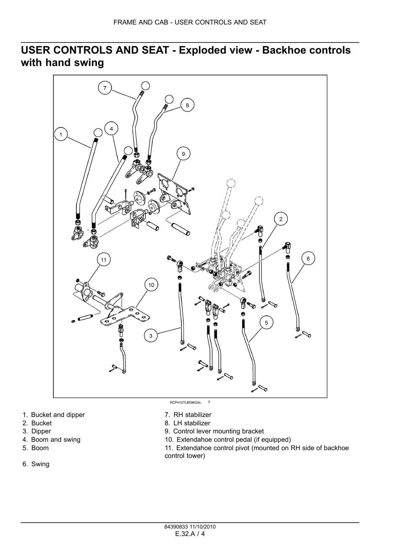
- User Controls and Seat (32.A) – backhoe controls with foot swing, backhoe controls with hand swing, adjustment of backhoe control levers, air suspension seat disassembly / inspection / assembly, instrument panel visual inspection, instrument cluster checks, removal, disassembly, assembly, install
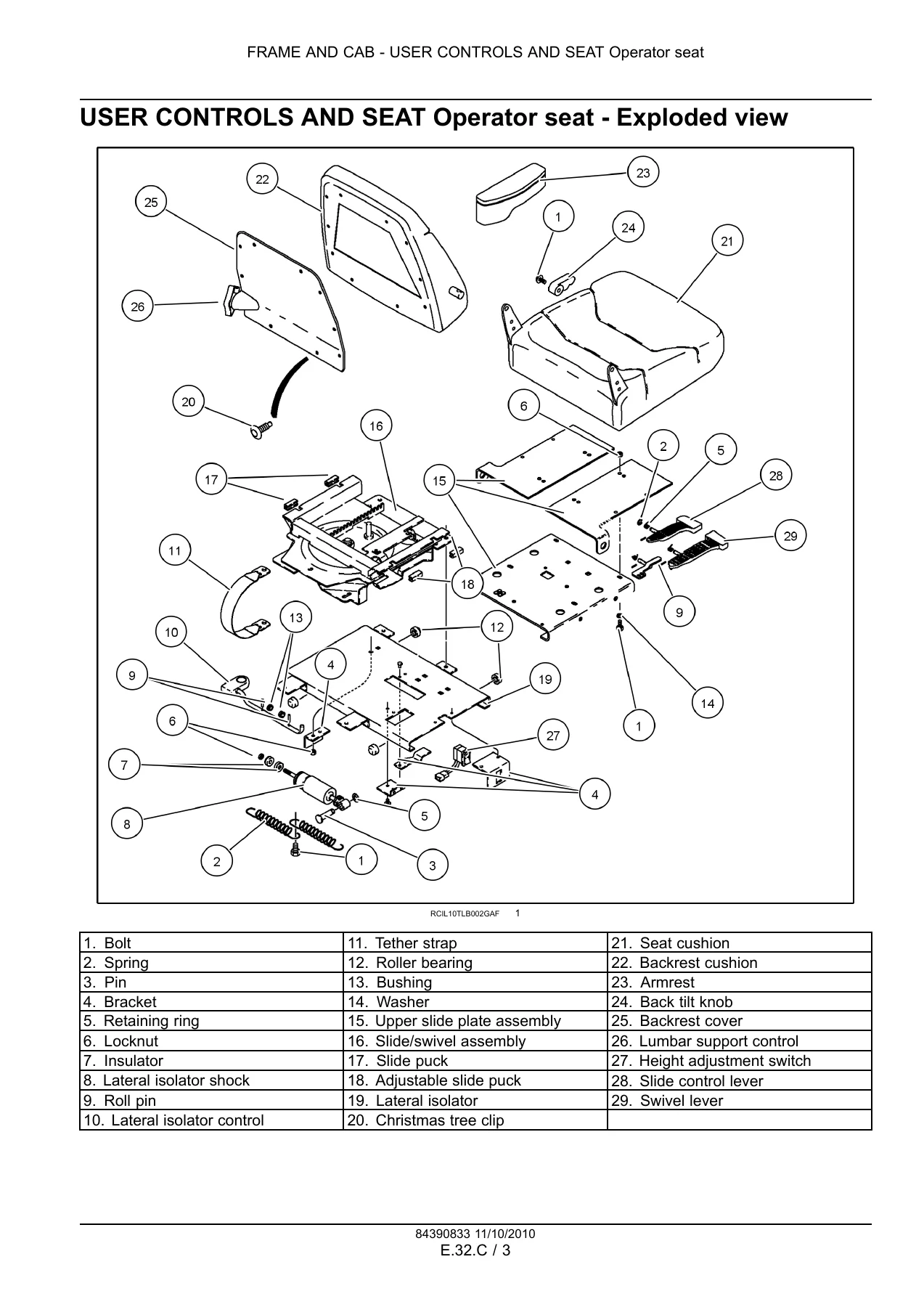
- Operator Seat (32.C) – pivot safety switch replacement, pedestal seat disassembly / inspection / assembly, mechanical suspension seat disassembly / inspection / assembly, air suspension seat disassembly / inspection / assembly, seat belt installation
- User Platform (34.A) – ROPS removal and installation, door, window and windscreen exploded views, rear window top / middle / bottom removal and installation
- Environment Control – Air-Conditioning System (40.C) – general specifications, special tools, safety procedures, operation overview, compressor clutch exploded view, expansion valve exploded view, system evacuation and recharging, pressure and temperature testing, current check, compressor belt adjustment, oil level check, clutch disassembly / assembly, condenser check, evaporator core removal / install, expansion valve testing
- FRAME POSITIONING (F)
- Stabilising Working Stabilising (20.D) – stabilizer cylinder torque values, special tools, cylinder exploded view, sectional view, pilot controlled hydraulic stabilizer cylinder hydraulic line exploded view, mechanical controlled hydraulic stabilizer exploded view, stabilizer exploded views for 580N / 580SN / 580SN-WT and 590SN
- HITCH AND WORKING TOOL (H)
- Boom Lift (20.B) – boom cylinder torque and special tools, exploded view, sectional view, boom arm exploded view, relief valve pressure test and replacement, boom cylinder remove / disassemble / overhaul / assemble / install, boom arm remove / install
- Boom Swing (20.D) – swing cylinder torque and special tools, swing tower cylinder exploded view and sectional view, swing tower exploded view and sectional view, mechanical linkage control overviews, pilot control overview, relief valve pressure test and replacement, swing cylinder remove / disassemble / overhaul / assemble / install, swing tower remove / install
- Dipper Lift (25.B) – dipper cylinder torque and special tools, exploded view, sectional view, dipper and bucket exploded views for each model, relief valve pressure test and replacement, dipper cylinder remove / disassemble / overhaul / assemble / install, dipper arm remove / install
- Dipper Extension (25.F) – extendable dipper cylinder torque and special tools, extendable dipper installation exploded views for each model, cylinder exploded view and sectional view, dipper extension remove / install, wear plate replacement procedures
- Arm Tool Attachment Tilt (30.C) – arm tool attachment cylinder torque and special tools, cylinder exploded view, relief valve pressure test and replacement, cylinder remove / install
- EXCAVATING AND LANDSCAPING (J)
- Digging Non-Articulated Digging Tools (20.B) – weld specifications for standard bucket, return-to-dig adjustment, antirollback adjustment, loader lift bucket control exploded views, loader frame and bucket frame exploded views, lift cylinder hydraulic installation, bucket cylinder hydraulic installation, clam cylinder circuit and hydraulic installation, antirollback linkage, boom latch drawings, backhoe auxiliary control, bucket teeth locations, clam control valve / clam lock valve sectional view, cutting edge replacement, tooth shank and tooth point replacement, loader frame removal and installation
- Carrying Articulated Tools (50.C) – control valve special torques, mechanical linkage backhoe control valve exploded views, circuit relief valve exploded view, typical cylinder exploded views, quick coupler cylinder exploded view, control valve check / remove / install, quick coupler cylinder disassemble / inspect / assemble
This Case 580N 580SN 590SN service manual is the section-specific reference a technician reaches for when the job involves the operator station, the ROPS cab and its glass, the air-conditioning system, the stabilizer legs, or the entire backhoe end of the machine. Every procedure is tied to a machine configuration – whether the backhoe uses mechanical linkage controls or pilot controls, whether the stabilizer is mechanically or pilot controlled, and whether the dipper is a standard or Extendahoe unit. Torque values are not generalized; they are broken out per model, so the 580N and 580SN piston bolt torque differs from the 580SN WT and 590SN figure, and the air suspension seat section alone runs from removal through inspection to assembly with the isolator control, roller bearings, air compressor, air spring, and pedestal all individually addressed.
The Section E Frame and Cab content is unusually deep for an operator-area manual. It walks through instrument cluster self-test behaviour, warning lamp diagnostics for low engine oil pressure, alternator, hydraulic oil filter restriction, air filter restriction, parking brake, driving lamps, low fuel level, air conditioning system pressure, and grid heater. It also documents the software version retrieval and configuration mode procedures. The air-conditioning section covers HFC-134a system evacuation and recharging with a pressure-temperature chart, recovery procedures, oil level checks, clutch disassembly and assembly with shim and gap measurements, and expansion valve testing using an ice-water method.
The Section F Frame Positioning content concentrates on the stabilizer cylinders, with torque values that distinguish between the 580N / 580SN group and the 580SN WT / 590SN group, plus exploded and sectional views for both pilot controlled and mechanical controlled hydraulic stabilizer arrangements.
The Section H Hitch and Working Tool content covers the entire backhoe attachment chain: boom lift, boom swing, dipper lift, dipper extension, and arm tool attachment tilt. Each cylinder family has its own torque table, special tool references, exploded view, sectional view, relief valve test and replacement, and a complete remove – disassemble – overhaul – assemble – install sequence. The swing tower itself is documented with exploded and sectional views, plus removal and installation procedures that include the shim and washer positioning critical to smooth swing tower operation.
IMAGES PREVIEW
The Section J Excavating and Landscaping content handles the digging tools and the articulated tool-carrying systems. This includes bucket weld specifications, cutting edge replacement for standard, clam, universal, heavy duty, and high capacity buckets, tooth shank and tooth point replacement, bucket teeth location drawings, loader frame removal and installation, antirollback adjustment, return-to-dig adjustment, and the clam control valve / clam lock valve sectional view. The 50.C control valve section provides special torque values for relief valves, check valves, anti-void assemblies, end cap bolts, and centering spring hardware.
Why This Case 580N 580SN 580SN-WT 590SN Service Manual Matters
Backhoe loaders are worked hard, and the components in Sections E, F, H, and J take the brunt of that work. Cab mounts, seat suspensions, stabilizer cylinders, swing towers, boom and dipper cylinders, and digging tools all wear, leak, crack, or need adjustment. Without the correct torque values, shim arrangements, seal orientations, and diagnostic flow, a repair can turn into a repeat failure. The seal orientation notes alone – buffer seal lip direction, wiper lip direction, backup ring flat-side orientation – are the difference between a cylinder that seals and one that weeps within a week.
This manual also carries the model-specific detail that generic backhoe references miss. The swing tower removal procedure warns that shim and washer location, orientation, and size are critical to smooth operation and must be recorded before removal. The air suspension seat inspection calls out molysidful grease for the roller bearings and contact points. The instrument cluster section explains exactly which lamps illuminate for a bulb self-test and how to read active faults. That level of specificity is what makes this Case 580N 580SN 580SN-WT 590SN loader backhoe service manual worth keeping on hand.
Instant PDF Delivery
This Case 580N 580SN 590SN service manual is delivered as an instant PDF download after payment. No shipping, no waiting, no physical binder to lose. Open it on a laptop, tablet, or phone in the shop, print the pages you need for the job, and keep the rest of the file clean. With 455 pages organized by section and subsystem, you can jump straight to the stabilizer cylinder, the air suspension seat, the swing tower, or the bucket cutting edge procedure without paging through unrelated content. Whether you are diagnosing an instrument cluster fault, resealing a boom cylinder, replacing a tooth shank, or pulling the cab for ROPS service, this manual gives you the procedures, torque values, and inspection criteria to do the job correctly the first time.
Reviews
There are no reviews yet.