
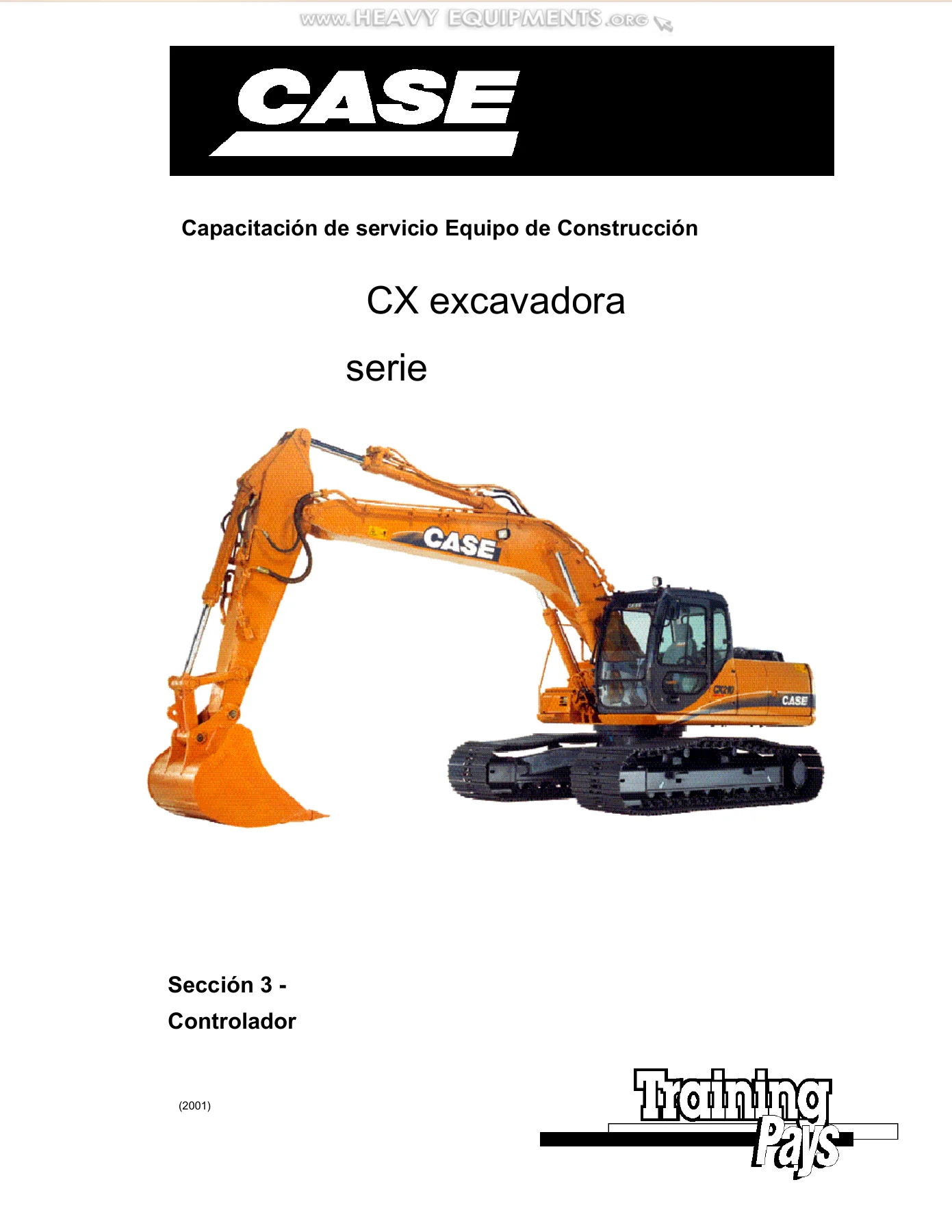
Case CX130 CX160 CX210 CX240 Excavator Service Training Manual 2001 English Spanish – PDF Download
Original price was: $59.95.$39.95Current price is: $39.95.
Complete service training manual for Case CX130, CX160, CX210, and CX240 excavators. Covers hydraulic systems, electrical controls, controller diagnostics, pressure specifications, and engine fuel electronics. 273 pages, English and Spanish, instant PDF download.
Description
Case CX Excavator Series Service Training Manual – CX130, CX160, CX210, CX240
This Case CX Excavator Series Service Training Manual is the comprehensive technical training resource used to educate service technicians on the CX130, CX160, CX210, and CX240 excavators. Produced by Case Corporation in 2001, this 273-page PDF manual covers the complete machine systems in both English and Spanish, making it an essential reference for anyone maintaining, diagnosing, or repairing these excavators.
Whether you are a professional heavy equipment technician, a fleet maintenance manager, or an owner-operator performing your own service work, this Case CX130 CX160 CX210 CX240 service training manual gives you the same in-depth system knowledge that factory-trained technicians receive. Every major system is broken down into clear explanations of how it works, why it works that way, and what to check when it doesn’t.
File Details
- Manual Type: Service Training Manual
- Brand: Case
- Models Covered: CX130, CX160, CX210, CX240
- Language: English, Spanish
- Page Count: 273 pages
- File Format: PDF
- Publication Year: 2001
- Document Number: 5087
Chapters Covered
- Section 1 – General Introduction
- Section 2 – Component Location (Hydraulic / Electrical)
- Section 3 – Controller
- Section 4 – Electrical: How It Works
- Section 5 – Hydraulic: CX130 / CX160 How It Works
- Section 6 – Hydraulic: CX210 / CX240 How It Works
- Section 7 – Pressure Data Sheets
- Section 8 – Engine Fuel Electronics System
- Section 9 – Miscellaneous
- Section 10 – Schematics
Section 1 – General Introduction
This opening section provides the foundational specifications for all four models, including engine data, hydraulic tank capacities, filter specifications, pump flow rates, and control configurations. You’ll find the CX series model identification table, which maps manufacturing model numbers to Case model numbers (SHO120 to CX130, SHO150 to CX160, SHO200 to CX210, SHO220 to CX240), as well as the language code table for controller programming. The section also introduces the variable displacement pump system, the open-center hydraulic design, and the cushion control system that smooths boom and arm operation.
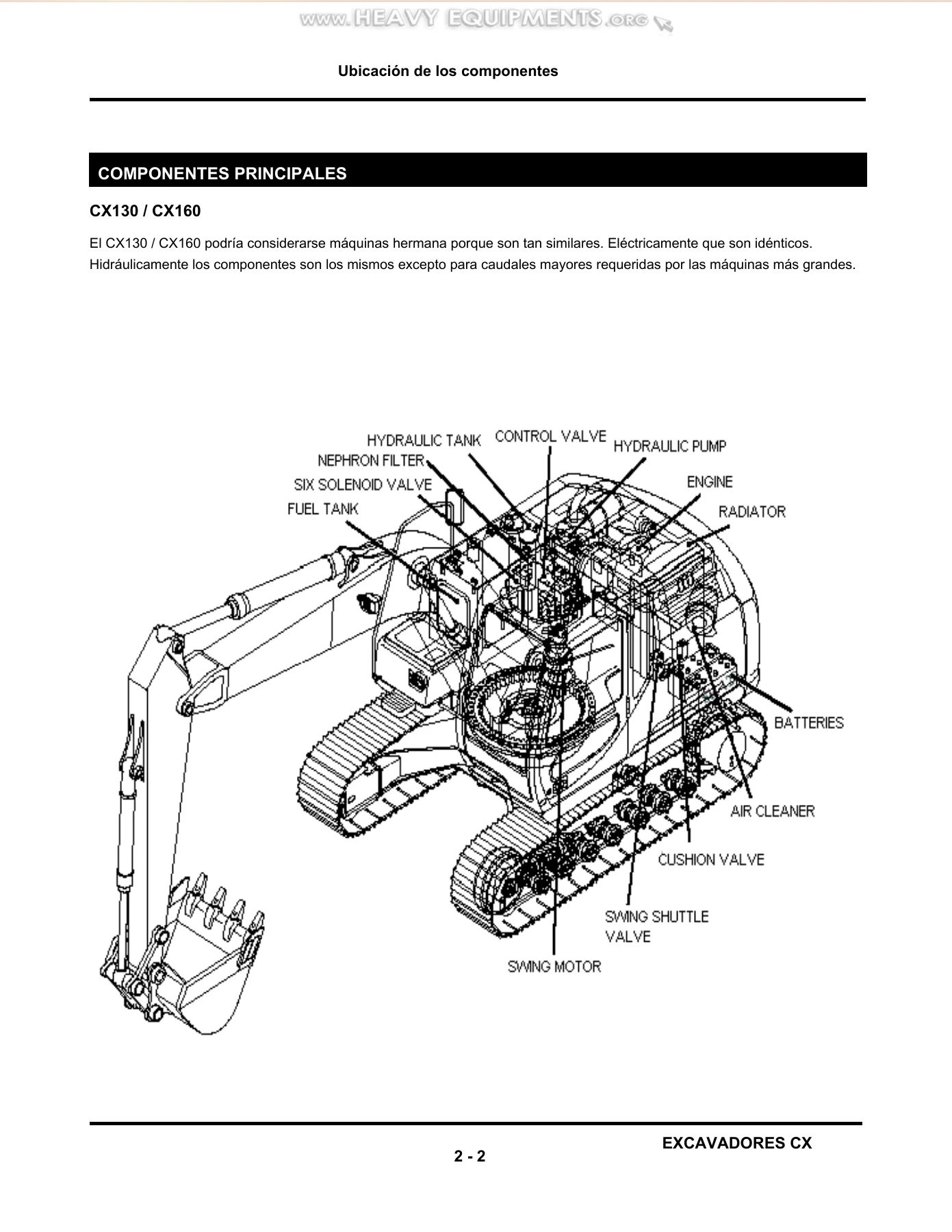
Section 2 – Component Location
This section provides detailed component location diagrams for both the CX130/CX160 and CX210/CX240 groups, showing the physical placement of major hydraulic and electrical components. You’ll find labeled illustrations of the hydraulic tank, control valve, hydraulic pump, engine, radiator, batteries, air cleaner, swing motor, cushion valve, and swing shuttle valve. Electrical component locations are covered both inside and outside the cab, with numbered callouts for solenoid valves, pressure switches, sensors, transducers, fuses, relays, and the electronic controller. A comprehensive control valve port description table explains the function of every port on the main control valve.
Section 3 – Controller
The controller section is the diagnostic heart of this manual. It covers the calibration procedure for the electronic controller, including how to set the machine model, territory, and language using the monitor panel switches. You’ll learn how to navigate the diagnostic modes: CHK1 through CHK6 for current conditions, DIAG1 through DIAG6 for fault codes and past conditions, HR1 through HR12 for machine history and operating hours distribution, and RST1 for resetting optional settings. The section explains how to read pump pressures, engine RPM, proportional solenoid current, switch inputs, and transistor outputs. It also covers fault code listings for both the engine and machine systems, including specific codes for the CX210/CX240 engine ECM communication.
Section 4 – Electrical: How It Works
This section explains the electrical control systems in plain language. It covers the throttle control system for both the CX130/CX160 (stepper motor with 1023 pulses over 52 degrees of rotation) and the CX210/CX240 (engine controller-managed). You’ll find detailed explanations of auto idle control, one-touch idle, RPM control for H, S, L, and Auto work modes, automatic engine warm-up, and breaker revolution control. The section also covers electrical controls over hydraulic functions: pump control, power boost, 2-speed travel, cushion on/off, swing brake and swing lock, free swing, and the pilot lock lever. Each system is explained with circuit diagrams showing the controller, solenoids, switches, and sensors involved.
Section 5 – Hydraulic: CX130 / CX160 How It Works
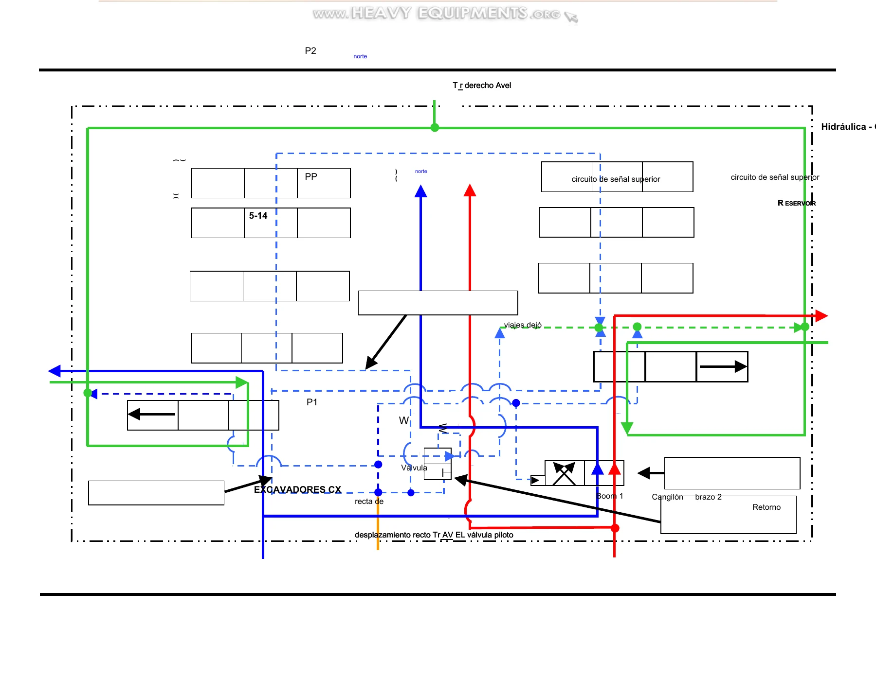
This section is dedicated to the hydraulic systems specific to the CX130 and CX160. It covers low-speed and high-speed travel, including how the motor swashplate angle changes and how the controller manages the 2-speed solenoid. Straight-line travel is explained, showing how one pump is dedicated to the travel motors when combined operations are performed. Swing operation with brake control, swing lock, and swing priority are covered in detail. Attachment circuits for boom raise, boom lower, arm open, arm close, and the cushion function are explained with circuit diagrams. The section also covers one-touch power boost, the main relief valve with its two pressure settings, negative flow control (pump de-stroke), and free swing operation. Hydraulic schematic diagrams show the circuits for each function.
Section 6 – Hydraulic: CX210 / CX240 How It Works
Parallel to Section 5, this section covers the hydraulic systems unique to the CX210 and CX240. The larger machines use a Kawasaki pump instead of the Uchida pump found on the smaller models, and the hydraulic control logic has model-specific differences. Topics include low and high-speed travel, straight-line travel, swing operation with brake control, swing lock, swing priority, boom raise, boom lower, arm open, arm close, cushion operation, automatic power boost, main relief valve operation, pump de-stroke, and free swing. The section includes hydraulic circuit diagrams for each function and explains how the controller monitors pump pressure and engine load to activate automatic power boost.
Section 7 – Pressure Data Sheets
This section provides the pressure specifications for all four models. Each model has its own pressure data sheet listing main relief pressure (standard and power boost settings), boom circuit relief pressures (up and down), bucket circuit relief, arm circuit relief, swing motor crossover relief, travel crossover relief, and pilot circuit pressure. The data sheets include the conditions for measurement, such as work mode, hydraulic oil temperature, and engine speed. These specifications are essential for verifying system performance and troubleshooting pressure-related issues.
Section 8 – Engine Fuel Electronics System
This section covers the electronically controlled fuel system used on the CX210 and CX240 engines. It explains the Bosch VP44 injection pump, the engine control module (ECM), the fuel pump control module (FPCM), and the various sensors including engine speed sensor, engine position sensor, intake manifold temperature sensor, boost pressure sensor, coolant temperature sensor, and oil pressure sensor. The section covers the fuel system flow, air heater operation, fuel connectors, and troubleshooting procedures. A complete fault code listing includes descriptions, associated hardware, reason for the fault, and the effect on engine operation.
Why This Manual Matters
The Case CX excavator service training manual is not a generic repair guide. It is the actual training material used to teach technicians how the CX series machines work at a system level. When you understand how the hydraulic and electrical systems are designed to operate, you can diagnose problems faster and more accurately. Instead of guessing at which component might be faulty, you can trace the circuit, verify pressures against the specifications, and use the controller’s diagnostic modes to pinpoint the issue.
For the CX130 and CX160, the manual covers the Uchida pump and the specific hydraulic control logic for those models. For the CX210 and CX240, it covers the Kawasaki pump and the electronically controlled engine. Having both hydraulic sections in one document means you can work on any machine in the CX series without needing multiple manuals.
The diagnostic procedures in Section 3 are particularly valuable. The controller’s built-in self-test functions allow you to check switch inputs, transistor outputs, sensor readings, and fault codes without external diagnostic equipment. The manual explains how to enter each diagnostic mode, what the values mean, and how to clear codes after repairs.
Who This Manual Is For
This Case CX130 CX160 CX210 CX240 service training manual is written for heavy equipment technicians, field service engineers, fleet maintenance personnel, and owner-operators who need to understand the CX series at a component and system level. It is also valuable for technical trainers and students in heavy equipment programs who want to learn how modern excavator hydraulics and electronics are integrated.
The bilingual format (English and Spanish) makes it particularly useful for service operations in bilingual regions or for technicians who are more comfortable working in one language for certain systems.
Get Instant Access
IMAGES PREVIEW
This Case CX Excavator Service Training Manual is delivered as an instant PDF download. There is no waiting for shipping, no physical media to handle, and no risk of a damaged book arriving. You can access the manual immediately after purchase on any device that reads PDFs — laptop, tablet, or smartphone. Print the pages you need for the shop, or keep the entire 273-page manual on your device for quick reference in the field.
Whether you are performing a scheduled service, diagnosing a hydraulic fault, or trying to understand why the controller is showing a particular code, this manual gives you the information you need to get the job done correctly. Get your copy today and have the complete CX series training resource at your fingertips.
Reviews
There are no reviews yet.