
CASE CX15B CX18B Mini Excavator Service Manual 84533370A PDF
Original price was: $44.95.$26.95Current price is: $26.95.
Complete service and repair reference for CASE CX15B and CX18B hydraulic mini excavators. Covers technical specifications, working attachments, hydraulic and electrical systems, component removal and installation, travel system service, troubleshooting, engine procedures, inspection standards, tightening data and detailed circuit diagrams.
Description
CASE CX15B CX18B Mini Excavator Service Manual 84533370A PDF
The CASE CX15B CX18B Mini Excavator Service Manual 84533370A PDF is a detailed technical service reference for the CX15B and CX18B hydraulic mini excavators. It provides the procedures, specifications, service standards and system information needed to carry out maintenance and repair work on these machines. Coverage extends from basic preparation for disassembly through hydraulic and electrical diagnosis, working attachment repair, undercarriage service, major component work and engine servicing.
This is a substantial manual for technicians working beyond routine operator maintenance. It explains how assemblies are constructed and operated, provides removal, installation, disassembly and reassembly procedures, and includes inspection values that can be used to judge whether components require adjustment, repair or replacement. Separate hydraulic information is provided for the CX15B and CX18B where their systems differ.
File Details
- Manual type: Service Manual
- Brand: CASE
- Models: CX15B, CX18B
- Machine type: Hydraulic Mini Excavators
- Language: English
- Pages: 607
- File format: PDF
- Print number: 84533370A
Technical Service Information for CX15B and CX18B
The CASE CX15B CX18B service manual begins with service precautions and preparation practices for safe disassembly and assembly. It addresses hydraulic attachments, electrical equipment, hydraulic parts, welding repairs and environmental precautions, then moves into the machine’s technical data. Dimension drawings cover cab and canopy configurations, while specifications describe machine performance, crawler and bucket arrangements, engine data and lubricant, fuel and coolant requirements.
The engine fitted to the machines is identified in the manual as the L3E-31KBSA. The technical specification section gives its construction and operating data, including cylinder arrangement, bore and stroke, displacement, rated output, maximum torque, engine speeds, fuel injection pressure, lubrication information, cooling data and electrical starting equipment. The manual also includes an engine performance curve and fluid information for the machine’s hydraulic system, engine, fuel system, cooling system and travel motors.
Hydraulic System and Circuit Coverage
Hydraulic information is a major part of this CASE CX15B CX18B Mini Excavator Service Manual 84533370A PDF. The CX15B receives its own hydraulic section with diagrams for one-speed and two-speed configurations, plus the optional nibbler and breaker system. The manual then explains individual circuit operations such as travel, slewing, bucket, boom, arm, dozer, swing and combined operations.
The CX18B hydraulic section is treated separately and includes its own hydraulic diagram and circuit descriptions. It covers two-speed travel, slewing, bucket, boom and arm functions as well as swing, dozer and track-width adjustment operation, combined travel functions and nibbler/breaker operation. Color-coded operating circuit illustrations make it possible to follow pressure and return paths through pumps, control valves, motors, cylinders and related components.
Hydraulic service data also extends into the main-component chapter. Pump specifications and operation are described for both models, followed by attachment and travel control valves, model-specific main control valves, the slewing motor, one-speed and two-speed travel motors, rotary control valves and cylinders. Component drawings and internal views support disassembly, identification and understanding of how these assemblies work.
Inspection, Adjustment and Troubleshooting
The maintenance standards section is designed for checking machine condition against defined performance values. Separate standard-value tables are provided for the CX15B and CX18B. Procedures include measuring engine speed and hydraulic oil pressure, checking travel performance and deviation, evaluating movement caused by gravity, checking travel-motor oil drain rate, testing slewing time and overrun, measuring working-attachment cylinder speeds and drift, checking slewing-bearing play and measuring crawler tension.
These procedures are particularly useful when a machine has lost performance or when a technician needs measured data before deciding whether adjustment, repair or component replacement is necessary. Hydraulic pressure measurement instructions identify test conditions, measuring ports and adjustment procedures. The manual also supplies standard and repair-limit information for a range of performance checks.
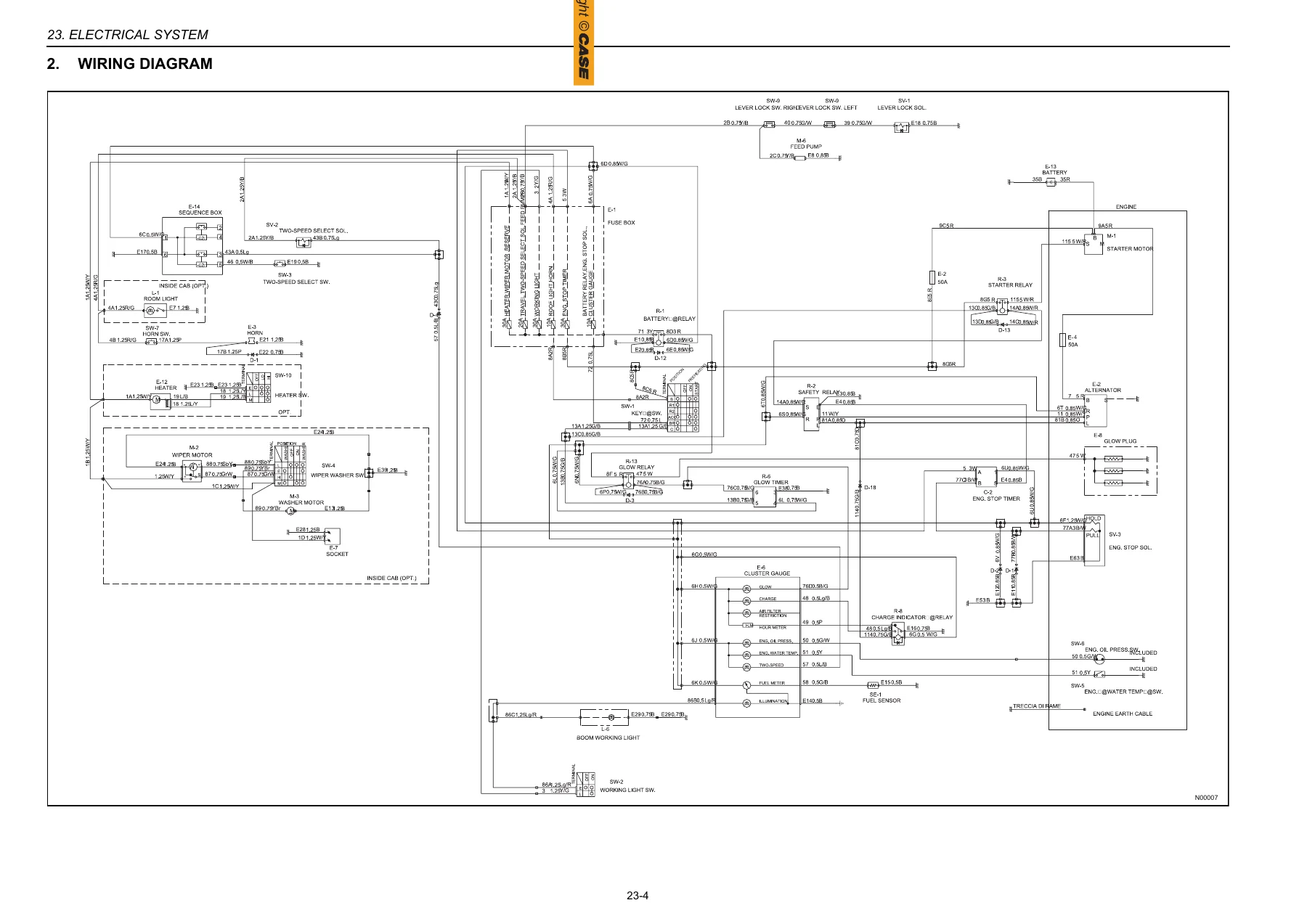
Dedicated troubleshooting chapters address both hydraulic and electrical problems. Hydraulic troubleshooting covers working-attachment symptoms, machine travel, swing and pump-related faults. Electrical troubleshooting works through faults such as starting problems and electrical equipment failures using checks of switches, relays, solenoids, sensors, wiring harnesses and other circuit components. A complete wiring diagram and electrical component layout information are included elsewhere in the manual to support this diagnostic work.
Removal, Installation and Mechanical Repair
Mechanical repair coverage goes well beyond system descriptions. The working attachment chapter includes dimensional and maintenance-standard information for the boom, arm, bucket, dozer and swing bracket, including pin and bushing tolerances and installation clearances. A later chapter provides actual removal and installation procedures for attachment pins, bucket, arm, boom, swing bracket, swing cylinder and dozer, followed by cylinder disassembly and assembly information.
The upper-frame section covers removal, installation and service work involving the canopy, cab, counterweight and other upper-frame equipment. It continues into service procedures for major hydraulic components, including control valves, slewing motor and rotary control valve assemblies. The travel-system chapter covers the rubber crawler and related undercarriage assemblies, including sliding plates, rollers, travel components and the CX18B track-width enlargement device. Disassembly and assembly information is also provided for the one-speed CX15B travel motor and the two-speed travel motor used with the CX15B and CX18B.
Chapters Covered
- 1 – Description
- General Precautions for Installation
- Preparation Before Disassembly
- Safety During Disassembly and Assembly
- Hydraulic Attachment, Electrical Equipment and Hydraulic Parts
- Welding Repair and Environmental Precautions
- Measuring Unit Conversion Tables
- 2 – Technical Specifications
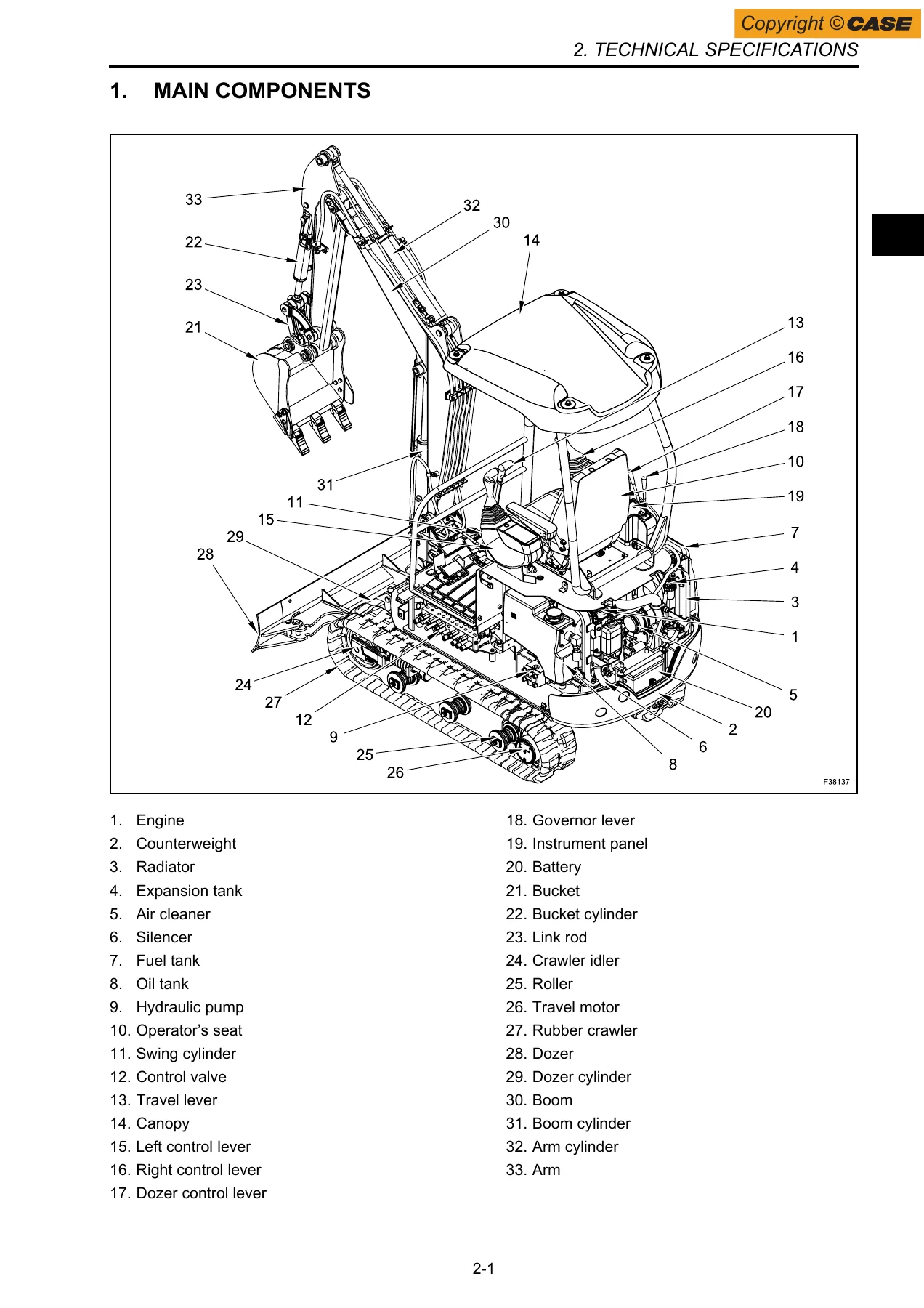
- Main Components
- Machine Dimensions – Cab and Canopy
- Specifications and Performance
- Crawler Type and Bucket Type
- Engine Specifications and Performance Curve
- Lubricant, Fuel and Coolant Specifications
- 3 – Working Attachment
- Boom Dimensions and Maintenance Standards
- Arm Dimensions and Maintenance Standards
- Bucket Types and Dimensions
- Fixed and Extendable Dozer
- Swing Bracket Dimensions, Assembly and Disassembly
- 11 – Tools
- Torque Specifications for Screws and Nuts
- Screw Dimensions
- Torque Specifications for Fittings, Hoses and Hose Sleeves
- Special Wrenches for Tubes and Sealants
- 13 – Maintenance Standards and Inspection Procedures
- CX15B and CX18B Standard Value Tables
- Engine Speed and Hydraulic Oil Pressure Measurement
- Travel and Slewing Performance Measurement
- Working Attachment Performance Measurement
- Slewing Bearing Performance and Crawler Tension
- 22A – Hydraulic System – CX15B
- Hydraulic System Operation and Features
- One-Speed and Two-Speed Hydraulic Diagrams
- Optional Nibbler and Breaker Hydraulic Diagram
- Hydraulic Circuit Operation
- 22B – Hydraulic System – CX18B
- Hydraulic System Operation and Features
- CX18B Hydraulic Diagram
- Hydraulic Circuit Operation
- 23 – Electrical System
- How to Read Wiring Diagrams and Connections
- Wiring Diagram
- Electrical Equipment List
- Electrical Components and Wiring Harness Layout
- 24 – Main Components
- CX15B and CX18B Hydraulic Pumps
- Attachment and Travel Control Valves
- CX15B and CX18B Control Valves
- Slewing Motor
- One-Speed and Two-Speed Travel Motors
- CX15B and CX18B Rotary Control Valves
- Cylinders and Main Electrical System Components
- 32 – Working Attachment Removal and Installation
- Attachment Pin Installation
- Bucket, Arm, Boom, Swing Bracket and Dozer Removal and Installation
- Cylinder Disassembly and Assembly
- 33 – Upper Frame
- Removal and Installation of Upper-Frame Assemblies
- Service Procedures for Hydraulic Components
- 34 – Travel System
- Main Components
- Rubber Crawler and Undercarriage Removal and Installation
- CX18B Track Width Enlargement Device
- Travel Motor Disassembly and Assembly
- 42 – Troubleshooting – Hydraulic System
- General Troubleshooting Precautions
- Working Attachment
- Machine Travel
- Swing
- Pump
- 43 – Troubleshooting – Electrical System
- Electrical Troubleshooting
- Various Troubles
- Working Attachment and Machine Travel
IMAGES PREVIEW


- 51 – Engine
- General Information and Main Components
- Fuel, Lubrication, Cooling, Inlet and Exhaust Systems
- Engine Technical Specifications
- Disassembly and Assembly
- Inspection and Adjustment
- Break-In Operation
- Engine Troubleshooting
Taken together, these chapters provide a connected service reference rather than isolated specifications. A technician can identify the construction and operating principles of a system, check its performance against service standards, follow diagrams during diagnosis, remove and repair affected components, then use the specified inspection and adjustment information during reassembly.
Fastener, Hose and Service Data
The manual includes standard tightening specifications for coarse- and fine-thread fasteners, along with torque information for hydraulic fittings, hoses and hose sleeves. Tube wrench dimensions and listed sealing compounds are also provided. These references complement component-specific procedures throughout the manual and help support correct assembly when servicing hydraulic and mechanical systems.
Detailed illustrations are used throughout the CASE CX15B CX18B service manual. These include machine dimension drawings, attachment drawings, pin and bushing diagrams, hydraulic schematics, color-coded operating circuits, electrical wiring diagrams, component layouts, sectional views and exploded component illustrations. This visual material is especially useful when tracing circuits, identifying internal parts or confirming component orientation during disassembly and reassembly.
Service and Repair Your CX15B or CX18B with the Correct Reference
The CASE CX15B CX18B Mini Excavator Service Manual 84533370A PDF supports a wide range of workshop jobs, including hydraulic diagnosis and pressure testing, electrical fault tracing, engine service, attachment repair, crawler and travel-system work, control-valve and motor servicing, component removal and installation, inspection, adjustment and troubleshooting. Having the specified procedures, diagrams, tightening data, service standards and repair limits available helps technicians work from the machine’s documented technical information rather than relying on guesswork.
Delivered as an instant PDF download after purchase, there is no physical shipping or waiting for a printed book. The manual can be opened on compatible computers, tablets or phones and pages can be printed when a paper reference is more convenient at the machine or workbench.
Reviews
There are no reviews yet.