Case Hydraulic Excavator WX210 WX240 Tier 3 Service Manual 87677489A – PDF DOWNLOAD
Original price was: $90.95.$45.95Current price is: $45.95.
Case Hydraulic Excavator WX210 WX240 Tier 3 Service Manual
Part No: 87677489A
Description
Case Hydraulic Excavator WX210 WX240 Tier 3 Service Manual
FILE DETAILS:
Case Hydraulic Excavator WX210 WX240 Tier 3 Service Manual
Size : 52.7 MB
Format : PDF
Language : English
Number of Pages : 795 pages
Brand: Case
Type of machine: Hydraulic Exacvator
Type of document: Service Manual
Model: Case Hydraulic Excavator WX210 WX240 Tier 3
Part No: 87677489A
DESCRIPTION:
Case Hydraulic Excavator WX210 WX240 Tier 3 Service Manual
GENERAL INFORMATION:
- Carefully read this Manual before proceeding with maintenance, repairs, refuelling or other machine operations. Repairs have to be carried out only by authorized and instructed staff; specific precautions have to be taken when grinding, welding or when using mallets or heavy hammers. Not authorized persons are not allowed to repair or carry out maintenance on this machine. Do not carry out any work on the equipment without prior authorization.
- Ask your employer about the safety instructions in force and safety equipment. Nobody is allowed to seat on the operator’s place during machine maintenance unless he is a qualified operator helping with the maintenance work. If it is necessary to move the equipment to carry out repairs or maintenance, do not lift or lower the equipment from any other position than the operator’s seat. Never carry out any operation on the machine when the engine is running, except when specifically indicated.
- Stop the engine and ensure that all pressure is relieved from hydraulic circuits before removing caps, covers, valves, etc. All repair and maintenance operations should be carried out with the greatest care and attention. Service stairs and platforms used in a workshop or in the field should be built in compliance with the safety rules in force. Any functional disorders, especially those affecting the safety of the machine, should therefore be rectified immediately.
- Never leave the engine run in closed spaces without ventilation and not able to evacuate toxic exhaust gases. Keep the exhaust manifold and tube free from combustion materials. Do not refuel with the engine running, especially if hot, as this increases fire hazard in case of fuel spillage.
- Never attempt to check or adjust the fan belts when the engine is running. Never lubricate the machine with the engine running. Pay attention to rotary pieces and do not allow to anyone to approach to avoid becoming entangled. If hands, clothes or tools get caught in the fan blades or in the transmission belt, this can cause amputations, violent tears and generate condition of serious danger; for this reason avoid touching or to come close to all rotary or moving parts. A violent jet of the coolant from the radiator can cause damages and scalds.
- If you are to check the coolant level, you have to shut off the engine previously and to let cool down the radiator and its pipes. Slowly unscrew the cap to release the inside pressure. If necessary, remove the cap with hot engine, wear safety clothes and equipment, then loosen the cap slowly to relieve the pressure gradually. When checking the fuel, oil and coolant levels, use exclusively explosion proof classified lamps. If this kind of lamps are not used fires or explosions may occur.
- Splashes of fluids under pressure can penetrate the skin causing serious injuries. Avoid this hazard by relieving pressure before disconnecting hydraulic or other lines. Relieve the residual pressure by moving the hydraulic control levers several times. Tighten all connections before applying pressure. To protect the eyes wear a facial shield or safety goggles. Protect your hands and body from possible splashes of fluids under pressure. Swallowing hydraulic oil is a severe health hazard. When hydraulic oil has been swallowed, avoid vomiting, but consult a doctor or go to a hospital. If an accident occurs, see a doctor familiar with this type of injury immediately.
- Any fluid penetrating the skin must be removed within few hours to avoid serious infections. Flammable splashes may originate because of the heat near pipes with fluids under pressure, with the result of serious scalds for the persons hit. Do not weld or use torches near pipes containing fluids or other flammable materials. Pipes under pressure can accidentally be pierced when the heat expands beyond the area immediately heated. Arrange for fire resistant temporary shields to protect hoses or other components during welding. Have any visible leakage repaired immediately. Escaping oil pollutes the environment. Soak up any oil that has escaped with a proper binding agent.
- Sweep up binding agent and dispose of it separately from other waste. Never search for leakages with the fingers, but use a piece of cardboard and always wear goggles. Never repair damaged piping; always replace it. Replace hydraulic hoses immediately on detecting any damage or moist areas. Always store hydraulic oil in the original containers.
CASE HYDRAULIC EXCAVATOR WX210 WX240 TIER 3 SERVICE MANUAL 87677489A – PDF DOWNLOAD:
IMAGES PREVIEW OF THE MANUAL:
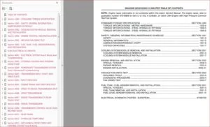
TABLE OF CONTENTS:
Case Hydraulic Excavator WX210 WX240 Tier 3 Service Manual
SECTION 01 – SAFETY PRECAUTIONS
1 GENERAL SAFETY INSTRUCTIONS 2
2 USE INSTRUCTION 11
SECTION 02 – CONTROLS AND INSTRUMENTS
1 SWITCHES AND PUSH-BUTTONS 1
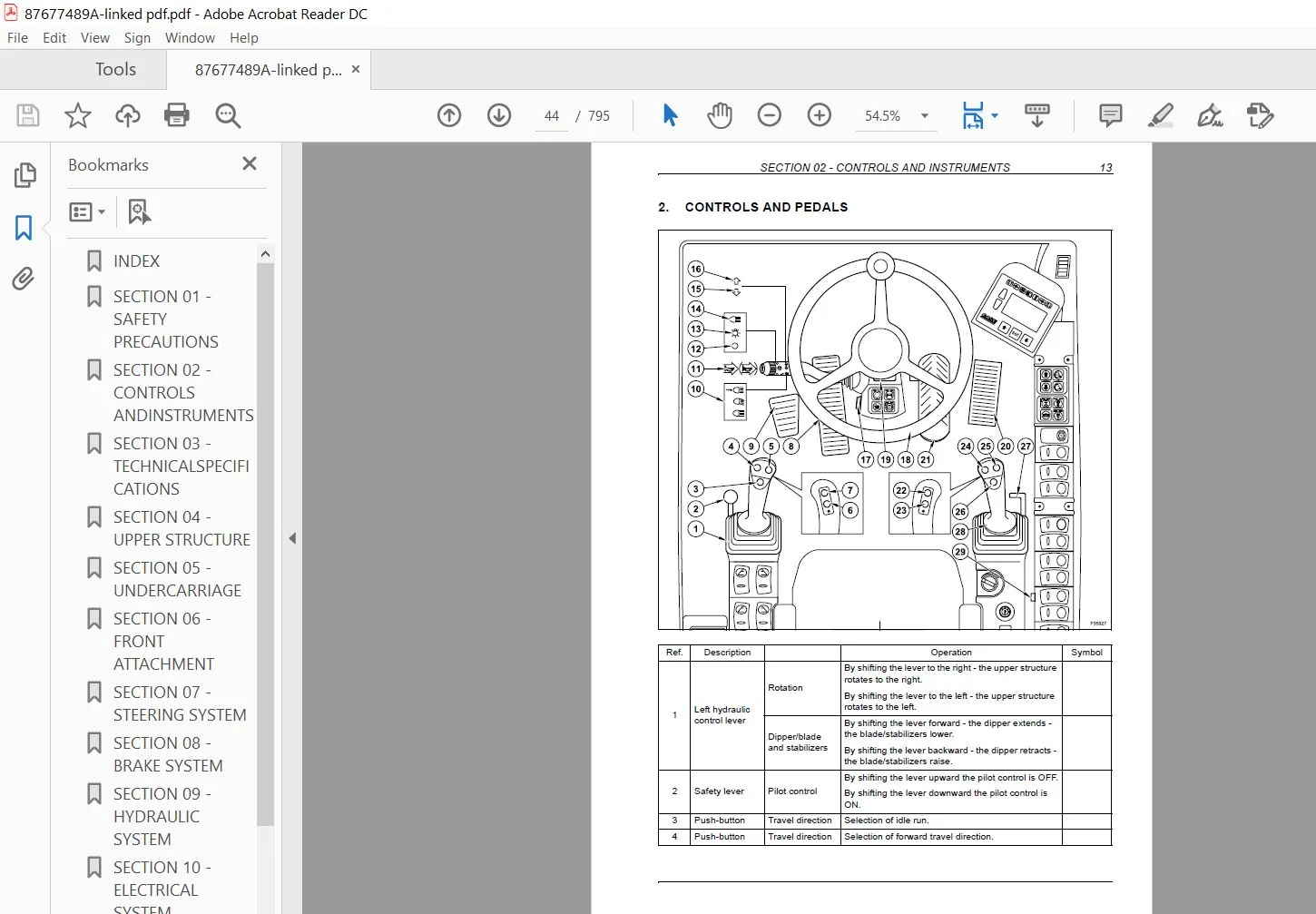
2 CONTROLS AND PEDALS 13
3 MULTI-FUNCTION DISPLAY 16
SECTION 03 – TECHNICAL SPECIFICATIONS
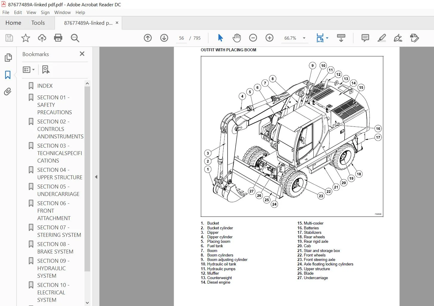
1 MAIN COMPONENTS 1
2 DIMENSIONS – OPERATING WEIGHTS 4
3 DIGGING PERFORMANCE 10
4 LIFTING CAPACITIES 20
5 HYDRAULIC SYSTEM 33
6 ROTATION 34
7 TRAVEL 35
7 1 TYRES 36
8 BRAKES 36
9 STEERING 36
10 ELECTRICAL SYSTEM 37
11 BUCKETS 37
12 TIGHTENING TORQUES 38
13 CENTRALIZED LUBRICATION PUMP (OPTIONAL) 38
14 FUEL SYSTEM 38
15 ENGINE 39
16 SUPPLY SUMMARIZING CHART 40
SECTION 04 – UPPER STRUCTURE
1 MAIN COMPONENTS 1
2 SLEWING BEARING 3
3 ROTATION GEARMOTOR 7
3 1 DISASSEMBLY AND ASSEMBLY 12
4 MULTI-COOLER 13
4 1 TECHNICAL SPECIFICATIONS 14
5 HYDRAULIC PUMPS 17
6 MUFFLER 18
7 HYDRAULIC OIL TANK 19
8 AIR FILTER 25
9 COUNTERWEIGHT 25
10 FUEL SYSTEM 26
11 CAB AND OPERATOR’S SEAT 32
11 1 CAB AT VARIABLE HEIGHT (WX 210 Industry – WX 240 Industry) 43
12 CENTRALIZED LUBRICATION PUMP 44
SECTION 05 – UNDERCARRIAGE
1 UNDERCARRIAGE COMPONENTS 1
2 REAR RIGID AXLE 2
2 1 TECHNICAL SPECIFICATIONS 3
2 2 DISASSEMBLY AND ASSEMBLY 6
2 3 DISASSEMBLY AND ASSEMBLY 8
2 4 TROUBLESHOOTING 87
2 5 SPECIAL TOOLS 89
3 TRAVEL MOTOR 90
3 1 TECHNICAL SPECIFICATIONS 90
3 2 DISASSEMBLY AND ASSEMBLY 91
3 3 DISASSEMBLY AND ASSEMBLY 92
4 CARDAN SHAFT 103
4 1 DISASSEMBLY AND ASSEMBLY 104
5 FRONT STEERING AXLE 106
5 1 TECHNICAL SPECIFICATIONS 107
5 2 DISASSEMBLY AND ASSEMBLY 110
5 3 DISASSEMBLY AND ASSEMBLY 112
5 4 TROUBLESHOOTING 184
5 5 SPECIAL TOOLS 186
6 WHEELS AND TYRES 187
7 BLADE 192
7 1 BLADE CYLINDER 194
8 AXLE FLOATING LOCKING CYLINDERS 202
8 1 TECHNICAL SPECIFICATIONS 203
8 2 DISASSEMBLY AND ASSEMBLY 204
8 3 AIR BLEEDING 205
8 4 DISASSEMBLY AND ASSEMBLY 206
8 5 TROUBLESHOOTING 208
9 STABILIZERS 209
9 1 STABILIZER CYLINDERS 212
9 2 TROUBLESHOOTING 222
10 LEFT LADDER 224
11 RIGHT LADDER AND TOOL STORAGE BOX 225
12 ROTARY CONTROL VALVE AND ELECTRIC ROTOR 226
12 1 TECHNICAL SPECIFICATIONS 226
12 2 DISASSEMBLY AND ASSEMBLY 227
12 3 DISASSEMBLY AND ASSEMBLY 228
12 4 ELECTRIC ROTOR 230
SECTION 06 – FRONT ATTACHMENT
1 TYPES OF FRONT ATTACHMENT 2
2 HYDRAULIC CYLINDERS 4
2 1 BOOM CYLINDER 6
2 2 DIPPER CYLINDER (WX 210 – WX 240) 16
2 3 DIPPER CYLINDER (WX 210 Industry – WX 240 Industry) 26
2 4 SPECIAL TOOLS 55
3 BUCKETS WX 210 – WX 240 56
4 WX 210 – WX 240 QUICK COUPLER 60
5 CLAMSHELL BUCKET 64
SECTION 07 – STEERING SYSTEM
1 OPERATION 1
2 POWER STEERING 3
2 1 DISASSEMBLY AND ASSEMBLY 5
3 PRIORITY VALVE 23
4 TROUBLESHOOTING 24
SECTION 08 – BRAKE SYSTEM
1 OPERATION 1
2 SERVICE BRAKE 4
3 PARKING BRAKE 7
4 PEDAL BRAKE VALVE 8
5 ACCUMULATORS 9
6 TROUBLESHOOTING 11
SECTION 09 – HYDRAULIC SYSTEM
1 HYDRAULIC SYSTEM 1
2 HYDRAULIC SYSTEM DIAGRAMS 5
2 1 HYDRAULIC SYSTEM DIAGRAMS – UPPER STRUCTURE 5
2 2 HYDRAULIC SYSTEM DIAGRAMS – UNDERCARRIAGE 21
2 3 HYDRAULIC SYSTEM DIAGRAMS BLADE AND/OR STABILIZERS 25
3 HYDRAULIC PUMPS 28
4 UPPER STRUCTURE CONTROL VALVE 48
5 UNDERCARRIAGE CONTROL VALVE 60
6 PILOT CONTROL ASSY 62
7 ROTATION SYSTEM 71
8 TRAVEL 75
9 STABILIZATION HYDRAULIC SYSTEM 87
10 BOOM HYDRAULIC SYSTEM 93
11 HYDRAULIC SYSTEM 100
12 HYDRAULIC SYSTEM OF DIPPER 106
13 HYDRAULIC SYSTEM OF PLACING BOOM 110
14 HYDRAULIC SYSTEM WITH COMBINATION OF DIFFERENT FUNCTIONS
(BOOM, PLACING BOOM, DIPPER AND BUCKET) 117
15 HYDRAULIC SYSTEM OF HAMMER (WITH PLACING BOOM) 119
16 HYDRAULIC SYSTEM OF HAMMER AND SHEARS (WITH PLACING BOOM) 122
17 HYDRAULIC SYSTEM OF SHEARS (WITH PLACING BOOM) 127
18 HYDRAULIC SYSTEM OF HAMMER (WITH MONOBOOM) 130
19 HYDRAULIC SYSTEM OF HAMMER AND SHEARS (WITH MONOBOOM) 133
20 HYDRAULIC SYSTEM OF SHEARS (WITH MONOBOOM) 138
21 TROUBLESHOOTING 141
SECTION 10 – ELECTRICAL SYSTEM
1 ELECTRICAL DIAGRAMS 1
1 1 WX 210 – WX 240 1
1 2 WX 210 Industry – WX 240 Industry 41
2 FUSES 80
3 BATTERIES 83
4 BULBS 87
5 TROUBLESHOOTING 91
SECTION 11 – ELECTRONICS
1 MAIN COMPONENTS 1
1 1 ELECTRICAL POWER SUPPLY DIAGRAM 3
2 COMPONENTS OF LINE 1 6
3 COMPONENTS OF LINE 2 10
3 1 TRAVEL PEDAL 16
3 2 ATTACHMENT PEDAL (PLACING BOOM AND HAMMER) 17
3 3 ELECTRO-HYDRAULIC SYSTEM 18
3 4 POWER CONTROL SYSTEM 19
4 ENGINE SPEED ACTUATOR 26
5 COOLANT TEMPERATURE DETECTION 27
6 CHARGE AIR TEMPERATURE DETECTION 28
7 HYDRAULIC OIL TEMPERATURE DETECTION 29
8 PROPORTIONAL VALVE – FAN MOTOR 30
9 PROPORTIONAL VALVES – CONTROL BLOCK 31
SECTION 12 – CALIBRATION
1 NECESSARY OPERATIONS BEFORE CALIBRATION 1
2 DISPLAY: CALIBRATION MENU 3
3 CALIBRATIONS WITH THE ENGINE RUNNING 4
3 1 VDO CALIBRATION 6
3 2 POWER CALIBRATION 8
3 3 MAIN VALVE CALIBRATION (CONTROL VALVE) 10
3 4 TRAVEL CALIBRATION 13
3 5 PUMP DELIVERY CALIBRATION 15
3 6 ROTATION PUMP CALIBRATION 18
3 7 AUXILIARY PRESSURE CALIBRATION 20
4 CALIBRATIONS WITH THE ENGINE STOPPED 22
4 1 CALIBRATIONS, ALL SOLENOID VALVES, MAIN PUMP, ROTATION PUMP,
AUXILIARY PRESSURE 24
4 2 MAIN VALVE CALIBRATION (CONTROL VALVE)
PLEASE NOTE:
⦁ This is the SAME manual used by the dealers to troubleshoot any faults in your vehicle. This can be yours in 2 minutes after the payment is made.
⦁ Contact us at [email protected] should you have any queries before your purchase or that you need any other service / repair / parts operators manual.


Augustine –