Description
Case IH Farmall 70JX 75JX 80JX 90JX 100JX 110JX Service Manual 48012897 2016
The Case IH Farmall 70JX 75JX 80JX 90JX 100JX 110JX Service Manual 48012897 2016 is a detailed workshop reference for servicing six Farmall JX tractor models. Across 884 pages it combines component descriptions, sectional drawings, specifications, tightening torques, adjustment data, special-tool information, hydraulic and electrical diagrams, troubleshooting material and illustrated step-by-step service operations.
Coverage extends from major mechanical work such as separating the engine and transmission, clutch overhaul and gearbox disassembly to axle, brake, hydraulic, steering, electrical, heating, air-conditioning and cab-related repairs. Procedures are supported by component illustrations that identify parts and working relationships, while technical-data sections provide the measurements and settings needed during inspection, adjustment and reassembly.
File Details
- Manual type: Service Manual
- Brand: CASE IH Agriculture
- Models: Farmall 70JX, Farmall 75JX, Farmall 80JX, Farmall 90JX, Farmall 100JX, Farmall 110JX
- Document number: 48012897
- Date: 21/12/2016
- Language: English
- Pages: 884
- File format: PDF
Workshop Procedures and Technical Data
This Case IH Farmall JX service manual is organized around individual tractor systems, with technical data and functional information placed alongside the service procedures they support. The engine section includes complete engine removal and installation operations, including disconnection of electrical, steering, fuel, cooling and Power-Shuttle connections, removal of the front axle drive shaft, support of the tractor and separation of the engine from the transmission.
The clutch material goes substantially beyond basic removal instructions. It covers hydraulic release control, clutch sectional views, specifications, tightening torques, special tools, removal, installation and overhaul. Different clutch arrangements used across the listed Farmall models are identified, including model-specific dimensions, driven-plate data, release clearances and adjustment procedures. The manual also explains PTO clutch servo operation and provides adjustment instructions for the hydraulic release control and PTO engaged switch.
Transmission coverage includes the mechanical transmission, internal components, Power-Shuttle transmission, gearbox, Power-Shuttle internal components, creeper and reverser. The mechanical transmission section documents a four-speed constant-mesh gearbox with synchronizers, range gearing and service measurements for shafts, bushings, gears and bearings. Procedures and sectional drawings support work on drive shafts, transfer-box components and electrohydraulic 4WD engagement. A dedicated troubleshooting section addresses conditions such as 4WD failing to engage or remaining engaged and links symptoms with possible electrical, hydraulic and mechanical causes.
Complete PDF Bookmark Tree
Complete Bookmarks
The complete bookmarks in the “Case IH Farmall 70JX 75JX 80JX 90JX 100JX 110JX Service Manual 48012897 2016” are as follows:
+INTRODUCTIONp. 5
+Note to the Ownerp. 7
General instructionsp. 7
Important noticep. 7
Shimmingp. 7
Rotating shaft sealsp. 7
O-ringsp. 7
Sealersp. 7
Bearingsp. 7
Roll pinsp. 7
Notes for spare partsp. 8
Notes for equipmentp. 8
Noticesp. 8
How to move the tractor with the battery removedp. 8
+Safety rulesp. 9
To prevent accidentsp. 9
Safety rulesp. 9
Generalitiesp. 9
Start upp. 10
Enginep. 11
Electrical systemsp. 11
Hydraulic systemsp. 11
Wheels and tiresp. 11
Removal and installationp. 11
+Safety rulesp. 12
Cab air conditioning systemp. 12
+Consumablesp. 13
COMPONENT TO BE FILLED OR TOPPED UPp. 13
QUANTITYp. 13
RECOMMENDED PRODUCTSp. 13
INTERNATIONAL SPECIFICATIONp. 13
+Enginep. 17
+Engine and crankcasep. 18
+Enginep. 22
Engine – Removep. 24
Engine – Installp. 32
+Clutchp. 37
+Clutch hydraulic release controlp. 38
+Clutch hydraulic release controlp. 42
+Clutch hydraulic release control – Sectional view (8000 Engine)p. 43
Cross-section of PTO servo controlp. 43
+Clutch hydraulic release control – Dynamic description (8000 Engine)
Engaging the PTO control clutch
Disengaging the PTO control clutchp. 47
+Clutch hydraulic release controlp. 42
+Clutch hydraulic release control – Adjust (8000 Engine)p. 48
Adjusting the PTO clutch servo controlp. 48
Adjusting the PTO engaged switchp. 49
+Clutch and componentsp. 38
+Clutchp. 52
+Clutch – General specification – (8000 Engine)p. 54
General specifications, clutch 11”/11”(Models Farmall® 80JX^^Farmall® 75JX^^Farmall® 70JX^^Farmall 70JX, Farmall 75JX and Farmall 80JXp. 54
General specifications, clutch 12”/11”(Model Farmall® 110JX^^Farmall® 100JX^^Farmall® 90JX^^ Farmall 90 JX, Farmall 100 JX and Farmall 110JX )p. 54
LUK 11”/11” ( Farmall® 80JX^^Farmall® 75JX^^Farmall® 70JX^^ Farmall 70JX , Farmall 75JX , Farmall 80JX models, see Clutch – Sectional view – (8000 Engine)18.110.AB-C.10.A.30 (Not for all markets) (Single lever P.T.O. option)p. 55
LUK 12”/11” (Farmall® 110JX^^Farmall® 100JX^^Farmall® 90JX^^ Farmall 90 JX, Farmall 100 JX and Farmall 110JX , see Clutch – Sectional view – (8000 Engine)18.110.AB-C.10.A.30) (Not for all markets) (Single lever P.T.O. option)p. 55
Clutch – Torque (8000 Engine)p. 55
Clutch – Special tools – (8000 Engine)p. 56
+Clutchp. 52
+Clutch – Sectional view – (8000 Engine)p. 57
Longitudinal section of clutchLUK 11”/11” (NAR market only)p. 60
Longitudinal section of the LUK 12”/11” clutch (NAR market only)p. 61
+Clutchp. 52
Clutch – Remove (8000 Engine)p. 62
Clutch – Install (8000 Engine)p. 70
+Clutch – Overhaul (8000 Engine)p. 72
Parts of the universal outfit 293650 necessary to adjust the VALEO clutchp. 72
Minimum permissible dimensions after refacing parts subject to wear for valeo clutchesp. 75
11”/11” dual clutchesp. 75
12”/12” dual clutchesp. 76
Adjusting the valeo clutchp. 76
Adjustment with clutch on benchp. 77
Adjustment with clutch fitted on engine flywheelp. 78
Adjusting the LUK clutchp. 79
Adjustment of the main clutch control linkagep. 79
PTO clutch linkage adjustment (valeo clutch)p. 80
PTO clutch linkage adjustment (LUK clutch)p. 80
Single Lever PTO (Not for all markets)p. 80
PTO clutch linkage adjustment (LUK clutch)p. 81
Single lever PTO (For NAR markets)p. 81
(CASE IH^^Farmall 90JX, Farmall 100JX and Farmall 110JX model)p. 81
+Transmissionp. 85
+Mechanical transmissionp. 86
+Mechanical transmissionp. 88
Mechanical transmission – General specification (12 x 4)p. 89
Mechanical transmission – Torque (12 x 4)p. 89
Mechanical transmission – Special tools (12 x 4)p. 91
+Mechanical transmission – Torque Drive linesp. 92
Main specificationp. 92
Main specification of drive shaftp. 92
+Mechanical transmission – Special tools Drive linesp. 93
+Mechanical transmission – General specification Drive linesp. 93
+Mechanical transmission – General specification – Electrohydraulic 4WDp. 93
Main specificationp. 93
Main specification of drive shaftp. 94
Main specifications – 4WD electrohydraulic engagementp. 94
Propeller shaft datap. 94
+Mechanical transmission – Torque – Electrohydraulic 4WDp. 95
Mechanical transmission – Special tools – Electrohydraulic 4WDp. 96
+Mechanical transmissionp. 88
Mechanical transmission – Sectional view (12 x 4)p. 97
Mechanical transmission – Static description (12 x 4)p. 101
Mechanical transmission – Sectional view Drive linesp. 102
+Mechanical transmission internal componentsp. 86
+Gears, shaft, and bearingsp. 106
Gears, shaft, and bearings – Sectional view – Electrohydraulic 4WD
+Transmission shaftp. 106
Transmission shaft – Disassemble Drive lines
Transmission shaft – Assemble Drive linesp. 113
Transmission shaft – Disassemble Electrohydraulic 4WDp. 114
Transmission shaft – Assemble Electrohydraulic 4WDp. 115
+Gears, shaft, and bearingsp. 106
Gears, shaft, and bearings – Remove Drive linesp. 116
Gears, shaft, and bearings – Install Drive linesp. 117
Gears, shaft, and bearings – Disassemble Drive linesp. 118
Gears, shaft, and bearings – Assemble Drive linesp. 119
Gears, shaft, and bearings – Remove Electrohydraulic 4WDp. 120
Gears, shaft, and bearings – Install Electrohydraulic 4WDp. 121
+Gears, shaft, and bearingsp. 106
Gears, shaft, and bearings – Troubleshooting Electrohydraulic 4WDp. 122
+Power shuttle transmissionp. 86
+Power shuttle transmissionp. 126
+Power shuttle transmission – General specification Power-Shuttle transmissionp. 127
Power-Shuttle main datap. 127
Power shuttle transmission – Special toolsp. 127
+Power shuttle transmissionp. 126
+Power shuttle transmission – Sectional viewp. 128
Longitudinal cross-sectional view of Power-Shuttle gearboxp. 128
Power-Shuttle control valvep. 129
+Power shuttle transmission – Static description Power-Shuttle transmissionp. 130
Gearbox and Power-Shuttlep. 130
Power-Shuttle modulep. 130
+Power shuttle transmissionp. 126
Power shuttle transmission – Test Power-Shuttle transmission
+Gearboxp. 86
+Gearboxp. 136
+Gearbox – Removep. 137
Rear transmission-Gearbox case removal-refittingp. 137
Gearbox – Installp. 146
+Gearbox – Removep. 148
Transmission-gearbox case removal-refittingp. 148
Gearbox – Installp. 154
+Gearbox – Adjustp. 157
Gearbox transmission casingp. 157
Adjusting the position of differential lock engagement sleevep. 157
+Power shuttle transmission internal componentsp. 86
+Clutchp. 162
+Clutch – Adjust Power-Shuttle transmissionp. 163
Clutch pedal control cablep. 163
Main Power-Shuttle control cablep. 163
+Gears, shaft, and bearingsp. 162
+Gears, shaft, and bearings – Disassemble – Power-Shuttle transmissionp. 164
Gearbox transmission casingp. 164
Gears, shaft, and bearings – Assemble Power-Shuttle transmissionp. 170
+Creeperp. 86
+Creeperp. 174
+Creeper – General specification – Reverser and creeper (20 x 12)p. 175
Synchroniser reverser-creeper unit main data 1p. 175
Creeper unit main datap. 175
Gearbox main datap. 175
Creeper – Torque Reverser and creeper (20 x 12)p. 175
Creeper – Special tools Reverser and creeper (20 x 12)p. 176
+Creeperp. 174
+Creeper – Sectional view Reverser and creeper (20 x 12)p. 179
Longitudinal section through reverser-creeper unitp. 179
Cross sectional views of synchroniser reverser-creeper unitp. 180
Creeper – Static description Reverser and creeper (20 x 12)p. 181
+Creeperp. 174
Creeper – Replace Reverser and creeper (20 x 12)p. 182
+Reverserp. 86
+Reverserp. 190
+Reverser – General specification (12 x 12)p. 191
Synchroniser reverser main datap. 191
Gearbox main datap. 191
Reverser – Torque (12 x12)p. 191
Reverser – Special tools (12 x 12)p. 192
+Reverserp. 190
Reverser – Sectional view (12 x 12)p. 193
Reverser – Static description (12 x 12)p. 194
+Reverserp. 190
Reverser – Replace (12 x12)p. 195
+Four-Wheel Drive (4WD) systemp. 201
+Four-Wheel Drive (4WD) gearboxp. 202
+Four-Wheel Drive (4WD) gearboxp. 204
Gears, shaft, and bearings – Disassemble Electrohydraulic 4WDp. 205
Gears, shaft, and bearings – Assemble Electrohydraulic 4WDp. 208
+Front axle systemp. 211
+Powered front axlep. 212
+Powered front axlep. 216
Powered front axle – General specificationp. 218
+Powered front axle – Torque (12 x 4)p. 221
Powered front axle – Special toolsp. 223
+Powered front axlep. 216
Powered front axle – Sectional viewp. 224
Powered front axle – Static descriptionp. 227
+Powered front axlep. 216
Powered front axle – Removep. 228
Powered front axle – Installp. 232
+Powered front axle – Removep. 233
CASE IH AGRICULTURE^^ Farmall 70JX and Farmall 80JX Modelsp. 233
Powered front axle – Installp. 235
+Powered front axle – Removep. 236
CASE IH^^FARMALL 75JX, FARMALL 90JX FARMALL 100JX and FARMALL 110JX Modelsp. 236
Powered front axle – Installp. 245
Powered front axle – Adjustp. 246
+Powered front axle – Overhaulp. 248
Limited-slip, self-locking differential lockp. 249
Operationp. 249
Front axle differential with limited-slip unitp. 250
Overhaulp. 250
Operationp. 253
Front axle differential with no spinp. 254
Overhaulp. 254
Checking the alignment of steering drive wheelsp. 255
Powered front axle – Removep. 257
Powered front axle – Installp. 260
Powered front axle – Overhaulp. 261
+Front bevel gear set and differentialp. 212
+Bevel gear set and differential carrierp. 268
+Bevel gear set and differential carrier – Adjustp. 269
Adjustment of the preload of the pinion shaft bearingsp. 269
Bevel drive adjustmentsp. 270
Determining the thickness of the drive pinion position adjustment shimp. 270
Examples (models CASE IH^^Farmall 70JX and Farmall 80JX )p. 270
Example 1p. 270
Example 2p. 271
Example 3p. 271
Bevel drive adjustmentsp. 272
Adjustment of the crown wheel bearings and checking the backlash between the pinion and crown wheelp. 272
+Final drive hub, steering knuckles, and shaftsp. 212
+Planetary drive and hubp. 278
+Planetary drive and hub – Removep. 280
Axle wheel hubp. 280
Removal-refittingp. 280
Planetary drive and hub – Installp. 284
+Steering knuckle and king pinp. 278
Steering knuckle and king pin – Replacep. 288
+Wheel hubp. 278
+Wheel hub – Adjustp. 289
First class axle mod. CASE IH^^FARMALL 70JX and FARMALL 80JXp. 289
+Wheel hub – Adjustp. 290
CASE IH^^Second class axle mod. FARMALL 75JX, FARMALL 90JX, FARMALL 100JX and FARMALL 110JXp. 290
+Rear axle systemp. 293
+Powered rear axlep. 294
+Powered rear axlep. 296
+Powered rear axle – General specificationp. 297
+Powered rear axle – Torquep. 298
Torque settings refer to Fig. img1p. 298
Powered rear axle – Special toolsp. 300
+Powered rear axlep. 296
+Powered rear axle – Sectional viewp. 303
Sectional drawings of transmission-gearbox casep. 303
Cross-sectional view of final drivep. 304
+Powered rear axle – Static description
Hydraulically controlled rear differential lockp. 307
+Rear bevel gear set and differentialp. 294
+Bevel gearp. 310
+Bevel gear – Adjustp. 311
Adjusting the bevel gear pairp. 311
Determining the bevel pinion positioning adjustment ringp. 311
Examples:p. 313
Adjusting the bevel gear pairp. 313
Adjusting the taper-roller bearings for pinion shaftp. 313
Bevel drive adjustmentsp. 314
Adjusting the ring bevel gear bearings and checking the clearance between the teeth of the bevel gear pair.p. 314
Adjusting the bevel gear pairp. 317
Differential pinion and side gear backlash adjustmentp. 317
+Rear bevel gear set and differentialp. 310
Rear bevel gear set and differential – Troubleshootingp. 321
+Differential lock hydraulic controlp. 310
Differential lock hydraulic control – Troubleshootingp. 322
+Final drive hub, steering knuckles, and shaftsp. 294
+Final drive hub, steering knuckles, and shaftsp. 326
+Final drive hub, steering knuckles, and shafts – Disassemblep. 327
Disassembly (cover) (final drive on tractor)p. 327
+Final drive hub, steering knuckles, and shafts – Assemblep. 330
+Final drive hub, steering knuckles, and shaftsp. 326
Final drive hub, steering knuckles, and shafts – Troubleshootingp. 333
+Power Take-Off (PTO)p. 337
+Rear mechanical controlp. 338
+Rear mechanical controlp. 340
+Rear mechanical control – General specificationp. 341
Mechanical power take-offp. 341
Farmall® 70JX^^Farmall® 80JX^^ Farmall 70JX and Farmall 80JXp. 341
Farmall® 90JX^^Farmall® 110JX^^Farmall® 100JX^^Farmall® 75JX^^Farmall 75JX, Farmall 90JX, Farmall 100JX and Farmall 110JXp. 341
Rear mechanical control – Special toolsp. 342
Rear mechanical control – Torquep. 343
+Rear mechanical controlp. 340
+Rear mechanical control – Sectional viewp. 344
Sectional diagrams of single- and 2-speed PTOp. 344
Sectional diagram of single- and 2-speed PTOp. 346
Sectional diagram of single- and 2-speed PTOp. 347
Section views – 540RPM/1000RPM PTO North American version (available on request), not synchronised with gearbox, with speed selection by replacement of splined output shaftp. 348
Section view of rigid coupling sleeve for single lever PTO (North American version, available on request), not synchronised with gearbox.p. 349
+Rear mechanical control – Dynamic descriptionp. 350
+Rear mechanical control – Dynamic descriptionp. 351
Power take-off operation of servo assist PTO (optional)p. 351
Independent power take-off servo assist PTO Fig. img1 and img2p. 351
Ground speed PTOp. 351
P.T.O speed selector lever 2 (Fig. img4)p. 352
+Rear mechanical control – Dynamic descriptionp. 353
Single lever power take-off (optional) Fig. img1 and Fig. img2p. 353
+Rear mechanical controlp. 340
Rear mechanical control – Removep. 354
Rear mechanical control – Installp. 357
+Rear mechanical control – Overhaulp. 358
Mechanical P.T.O. (540/750RPM P.T.O.) – bench Overhaulp. 358
Mechanical P.T.O. (540/1000 rpm P.T.O.) (interchangeable P.T.O. shaft) (NASO version) – Bench overhaulp. 360
+Brakes and controlsp. 369
+Brakes and controls generic sub-groupp. 370
+Brakes and controls generic sub-groupp. 372
Brakes and controls generic sub-group – General specificationp. 373
+Brakes and controls generic sub-group – Torquep. 373
Brakes and controls generic sub-group – Special toolsp. 374
+Brakes and controls generic sub-groupp. 372
Brakes and controls generic sub-group – Sectional viewp. 375
+Brakes and controls generic sub-group – Static descriptionp. 378
Service brakesp. 378
Parking brakep. 378
+Brakes and controls generic sub-groupp. 372
Brakes and controls generic sub-group – Troubleshootingp. 379
+Hydraulic service brakesp. 370
+Hydraulic service brakesp. 382
+Hydraulic service brakes – Sectional viewp. 383
Front live axle drive shaft brake (CASE IH^^Farmall 70JX and Farmall 80JX models)p. 383
+Hydraulic service brakes – Sectional viewp. 384
Front brake (Models CASE IH^^Farmall 75JX, Farmall 90JX, Farmall 100JX and Farmall 110JX)p. 384
+Hydraulic service brakesp. 382
Hydraulic service brakes – Remove – Front brakep. 385
Hydraulic service brakes – Overhaulp. 387
Hydraulic service brakes – Removep. 388
Hydraulic service brakes – Installp. 391
+Hydraulic service brakes – Removep. 393
Sectional drawing of service brake control pump (master cylinder)p. 395
Hydraulic service brakes – Installp. 396
Hydraulic service brakes – Bleedp. 397
+Brake cylinderp. 382
+Brake cylinder – Removep. 399
Hydraulic brake slave cylinderp. 399
Removal-refittingp. 399
+Brake cylinder – Installp. 400
Hydraulic brake slave cylinderp. 400
+Brake pedalsp. 382
+Brake pedals – Adjustp. 401
Service brake pedalsp. 401
Adjusting height of service brake pedalsp. 401
Sectional view of slave cylinderp. 402
+Parking brake or parking lockp. 370
+Hand brake leverp. 406
+Hand brake lever – Adjustp. 407
+Trailer brake hydraulic controlp. 370
+Trailer brake valvep. 410
Trailer brake valve – Sectional view – Auxiliary control valve
+Trailer brake valve – Dynamic description
Hydraulic diagram of trailer brake auxiliary control valve
Trailer brakes Off
Start of braking
Braking
+Trailer brake valvep. 410
Trailer brake valve – Adjust
+Hydraulic systemsp. 421
+Hydraulic systemsp. 422
+Hydraulic systemsp. 426
+Hydraulic systems – General specificationp. 428
Main specification of rear mechanical hydraulic liftp. 428
Main specification of implement hitching devicep. 429
Main specification of hydraulic pump (all models)p. 429
Filterp. 429
Pumpp. 429
Lift hydraulic pump (optional) datap. 430
Filterp. 430
Pumpp. 430
+Hydraulic systems – Torquep. 430
Hydraulic systems – Special tools – Hydraulic lift equipmentp. 431
+Hydraulic systemsp. 426
+Hydraulic systems – Sectional viewp. 432
Sectional drawing of hydraulic lift control valve block
+Hydraulic systems – Dynamic description
Hydraulic lift circuit
Arm lift phase
Neutral phase
Arm lowering phase
Hydraulic systems – Component localizationp. 442
+Hydraulic systemsp. 426
Hydraulic systems – Remove – Rear hydraulic lift assemblyp. 443
Hydraulic systems – Install – Rear hydraulic lift assemblyp. 448
Hydraulic systems – Disassemble – Rear hydraulic liftp. 449
Hydraulic systems – Assemble – Rear hydraulic liftp. 452
+Hydraulic systems – Adjust – Rear hydraulic liftp. 454
Adjusting position controlp. 454
Adjusting the maximum height of the lift armsp. 456
Adjusting draft controlp. 456
+Hydraulic systems – Adjustp. 461
Adjusting position control linkagep. 461
Adjusting draft control linkagep. 461
Adjusting LIFT-O-MATIC devicep. 462
+Hydraulic systems – Disassemblep. 464
Lift control valve block, detachedp. 464
Hydraulic systems – Assemblep. 468
Hydraulic systems – Removep. 469
Hydraulic systems – Installp. 470
+Safety and main relief valvesp. 422
+Relief valvep. 474
+Relief valve – Replace – Lift pressurep. 475
+Relief valve – Calibrate – Lift pressure relief valvep. 476
+Auxiliary hydraulic valves and linesp. 422
+Auxiliary hydraulic valves and linesp. 480
+Auxiliary hydraulic valves and lines – General specificationp. 481
+Auxiliary hydraulic valves and lines – Special toolsp. 481
+Auxiliary hydraulic valves and linesp. 480
Auxiliary hydraulic valves and lines – Sectional viewp. 482
+Auxiliary hydraulic valves and lines – Dynamic description
Operating stages of auxiliary control valve for operation of a double-acting cylinder with automatic detent release and float position
Float control operation
Operating stages of auxiliary control valve for operation a double-acting cylinder automatic detent release and float position
Lifting
Lowering
Operating stages of auxiliary control valve for operation of a double-acting cylinder (Fig. img4 & img5) and single-acting cylinder (Fig. img6 & img7)
Operating stages of auxiliary control valve operating a double-acting cylinder with automatic detent release
Lifting
Lowering
+Auxiliary hydraulic valves and linesp. 480
+Auxiliary hydraulic valves and lines – Disassemblep. 489
Convertible single/double-acting auxiliary control valvep. 489
Convertible single/double-acting auxiliary control valve with float control and detent releasep. 489
Double-acting auxiliary control valve with float control and automatic detent releasep. 496
+Auxiliary hydraulic valves and lines – Testp. 497
+Auxiliary hydraulic valves and lines – Leakage testp. 498
Spool leakage testp. 498
Valve leakage testp. 498
+Auxiliary hydraulic valves and lines – Adjustp. 500
Adjustment of the automatic detent release pressurep. 500
+Steeringp. 503
+Hydraulic control componentsp. 504
+Hydraulic control componentsp. 506
+Hydraulic control components – Torquep. 507
Principal datap. 507
Hydrostatic steeringp. 507
Control valvep. 507
Main specifications of hydraulic pump C25p. 507
Pumpp. 507
Cylinderp. 507
+Hydraulic control components – General specificationp. 508
Hydraulic control components – Special toolsp. 508
+Hydraulic control componentsp. 506
Hydraulic control components – Overview
+Hydraulic control components – Dynamic description
Operation
Neutral position
Steering to the right (Fig. img2)
Steering to the left
Steering to the right manually
Steering to the left manually
+Power steering control valvep. 506
Power steering control valve – Component localizationp. 513
+Hydraulic control componentsp. 506
Hydraulic control components – Removep. 514
Hydraulic control components – Installp. 517
Hydraulic control components – Disassemble – Hydrostatic steering control valvep. 518
Hydraulic control components – Assemblep. 523
+Hydraulic control components – Testp. 532
Test conditionsp. 532
Checking rotary valve wearp. 533
Checking return to neutral positionp. 533
Checking seal efficiencyp. 533
Setting the pressure relief valvep. 534
Checking the hydrostatic steering pressure relief valve with steering control valve installed on tractorp. 534
+Hydraulic control componentsp. 506
Hydraulic control components – Troubleshooting – Hydrostatic steeringp. 536
+Pumpp. 504
+Pumpp. 540
Pump – Component localizationp. 541
+Cylindersp. 504
+Steering cylinderp. 544
+Steering cylinder – Removep. 545
Front axle steering cylinderp. 545
+Steering cylinder – Removep. 547
Front axle steering cylinder (four wheel drive axle)p. 547
+Steering cylinder – Installp. 549
Front axle steering cylinderp. 549
+Wheelsp. 553
+Front wheelsp. 554
+Front wheelsp. 556
Front wheels – General specificationp. 557
+Front wheels – General specification MAIN DATAp. 559
MODELp. 559
TYRESp. 559
STANDART WHEEL TRACKSp. 559
aLTERNATİVE TRACK SETTINGp. 559
Ap. 559
Bp. 559
Cp. 559
Dp. 559
Ep. 559
Fp. 559
Farmall® 70JX^^Farmall 70 JXp. 559
Farmall® 80JX^^Farmall 80JXp. 559
Farmall® 75JX^^Farmall 75JXp. 559
Farmall® 90JX^^Farmall 90JXp. 559
Farmall® 100JX^^Farmall 100JXp. 559
Farmall® 110JX^^Farmall 110JXp. 559
+Front wheels – Torquep. 559
Torque settingsp. 561
Front axlep. 561
Front wheels – Special toolsp. 561
+Front wheelsp. 556
Front wheels – Sectional viewp. 562
+Front wheelsp. 556
+Front wheels – Checkp. 563
Checking the alignment of the front wheelsp. 563
+Front wheelsp. 556
Front wheels – Troubleshootingp. 564
+Cab climate controlp. 567
+Heatingp. 568
+Heatingp. 572
+Heating – Component identificationp. 573
Cab heating and ventilation controlsp. 573
Ventilation1. – Fig. img2 – img3p. 573
Fanp. 573
Air filterp. 574
Heating – Fig. img5p. 574
Ignition switchp. 574
+Air conditioningp. 568
+Air conditioningp. 578
+Air conditioning – General specificationp. 581
Cab air-conditioning system characteristicsp. 581
+Air conditioning – Special toolsp. 581
Tools required for servicing the air-conditioning systemp. 581
+Air conditioningp. 578
+Air conditioning – Dynamic descriptionp. 583
Operating principlesp. 583
Simplified psychrometric diagramp. 584
Simplified system diagramp. 585
+Air conditioning – Detailed viewp. 586
Schematic of air-conditioning systemp. 586
+Air conditioning – Static descriptionp. 587
Cab air-conditioning controlsp. 587
Switching on the air-conditioning and temperature controlp. 587
Heating control knob (Heating – Component identification50.100-C.40.C.20)p. 587
4-speed fan control knobp. 587
+Air conditioning – Static descriptionp. 588
Use of the air-conditioning systemp. 588
Switching On the air-conditioningp. 588
Adjustmentp. 588
Switching Off the air-conditioning systemp. 588
+Air conditioning – Component identificationp. 589
Axial flow reciprocating piston compressor SANDEN SD 7H15p. 589
Compressorp. 589
SANDEN SD 7H15p. 589
Condenserp. 589
Receiver-drierp. 590
Thermostatic expansion valvep. 590
Expansion valve blockp. 591
Thermostatic switch (ANTIFROST)p. 591
Evaporatorp. 591
+Air conditioningp. 578
Air conditioning – Service instruction – Fehlersuchep. 593
+Air conditioning – Service instructionp. 597
Warnings regarding servicing and repair of the air-conditioning systemp. 597
Refrigerant recovery-recycling and evacuation-charging stationsp. 597
Recovery and recycling station (294048)p. 598
Description (Refer to Air conditioning – Check50.200-F.40.A.11)p. 598
Technical characteristicsp. 598
Maintenancep. 598
Replacement of refrigerant decontamination filter 3p. 598
Check filter connections for leaks 3p. 599
Changing the compressor oil in the recovery/recycling stationp. 599
Evacuation/charging station (294030)p. 600
Description (Refer to Air conditioning – Check50.200-F.40.A.11)p. 600
Technical characteristicsp. 600
Maintenancep. 600
Check level and change oil in pump of evacuation/charging station (periodic check)p. 600
+Air conditioning – Checkp. 601
Dehydration, recharging and refrigeration checkp. 601
Recycling recovered refrigerantp. 602
Discharge of recovered oilp. 604
Transfer of decontaminated refrigerant from cylinder 10 to an external cylinderp. 604
Evacuation of the graduated cylinder 31 of the evacuation/charging stationp. 605
Charging the graduated cylinder 31 of the evacuation/charging stationp. 605
Evacuation/charging stationp. 606
Charging the cab air conditioning system (after evacuation) with new oilp. 608
Charging the cab air-conditioning system with refrigerant (after evacuation)p. 609
+Air conditioning – Testp. 610
Function testing of cab air-conditioning systemp. 610
+Air conditioning – Chargingp. 612
Summary of the air-conditioning system charging operationsp. 612
Air-conditioning system operating temperature variationsp. 613
+Air conditioning – Checkp. 614
Checking for refrigerant leaks using an electronic leak detectorp. 614
Leak detector (294036)p. 614
Usep. 614
Refrigerant leak testp. 614
Maintenancep. 614
Leak detector probep. 615
Air-conditioning systemp. 615
Testing for leaks with leak detector 294036 and elimination of leaksp. 615
Air-conditioning system fault diagnosis summaryp. 615
Visual inspection of componentsp. 616
+Air conditioning – Service instructionp. 617
Maintenance of the air-conditioning systemp. 617
Schematic of the air-conditioning systemp. 618
+Air conditioning – Replacep. 619
Air-conditioning and heating pipesp. 619
+Air-conditioning compressorp. 578
Air-conditioning compressor – Removep. 622
+Air-conditioning compressor – Installp. 624
Compressor oil – type and quantityp. 624
+Compressor drive beltp. 579
+Compressor drive belt – Adjustp. 625
Tension adjustmentp. 625
Fitting the compressor drive beltp. 625
Checking compressor drive belt tensionp. 625
Periodic checking of drive beltp. 626
+Air-conditioning condenserp. 579
Air-conditioning condenser – Replacep. 627
+Receiver-dryerp. 579
Receiver-dryer – Replacep. 628
+Electrical systemsp. 633
+Electrical systemp. 634
+Electrical systemp. 636
+Electrical system – Dynamic descriptionp. 637
Transmitters, sensors and switchesp. 637
A. Main fuse boxp. 637
B. Batteryp. 637
C. Alternatorp. 637
D. Transmission clutch pedal switchp. 637
E. Transmission Power-Shuttle neutral position switchp. 637
F. Air cleaner clogged sensorp. 637
G. Water in fuel sensorp. 637
H. Engine oil pressure switchp. 637
I. Fuel tank level transmitterp. 637
J. Engine coolant temperaturep. 637
K. Brake light switchesp. 637
L. Brake oil level switchp. 637
M. Parking brake switchp. 637
N. Turn signal flashor (for NAR market only)p. 638
O. Turn signal flashorp. 638
P. PTO clutch lever disengaged switchp. 638
Transmitters and switches
+Electrical system – Static descriptionp. 644
Multi-function controlp. 644
Direction indicatorsp. 644
Flashing front headlightsp. 644
Side lightsp. 644
Dipped headlightsp. 644
Main beam headlightsp. 644
Hornp. 644
+Harnesses and connectorsp. 634
+Harnesses and connectorsp. 648
Harnesses and connectors – Overviewp. 649
+Wiring harnessesp. 648
Wiring harnesses – Electrical schematic sheet 01 Centre (8000 series engines w/out cab)p. 654
+Wiring harnesses – Electrical schematic sheet 03 Center (8000 series engines with cab)
+Wiring harnesses – Electrical schematic sheet 05
+Wiring harnesses – Electrical schematic sheet 06
Starting circuit (Nef & F5A series engine)
+Wiring harnesses – Electrical schematic sheet 07
Direction indicator and hazard warning light circuit
+Wiring harnesses – Electrical schematic sheet 08
Windscreen and rear window wiper/washer circuit
+Wiring harnesses – Electrical schematic sheet 09
+Wiring harnesses – Electrical schematic sheet 10
Heating and air-conditioning system circuit (For 8000 series engines)
Wiring harnesses – Electrical schematic sheet 12 – Work lamp (with cab) circuit
Wiring harnesses – Electrical schematic sheet 13 – Work lamp (w/out cab) circuit
+Wiring harnesses – Electrical schematic sheet 14
Main and dipped headlights, horn
+Wiring harnesses – Electrical schematic sheet 15
+Wire connectorsp. 648
+Wire connectors – Component diagram 01p. 710
Analogue instrument clusterp. 711
Connector Ap. 712
Connector Bp. 712
Wire connectors – Component diagram 02p. 713
+Wire connectors – Component diagram 03p. 716
Wire connectors – Component diagram 04p. 721
+Wire connectors – Component diagram 05p. 724
+Wire connectors – Component diagram 06p. 728
+Wire connectors – Component diagram 07p. 730
+Wire connectors – Component diagram 08p. 735
+Wire connectors – Component diagram 09p. 740
+Fuse and relay boxp. 648
Fuse and relay box – Overviewp. 745
+Fuse and relay box – Static descriptionp. 747
Electrical wire colour codingp. 748
+Engine starting systemp. 634
+Engine starting systemp. 752
+Engine starting system – General specificationp. 753
Technical informationp. 753
+Engine starting system – Torquep. 753
+Engine starting systemp. 752
+Engine starting system – Static descriptionp. 754
Description and operationp. 754
+Engine starting system – Electrical schemap. 755
+Engine starterp. 752
Engine starter – Component localizationp. 764
+Engine starting systemp. 752
+Engine starting system – Testp. 765
Power absorption in starter motor circuit (Fig. img1)p. 765
Resistance in ignition system circuit (voltage drop) (Fig. img3)p. 765
Positive battery cablep. 766
Starter motor earth (ground) (Fig. img3)p. 766
Battery earth (ground) cable (Fig. img4)p. 766
+Engine starterp. 752
Engine starter – Replacep. 767
+Engine starter – Disassemblep. 768
+Engine starter – Assemblep. 769
Armature shaft end playp. 769
+Engine starter – Testp. 770
Starter motor test without load (Fig.img1)p. 770
Bench testsp. 770
Armature (Fig. img2)p. 770
Field windings (Fig. img3)p. 771
Bearing bushingsp. 771
Driving pinionp. 771
+Alternatorp. 634
+Alternatorp. 774
+Alternator – General specificationp. 775
Technical informationp. 775
+Alternator – Torquep. 775
+Alternatorp. 774
+Alternator – Static descriptionp. 776
Alternator descriptionp. 776
Alternator charging circuitp. 776
Alternator functioningp. 777
Fan belt tensionerp. 777
+Alternatorp. 774
+Alternator – Testp. 778
Precautionsp. 778
Preliminary checksp. 778
Checking the batteryp. 778
Checking the driving beltp. 778
Checking the warning lightp. 779
Preliminary testsp. 779
Alternator wire connections testp. 780
Charging current and regulated voltage testsp. 780
Charging circuit voltage drop testsp. 781
Insulated side voltage drop testp. 781
Ground side voltage drop testp. 781
Maximum alternator output testp. 782
Alternator component testsp. 782
+Alternator – Removep. 783
Removing the alternatorp. 783
Alternator componentsp. 784
Rotor and regulator field circuit testp. 785
Checking the continuity of three stator windingsp. 785
Checking the diodesp. 786
Excitation diodes testp. 786
Positive power diodes testp. 787
Negative power diodes testp. 787
Rotorp. 787
Check on rotor winding resistance measured between pins connected to brushesp. 787
+Alternator – Disassemblep. 788
Electronic voltage regulator (Fig. img3)p. 788
Inductor coil insulation testop. 789
Check rotor inductor resistance on slip ringsp. 790
Alternator – Assemblep. 791
Alternator – Service instructionp. 792
Alternator – Installp. 793
+Batteryp. 634
+Batteryp. 796
+Battery – General specificationp. 797
Technical informationp. 797
+Batteryp. 796
+Battery – Static descriptionp. 798
Description and operationp. 798
+Batteryp. 796
+Battery – Removep. 799
Located on top of front axle support (Fig. img1)p. 799
+Battery – Installp. 800
Applicable to all types of batteryp. 800
+Battery – Service instructionp. 801
Relative densityp. 801
Battery maintenancep. 802
Dry charged batteriesp. 802
Charging the batteryp. 802
Normal charging (top up)p. 803
Charging very flat batteriesp. 803
Testsp. 804
Performance testsp. 805
Battery problems – frequent causesp. 806
+Cab controlsp. 634
+Cab controlsp. 810
+Cab controls – Static descriptionp. 811
Right-hand pillar (Fig. img1)p. 811
Front windscreen wiper/washer button 1p. 811
Rear window washer switch 2p. 811
Front work lights switch 3p. 812
Rear work lights switch 4p. 812
Roof beacon switch (with cab) 5p. 812
Rear windscreen wiper Fig. img4 (optional)p. 812
Beacon lamp (without cab) – Fig. img5p. 812
+Wiper and washer systemp. 634
+Windshield wiper motorp. 816
Windshield wiper motor – Disassemblep. 817
+Warning indicators, alarms, and instrumentsp. 634
+Instrument clusterp. 822
+Instrument cluster – Static descriptionp. 823
Fuel level gauge (Fig. img4)p. 824
Proof meter (Fig. img4)p. 824
Engine coolant temperature gauge (Fig. img5)p. 825
Instrument panel and console controlsp. 825
Instrument console controls (Fig. img8)p. 826
Ignition key (Fig. img9)p. 826
Console controls (Fig. img10)p. 826
+Platform, cab, bodywork, and decalsp. 831
+Cabp. 832
+Cabp. 834
Cab – Disassemblep. 835
Cab – Assemblep. 843
+Cab interiorp. 832
+Cab interiorp. 848
Cab interior – Disassemblep. 849
Cab interior – Assemblep. 855
+Cab doors and hatchesp. 832
+Cab doors and hatchesp. 858
+Cab doors and hatches – Disassemblep. 859
Rear window, handle and lockp. 859
+Cab doors and hatches – Assemblep. 860
Rear window, handle and lockp. 860
Cab doors and hatches – Disassemblep. 861
Cab doors and hatches – Assemblep. 862
Cab doors and hatches – Removep. 863
Cab doors and hatches – Installp. 864
+Cab door handlep. 858
+Cab door handle – Disassemblep. 865
Lock and exterior handle LH doorp. 865
+Cab door handle – Assemblep. 866
Lock and exterior handle LH doorp. 866
+Machine shields and guardsp. 832
+Machine shields and guardsp. 870
Machine shields and guards – Assemblep. 871
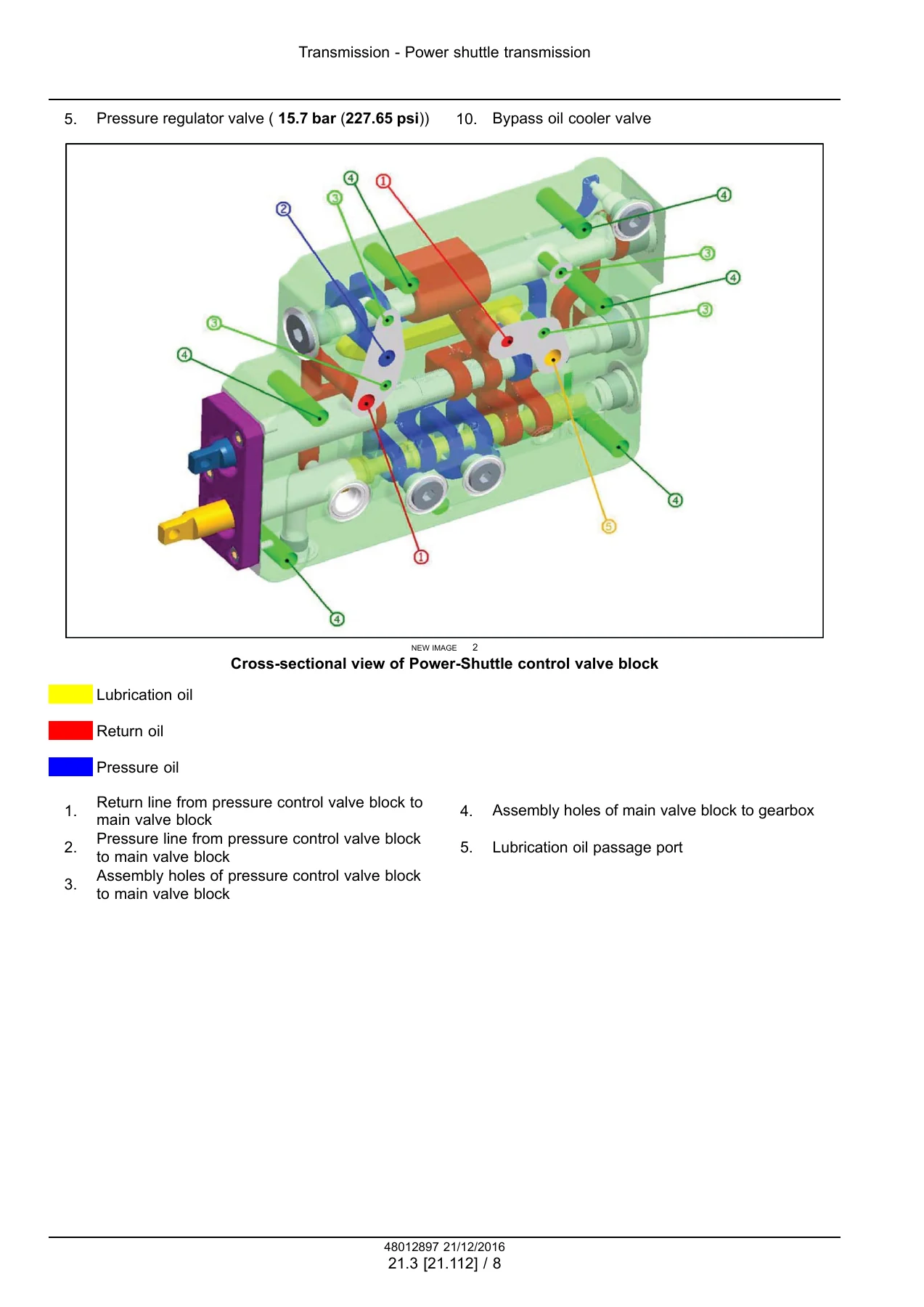
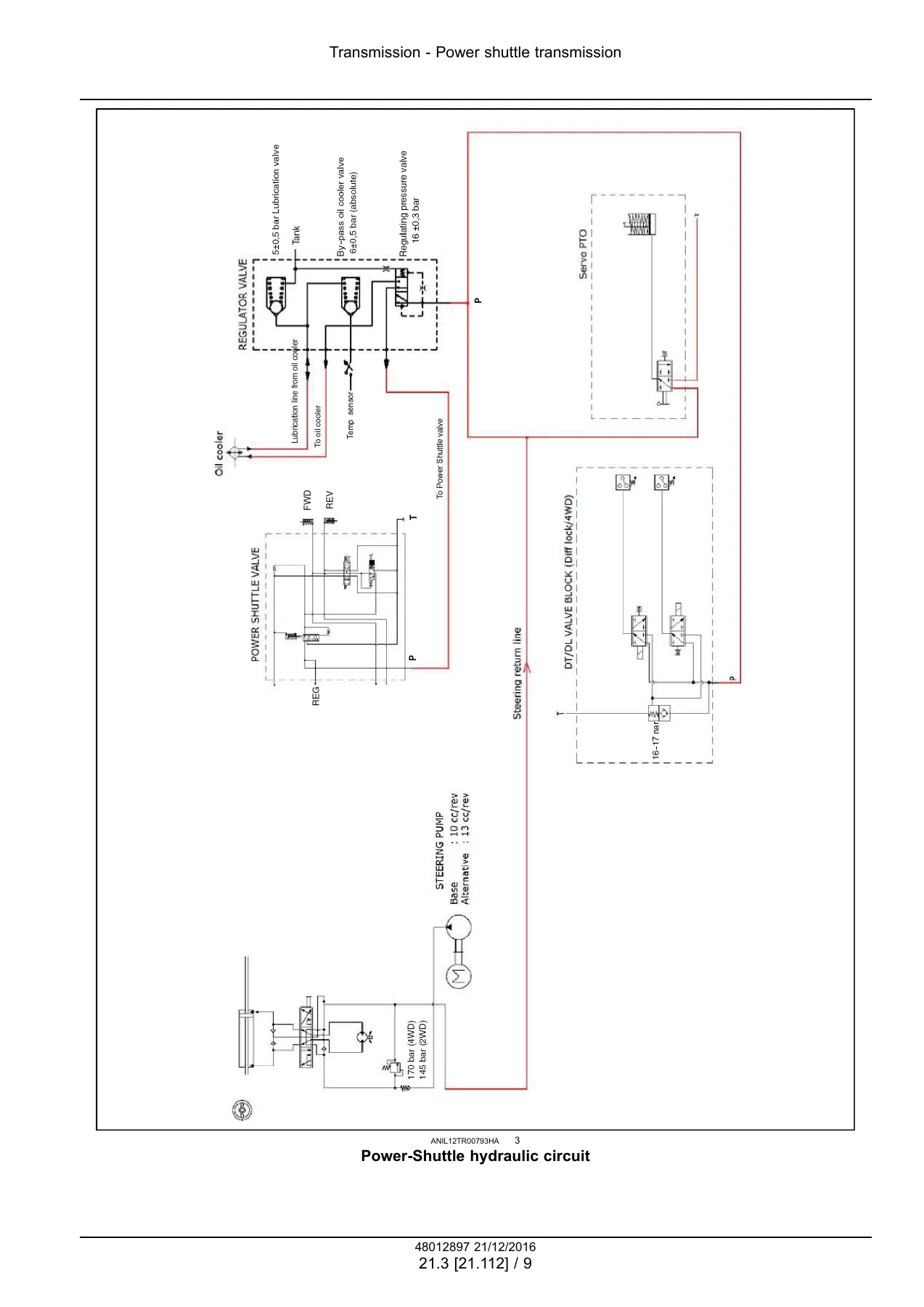
The Power-Shuttle material includes sectional views of the forward and reverse clutch system, the control valve and hydraulic circuit. The manual describes hydraulic multi-plate oil-immersed clutch packs, control-valve operation and pressure testing. It gives procedures for adjusting the clutch pedal control cable and main Power-Shuttle control cable, as well as disassembly and assembly of internal clutch, shaft and bearing components. Reverser and creeper chapters add specifications, torque data, sectional views and replacement procedures for the related gear and synchronizer assemblies.
Model-Specific Fluids, Settings and Service References
The introductory service data includes a consumables chart with capacities that vary by model and configuration. The cooling system is listed at 11 L without cab and 13 L with cab for all models, while the fuel tank capacity is 110 L. Engine-sump capacities are separated between the Farmall 70JX/80JX group and the 75JX/90JX/100JX/110JX group, both with and without the oil filter. Front axle housing and final-drive capacities are likewise differentiated by model. The combined rear transmission, gearbox, hydraulic lift and PTO capacity is listed as 43 L, and rear final-drive quantities are also identified by tractor model.
Throughout the manual, service-data tables provide precise values for clearances, shims, spring loads, bearing adjustments, backlash, operating pressures and tightening torques. For example, the hydraulic clutch-control description includes operating pressure information, the Power-Shuttle section provides regulated pressure and pressure-test procedures, and the hydraulic chapters specify relief-valve checks. These values are integrated with the related service instructions so technicians can inspect components against the values given for the system being repaired.
Chapters Covered
- Introduction
- Note to the Owner
- Safety rules
- Consumables
- Engine
- Clutch
- Clutch hydraulic release control
- Clutch and components
- Transmission
- Mechanical transmission
- Mechanical transmission internal components
- Power shuttle transmission
- Gearbox
- Power shuttle transmission internal components
- Creeper
- Reverser
- Four-Wheel Drive (4WD) system
- Four-Wheel Drive (4WD) gearbox
- Front axle system
- Powered front axle
- Front bevel gear set and differential
- Final drive hub, steering knuckles, and shafts
- Rear axle system
- Powered rear axle
- Rear bevel gear set and differential
- Final drive hub, steering knuckles, and shafts
- Power Take-Off (PTO)
- Brakes and controls
- Brakes and controls generic sub-group
- Hydraulic service brakes
- Parking brake or parking lock
- Trailer brake hydraulic control
- Hydraulic systems
- Hydraulic systems
- Safety and main relief valves
- Auxiliary hydraulic valves and lines
- Steering
- Hydraulic control components
- Pump
- Cylinders
- Wheels
- Cab climate control
- Electrical systems
- Electrical system
- Harnesses and connectors
- Engine starting system
- Alternator
- Battery
- Cab controls
- Wiper and washer system
- Warning indicators, alarms, and instruments
- Platform, cab, bodywork, and decals
- Cab
- Cab interior
- Cab doors and hatches
- Machine shields and guards
Taken together, these chapters make the Farmall 70JX through 110JX service manual useful for both major component work and system-level diagnosis. The manual moves from functional descriptions and specifications into practical removal, installation, disassembly, assembly, adjustment, testing and overhaul instructions. Numerous sectional views and component diagrams clarify internal construction, while the electrical section includes harness and connector information along with multiple electrical schematic sheets for tractor configurations with and without a cab.
Axles, Brakes, Hydraulics and Steering
Front and rear axle sections provide technical data for bevel gears, differentials, final drives, bearings and adjustment components. The front axle chapter includes model-dependent gear ratios and backlash values as well as removal, installation, adjustment and overhaul operations. Rear axle information similarly combines specifications and torque settings with sectional views and service references for differential and final-drive work.
The braking chapters cover hydraulic service brakes, parking brake or parking lock and trailer brake hydraulic control. Different front-brake arrangements are illustrated for the Farmall model groups, with component sectional views and service instructions. Hydraulic-system coverage includes the rear hydraulic lift, relief valves and auxiliary control valves. The manual explains auxiliary valve operation for external hydraulic loads, provides sectional views of valve components and includes testing procedures. Steering chapters then address hydraulic control components, the pump and steering cylinders.
Electrical, Climate Control and Cab Service
A substantial electrical section covers the overall electrical system, harnesses and connectors, starting system, alternator, battery, cab controls, wiper and washer system, and warning indicators and instruments. Wiring-harness material includes multiple electrical schematic sheets, including configurations identified for 8000 series engines with and without cab. These diagrams provide a valuable reference when tracing circuits, connectors and electrical components during fault finding or repair.
Cab climate control is divided into heating and air conditioning, while the final body-related chapters address the cab, cab interior, doors and hatches, plus shields and guards. This means the Case IH Farmall 70JX 75JX 80JX 90JX 100JX 110JX Service Manual 48012897 2016 remains useful beyond drivetrain work when service requires access to operator-station components, climate-control equipment or electrical systems.
Repair Your Farmall JX with the Correct Procedures and Specifications
For owners and technicians working on a Farmall 70JX, 75JX, 80JX, 90JX, 100JX or 110JX, this manual provides the procedures and numerical service data needed for jobs ranging from clutch and transmission work to axle repairs, hydraulic testing, brake service, steering repairs and electrical diagnosis. Using the specified measurements, torque values, clearances, pressures, adjustment procedures and illustrated component layouts helps service work follow the documented method rather than relying on guesswork.
The Case IH Farmall 70JX 75JX 80JX 90JX 100JX 110JX Service Manual 48012897 2016 is supplied as an instant PDF download after payment. There is no physical book and no shipping delay. Open the manual on a compatible computer, tablet or phone, keep it available in the workshop, and print the pages or procedures you need for the repair at hand.

Reviews
There are no reviews yet.