
Case Steyr T7200 L Transmission Training Manual – Power Shift, Power Shuttle & OC-LS Hydraulics for 9105a, 9115a, 9125a, 9145a, CS110, CS120, CS130, CS150
Original price was: $59.95.$39.95Current price is: $39.95.
304-page Case Steyr T7200 L transmission training manual covering the power shift gearbox, main clutch, Power Shuttle, 6-speed synchronous gearbox, rear axle and brakes, PTO gearbox and OC-LS hydraulic system for 9105a, 9115a, 9125a, 9145a, CS110, CS120, CS130 and CS150 tractors.
Description
File Details
- Manual type: Technical Training Manual (HOW IT WORKS)
- Brand / Manufacturer: Case Steyr (Case Steyr Landmaschinentechnik GmbH)
- Models covered: 9105a, 9115a, 9125a, 9145a, CS110, CS120, CS130, CS150 (T-7224 L, T-7226 L, T-7228 L)
- Language: English
- Page count: 304
- File format: PDF
- Document number: 7-95450EN
- Edition / Date: Training Center St. Valentin, May 1999
Chapters Covered
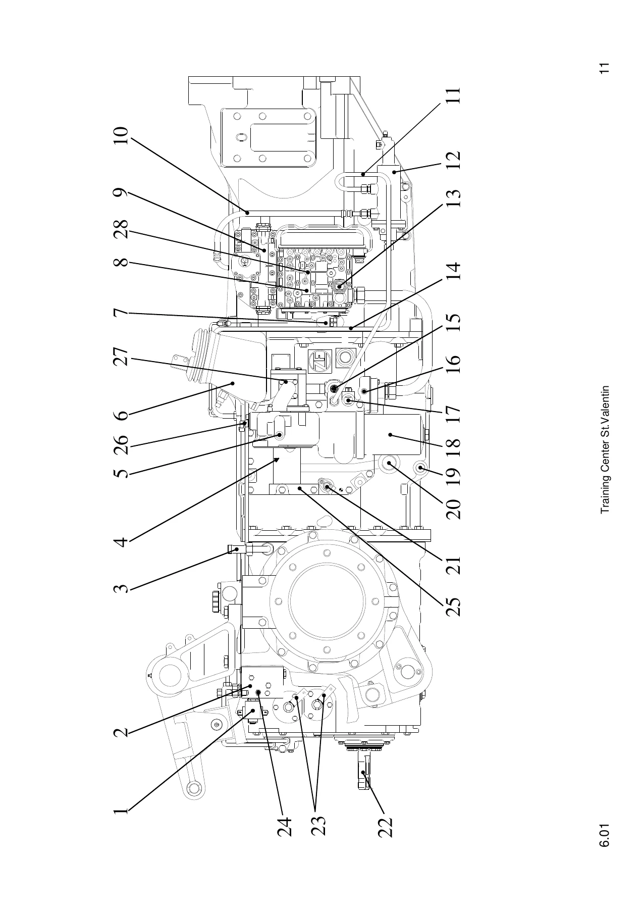
- 6.01 Gearbox – Assembly
- 6.02 Oil System
- 6.03 Main Clutch (Driving Clutch)
- 6.04 Gearbox Section
- 6.05 Power Shift Gearbox – Operation
- 6.06 Hydr. Power Shift Control Block
- 6.07 6 Speed Synchronous Gearbox
- 6.08 Rear Axle, Brakes
- 6.09 Power Take Off (PTO) Gearbox
- 6A Power Shuttle (Supplement to Section 6)
- Section 8 – OC-LS Hydraulic System (Open Center – Load Sensing with Constant Displacement Pump)
6.01 Gearbox – Assembly
The aggregate layout chapter maps the complete power unit module: vibration damper, power shift gearbox, crawler gear range (optional), main clutch, 6-speed synchronous gearbox, rear axle, differential, planetary gear unit, brakes, 4-wheel drive (MFD), APL 4-wheel planetary steering axle, PTO shaft gear unit, rear PTO shaft and PTO shaft clutch, plus optional front PTO. It also covers aggregate/type allocation, parts list number decoding and the speed-ratio bands for 40 km/h and 50 km/h versions.
6.02 Oil System
This section covers the common oil supply shared with the power shift gearbox and 6-speed synchronous gearbox, capacity figures, the approved oil list (TE-ML06), oil and filter change intervals, oil level viewing glass, and the oil cooling circuit. It details the 3-way thermostatic control valve, oil-to-cooler lines, the lubricating pressure limiting valve (pmax = 4 bar), and towing precautions — including required gearbox level positions and the 8 bar system pressure requirement.
6.03 Main Clutch (Driving Clutch)
The driving clutch chapter describes layout and design characteristics, hydrostatic lubrication, first- and second-version operation, disengaging and engaging function, and the clutch booster. Master and slave cylinder circuits for circuits I and II are shown with bleeding sequences, booster rest/middle/end positions, component lists and exploded cross-sections with part numbers. Fitting instructions cover lining disk soaking, axial play (0.2 + 0.1 mm) and the 18 bar P1 feed to the booster.
6.04 Gearbox Section
Gearbox lubrication, longitudinal cross-section design, the power shift clutch arrangement (clutches A–G), 4-wheel drive, and the super crawler gear (SGK) are covered here. The chapter explains how the SGK is synchronised, the shift pin arrangement between the shafts, and ratio differences between 40 km/h and 50 km/h versions. Gearbox layout diagrams with tooth counts are provided for the T7224L/9105/CS110, T7226L/9115/9125/CS120/CS130 and T7228L/9145/CS150.
6.05 Power Shift Gearbox – Operation
Forward and reverse power flow are broken down by stage (I–IV), showing which clutches engage, the tooth meshing involved, and the resulting ratio. P1 pressure is applied to clutch C at engine start; the power shift gearbox sits in neutral until a direction is selected. The chapter includes ratio tables, clutch engagement charts and gearbox layout diagrams with number of teeth for each tractor model and speed version.
6.06 Hydr. Power Shift Control Block
The control block chapter covers modular construction, EFR functions, the opto-acoustic indicator lamp, forward/reverse pre-selection and the pressure modulation system. It explains starting pressure, pressure gradient (limited to 10 bar per second), hard versus soft shift, and the field/road mode changeover. Internal components — modulation valve, control slide, cocking slider, bleed valve, rest valve, two-stage piston, push rod, reversing valve, solenoid valve, control slider M1, bleeder valve E, return slider R — are described and illustrated. Tightening torques (23 Nm for the control block, 25 Nm for the locking block), seal handling and troubleshooting notes are included.
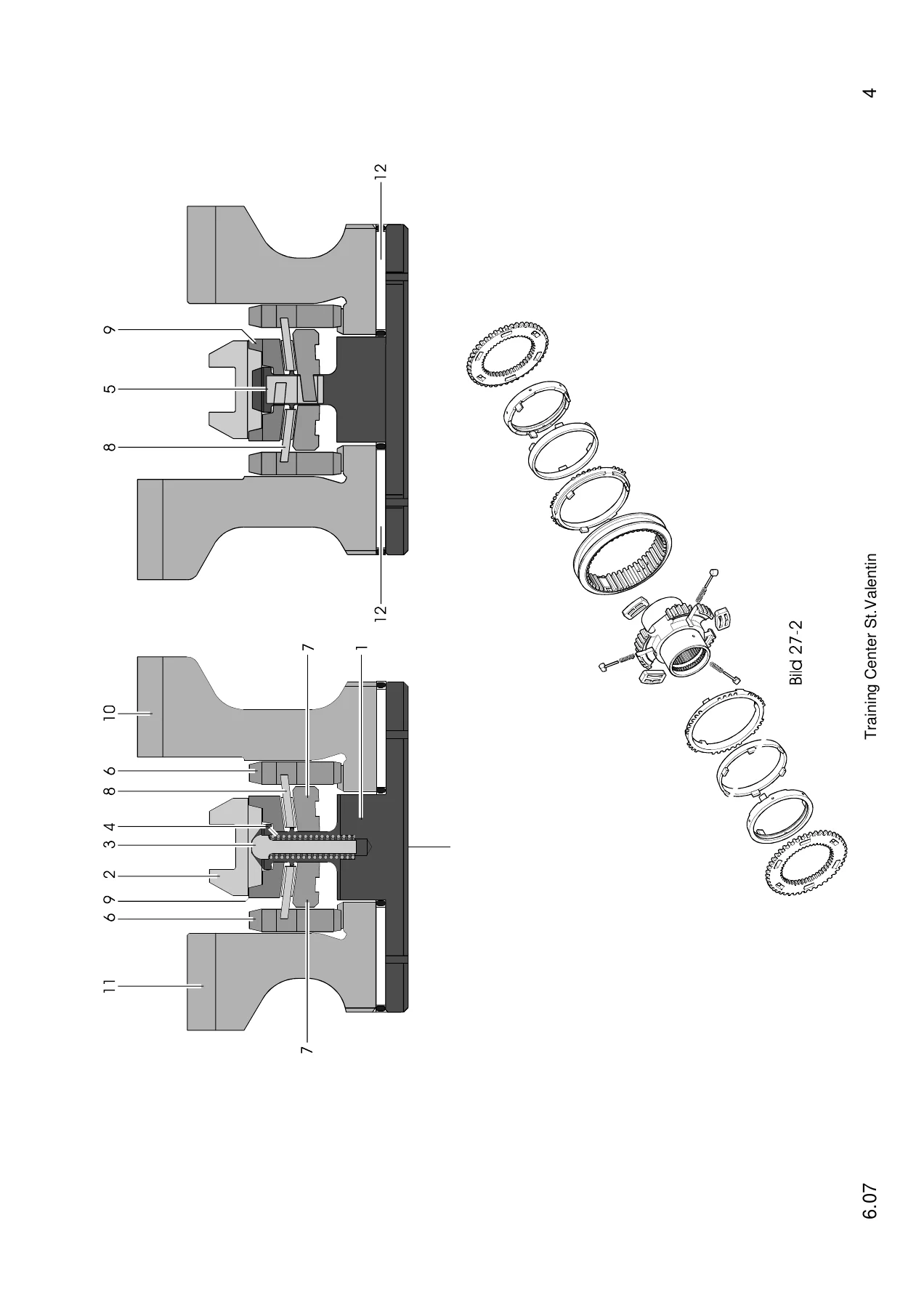
6.07 6 Speed Synchronous Gearbox
This chapter explains the traditional two-shafted design (countershaft and main shaft), tapered roller bearings, movable wheels on the shafts, and shift forks with borax-alloy sliding shoes. Shift positions and adjustment are covered, along with the crawler gear shifting area (14.5 + 0.1 mm), the bevel pinion adjustment (K = 0.76 – 0.03/+0.03) and the differential master gear. Tightening torques for the housing flange, bearing covers, countershaft, rear axle and 4-wheel drive clutch are tabulated.
6.08 Rear Axle, Brakes
Rear axle assembly (bevel pinion, differential, brake, axle stub, planetary gearbox final drive, tapered roller bearings, cartridge sealing rings), pressure lubrication and brake operation are covered. The brake system chapter describes the multi-disc brake, parking brake, working brake and the brake booster — construction, initial position, and operation with the engine running and at a standstill. Brake diagrams, service and maintenance requirements and the 2,000-hour / 2-year LHM replacement interval are included.
6.09 Power Take Off (PTO) Gearbox
The PTO gearbox chapter covers assembly, bearing adjustment (0.05 mm clearance), the PTO shaft (540/1000 rpm selection via dog-clutch engagement, with an Economy 750/1400 rpm range), 2-stage and 4-stage PTO shaft options, 6-spline and 21-spline involute profiles, and the electro-hydraulically operated multi-disc PTO clutch. The 18 bar pressure feed and main lubricant supply when the PTO is ON are detailed.
6A Power Shuttle (Supplement to Section 6)
The Power Shuttle supplement covers reversing characteristics, current-pressure and pedal-travel compression diagrams, technical data, fault codes and driving programmes. It includes the P1 (18 bar) and P2 (10 bar) hydraulic layout, lubricating circuit components, operating and control elements, main clutch installation position and components, fundamental characteristics, and the control circuit to the main clutch. Comparison values for pedal travel, B17 signal voltage and Y3 control current are tabulated, along with fusing/welding instructions and the full fault code list (11–99).
Section 8 – OC-LS Hydraulic System
The final section covers the Open Center – Load Sensing hydraulic system with constant displacement pump: technical data (32 cm³ single pump = 78 l/min at 2300 rpm; 32 + 16 cm³ tandem pump = 120 l/min), oil quantity and quality, oil change intervals, HD gear pump data, and the connection plate with 175 bar pressure limiting valve and ∆p changeover (4–6 bar / 11 bar). The SB 23-LS-Q4, Q3 and EHR auxiliary control units are described in detail, along with the electrical auxiliary control unit, fitting instructions and OC/LS directional control valve connections. Hydraulic schematic diagrams and piping plans support the functional descriptions.
What This Manual Enables You to Do
This Case Steyr T7200 L transmission training manual is built for technicians, trainers and owners who need to understand how the complete driveline and hydraulic system works — not just how to swap parts. It supports diagnosis of power shift clutch engagement, pressure modulation faults, main clutch and Power Shuttle problems, and OC-LS hydraulic performance issues across the 9105a, 9115a, 9125a, 9145a, CS110, CS120, CS130 and CS150 tractor range. The exploded views, cross-sections, hydraulic schematics, ratio charts and fault code tables give you the reference material to trace a symptom back to a specific circuit, valve, clutch or sensor.
Why Correct Procedures and Specs Matter
Power shift and Power Shuttle transmissions are unforgiving of guesswork. Incorrect clutch play, wrong pressure modulation settings, contaminated oil, or a missed seal orientation can turn a minor repair into a major failure. The manual spells out the actual specifications — axial play figures, tightening torques, pressure values, oil grades, bleeding sequences and adjustment dimensions — so you work to the same numbers the training centre used. For OC-LS hydraulics, understanding the pressure scale, LS signal line and ∆p changeover is the difference between a system that responds correctly and one that overheats or loses flow.
IMAGES PREVIEW
Instant PDF Delivery
Delivered as a PDF download — no shipping, no waiting. Open it on a laptop, tablet or phone in the workshop, search or scroll to the section you need, and print the pages you want to keep at the machine. Whether you are rebuilding a main clutch, setting up a bevel pinion, troubleshooting a fault code or studying the OC-LS system, this Case Steyr T7200 L transmission training manual gives you the full picture in one file.

Reviews
There are no reviews yet.