Case Vibratory Roller DV207 DV207HF Service Manual 47508259 – PDF DOWNLOAD
Original price was: $54.95.$28.95Current price is: $28.95.
Case Vibratory Roller DV207 DV207HF Service Manual
Part No: 47508259
Description
Case Vibratory Roller DV207 DV207HF Service Manual
FILE DETAILS:
Case Vibratory Roller DV207 DV207HF Service Manual
Size : 13.7 MB
Format : PDF
Language : English
Brand: Case
number of page: 216 page
Type of machine: Case Vibratory Roller
Type of document: Service Manual
Model: Case Vibratory Roller DV207 DV207HF
Part No: 47508259
CASE VIBRATORY ROLLER DV207 DV207HF SERVICE MANUAL 47508259 – PDF DOWNLOAD:
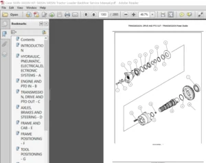
IMAGES PREVIEW OF THE MANUAL:
DESCRIPTION:
Case Vibratory Roller DV207 DV207HF Service Manual
FOREWORD:
This service manual is divided into several chapters. It includes technical and assembly data, adjustment guidelines and instructions in the use of special tools, jigs and aids. The primary purpose of this Service Manual is to provide basic information on removal, installation and servicing/ repair of the machine’s main groups. Machine group identifi cation in this manual corresponds to the Spare Parts Catalog.
- Before beginning work, we recommend that you mark any removed parts that will be reinstalled and that you cover all holes in individual hydraulic system parts to prevent hydraulic circuit contamination. When installing individual parts in the machine, tighten individual bolts or nuts as indicated in the torque tables (appendix) unless otherwise indicated in the text.
- ALWAYS observe the safety instructions and precautions indicated in Chapter 2. The manufacturer is continually improving the products based on operational experience and the latest knowledge. Consequently, the manufacturer reserves the right to make changes to the illustrations, descriptions, procedures or design patterns given in this manual as developments are made.
TABLE OF CONTENTS:
Case Vibratory Roller DV207 DV207HF Service Manual
1 Introduction 1-1
2 Safety precautions 2-1
21 Safety section 2-2
211 Precautionary statements – personal safety signal words 2-2
212 Machine safety and information signal words 2-2
213 General safety rules 2-3
214 General operating safety 2-4
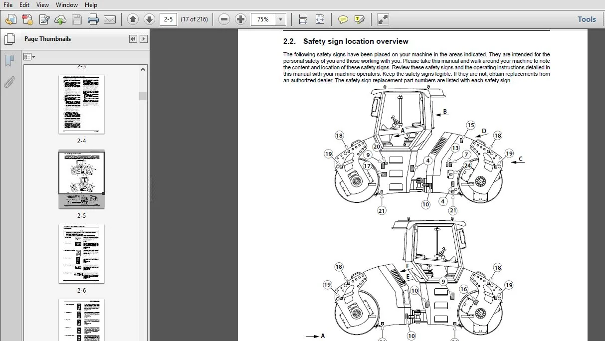
22 Safety sign location overview 2-5
221 Safety signs 2-6
23 General maintenance safety 2-10
231 Fire and explosion prevention 2-10
232 Hazardous chemicals 2-11
233 Battery safety 2-11
234 Air conditioning system 2-12
235 Transportation safety 2-12
236 Proper entry and exit 2-12
237 Operator presence system 2-12
238 Operator protective structure 2-13
239 Utility safety 2-13
24 Hand signals 2-14
3 Repair safety precautions 3-1
31 Safety regulations 3-2
32 Ecological measures & hygiene principles 3-6
33 Fire measures 3-7
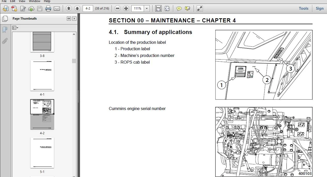
4 Product identifi cation 4-1
41 Summary of applications 4-2
5 Check the tightening of bolted joints 5-1
51 Check the tightening of bolted joints 5-2
SECTION 00 – MAINTENANCE
GENERAL SPECIFICATIONS
6 Description of the machine 6-1
61 Machine construction 6-2
62 Fluid/lubricant specifi cations 6-3
621 Engine oil 6-3
622 Fuel 6-4
623 Coolant 6-5
624 Hydraulic oil 6-5
625 Lube grease 6-5
626 Washer fl uid 6-5
627 Gear oil 6-5
628 Drum cooling liquid DV207HF 6-6
63 Technical data DV207 / DV207HF 6-7
64 Dimensional diagram DV207 / DV207HF 6-9
2 DV207 / DV207HF
TABLE OF CONTENTS
7 Tooling 7-1
71 Tooling and equipment 7-2
SECTION 10 – ENGINE
8 Removing the engine 8-1
9 Removing the cooler 9-1
SECTION 35 – HYDRAULIC SYSTEM
10 Hydraulic system 10-1
101 Hydraulic diagram 10-3
11 Hydraulics 11-1
111 Removing the cooling hydromotor 11-4
112 Removing the gear pump for steering 11-8
113 Removing the tandem pumps for vibration and travel 11-14
1131 Vibration pump 11-14
1132 Travel pump 11-16
114 Adjusting vibration frequency 11-18
115 Adjusting pulse sensors 11-19
116 Measuring hydraulic circuit safety pressures 11-20
SECTION 39 – FRAMES
12 Articulated joint 12-1
121 Preparation work 12-4
122 Removing the steering joint 12-10
123 Removing the slewing ring bearing 12-15
124 Removing the steering joint bearing 12-16
125 Installing the steering joint bearing 12-19
126 Adjusting the zero position of the steering joint 12-22
13 Removing the hood 13-1
SECTION 41 – STEERING
14 Steering cylinder 14-1
141 Removing hydraulic cylinders for steering and CRAB 14-4
142 Replacing packing material for steering or Crab hydraulic cylinders 14-5
SECTION 44 – AXLES AND WHEELS
15 Removing the drum 15-1
151 Removing the vibration hydromotor 15-12
152 Removing the travel hydromotor 15-14
153 Removing the auxiliary transmission 15-16
154 Removing the front drum 15-18
155 Replacing the rubber mounting of the drum 15-30
SECTION 50 – CAB CLIMATE CONTROL
16 Removing the heater/cooling air fans 16-1
161 Removing the heater 16-4
162 Removing cooling air fans 16-8
DV207 / DV207HF 3
TABLE OF CONTENTS
SECTION 55 – ELECTRICAL SYSTEM
17 Electrical installation 17-1
171 Fuses 17-2
172 Storage battery 17-4
173 Alternator 17-5
174 Starter Motor 17-7
175 Layout of wiring elements in the machine 17-10
18 Electrical system 18-1
181 Wiring diagram DV207 / DV207HF 18-3
SECTION 90 – CAB
19 Cab 19-1
191 Idle and parking brake position sensor 19-4
192 Left-hand control panel, reversing horn sensor 19-4
193 Seat platform 19-8
194 Power steering servo 19-12
195 Seat switch 19-16
INDEX
PLEASE NOTE:
- This is the same manual used by the DEALERSHIPS to SERVICE your vehicle.
- The manual can be all yours – Once payment is complete, you will be taken to the download page from where you can download the manual. All in 2-5 minutes time!!
- Need any other service / repair / parts manual, please feel free to contact us at heydownloadss @gmail.com . We may surprise you with a nice offer

Shane Tadeo –