Case Vibratory Roller SV212 and SV216 Service Manual 7-29530 – PDF DOWNLOAD
Original price was: $45.95.$25.95Current price is: $25.95.
Case Vibratory Roller SV212 and SV216 Service Manual
Part No: 7-29530
Description
Case Vibratory Roller SV212 and SV216 Service Manual
FILE DETAILS:
Case Vibratory Roller SV212 and SV216 Service Manual
Size : 62.7 MB
Format : PDF
Language : English
Brand: Case
Number of page: 240 page
Type of machine: Case Vibratory Roller
Type of document: Service Manual
Model: Case Vibratory Roller SV212 SV216
Part No: 7-29530
CASE VIBRATORY ROLLER SV212 AND SV216 SERVICE MANUAL 7-29530 – PDF DOWNLOAD:
IMAGES PREVIEW OF THE MANUAL:
DESCRIPTION:
Case Vibratory Roller SV212 and SV216 Service Manual
GENERAL SAFETY INSTRUCTIONS:
The following safety instructions must be observed by ALL repairing the machine.
1. Repairs may be carried out by skilled, trained and experienced personnel only.
2. When performing repairs, always use our shop manual. Special instructions for the assembly work are given in individual chapters of the manual.
3. Before putting the machine into operation acquaint yourselves with the machine controls as explained in the “Operator’s Manual” and make sure that you are perfectly familiar with the machine.
4. Do not use the machine if you do not fully understand all controls and until you know how the machine works.
5. Familiarize yourself with the area where you will work.
6. Do not carry out any redesign work or modifications on the machine because you could compromise the safety of the equipment.
7. Original parts and accessories have been designed especially for this machine.
8. Installation and use of spare parts not supplied by the manufacturer of the machine or not authorized by him can have negative effects on operational characteristics and safe operation of the machine.
REPAIRING AND INSPECTING THE MACHINE:
1. Wear working clothes and boots.
2. Use gloves when handling oils, fuel or coolant.
3. Protect your eyes with goggles or a shield when handling the battery.
4. Place the equipment on a flat and firm surface before starting repair. Secure the machine to prevent spontaneous movement.
5. Secure the frame of the machine and the drum to prevent rotation using a locking pin and a draw bar.
6. Before starting work remove the ignition key, disconnect the batteries and let hot parts cool down.
7. Attach a “Do not operate” warning note to the steering wheel and leave it there for the duration of the service work.
8. Wash the equipment thoroughly. If you use steam, do not expose electrical components and insulation directly to the steam, or otherwise cover them beforehand.
9. Keep all parts absolutely clean when dismantling, mounting, and servicing each assembly. Protect removed parts from getting soiled.
10. Clean the surface of dismantled parts and do the necessary to ensure adequately dust-free working conditions and a suitable storage area.
11. Be careful when handling cleaning agents. Do not use petrol or other easy inflammable materials for cleaning.
12. Dry the cleaned parts and immediately cover with anti corrosive protective oil- never install corroded parts.
13. Tools, hoists, safety equipment on chains, and other additional items must be serviceable and in good condition.
14. Use hoists and fasteners (ropes, chains) that have sufficient lifting capacity and are in good condition.
15. Make sure that there is enough fresh air supply when starting up the equipment in an enclosed area.
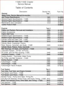
TABLE OF CONTENTS:
Case Vibratory Roller SV212 and SV216 Service Manual
SECTION 00 – MAINTENANCE
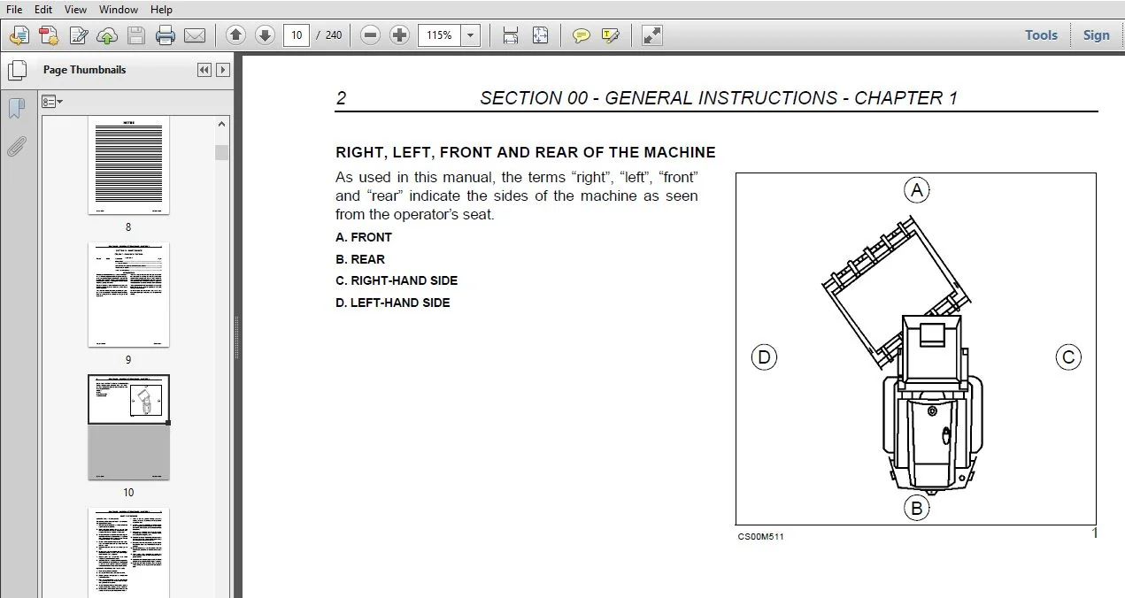
CHAPTER 1 – General Instructions
Description Page
Introduction 1
Safety instructions 3
Environmental measures and health precautions 6
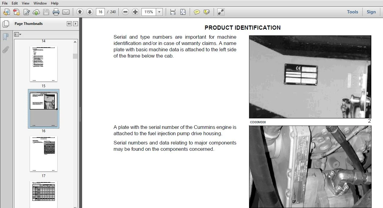
Product identification 8
Torque specifications 9
CHAPTER 2 – General Specifications
Description Page
Description of the machine 1
Fluids and lubricants 2
Specifications 5
Overall machine dimensions 9
CHAPTER 3 – Troubleshooting
Description Page
Troubleshooting – Engine 2
Troubleshooting – Hydraulic system oil overheating – emulsifying 3
Troubleshooting – Vibration 3
Troubleshooting – Travel 5
Troubleshooting – Brakes 6
Troubleshooting – Steering 6
SECTION 10 – ENGINE
CHAPTER 1 – Removal and installation
Description Page
Specifications 1
Description 2
Torque specifications 4
Special tools 4
Removal 6
Installation 13
Accelerator cable assembly removal and installation 13
2 CONTENTS
SV212 – SV216 7-29530 – 04-2001
SECTION 21 – TRANSMISSION
CHAPTER 1 – Hydraulic motor
Description Page
Description 2
Specifications 3
Torque specifications 3
Disassembly 3
Reconditioning and replacement 5
Assembly 8
CHAPTER 2 – Travel reduction gear
Description Page
Specification 1
Torque specifications 2
Special tools 2
Exploded view of travel brake 6
Disassembly and assembly 7
Brake test 9
Exploded view 10
Disassembly and assembly 11
SECTION 29 – HYDROSTATIC DRIVE
CHAPTER 1 – Pumps – Cento drive coupling
Description Page
Specifications 1
Tightening torque 1
Description 2
Special tools 3
Removal of pumps, Cento clutch 3
Cento drive coupling 7
SECTION 35 – HYDRAULIC SYSTEM
CHAPTER 1 – Hydraulic cylinders
Description Page
Torque Specifications 1
Description 2
Special tools 3
Hood hydraulic cylinders 5
Cab hydraulic cylinder 7
Hydraulic cylinders 7
7-29530 – 04-2001 SV212 – SV216
3 CONTENTS
CHAPTER 2 – Vibration Motor
Description Page
Description 2
Specifications 3
Torque specifications 3
Disassembly 3
Assembly 9
Supply pressure relief valve adjustment 13
CHAPTER 3 – Hydraulic circuit
Description Page
Hydraulic installation 2
Functional description 2
Travel without activation 3
Travel activated, moving forward 4
The multi-function valve 5
The idler-wheel lock-block on the flow divider 6
ASC valve 7
Vibration hydraulics 8
Vibration without activation 8
Vibration activated 9
Steering hydraulics 10
Steering without activation 11
Steering to the right 12
Lifting hydraulics 13
Lifting of the cab or hood 14
Lowering the cab and hood 15
Reservoir hydraulics 16
Hydraulic reservoir 16
Discharging of closed circuits 17
Brake release – emergency towing 18
Test points 19
Releasing transmission and wheel hydraulic motor brakes 20
Hydraulic diagram 22
CHAPTER 4 – Hydraulic pump
Description Page
Specifications 1
Torque specifications 1
Description 2
Disassembly 3
Reconditioning and replacement of parts 8
Assembly 14
Inspection and adjustments 26
4 CONTENTS
SV212 – SV216 7-29530 – 04-2001
SECTION 39 – FRAMES
CHAPTER 1 – Drum
Description Page
Description 2
Specifications 4
Torque specifications 4
Special tools 4
Drum removal 7
Vibrator plate assembly 14
Removal of the right side of the drum 16
Inspection and adjustment of vibration frequency 19
CHAPTER 2 – Articulation
Description Page
Specifications 1
Torque specifications 1
Description 2
Special tools 3
Disassembly 4
CHAPTER 3 – Drum Segments and Scrapers
Description Page
Specifications 1
Hardware torque 1
Special tools 1
Description 2
Segment installation 3
SECTION 41 – STEERING
CHAPTER 1 – Control
Description Page
Specifications 1
Special tools 1
Description 2
Fault finding – steering 3
Disassembly and assembly of steering wheel 3
CHAPTER 2 – Steering cylinders
Description Page
Specifications 1
Special torques 1
Special tools 2
Removal of steering cylinders 3
Replacing the seals 4
7-29530 – 04-2001 SV212 – SV216
5 CONTENTS
CHAPTER 3 – Steering control valve
Description Page
Specifications 1
Tightening torques 1
Description 2
Special tools 3
Disassembly 4
Reassembly 7
Functional check 12
SECTION 50 – HEATER – AIRCONDITIONING
CHAPTER 1 – Removal and installation
Description Page
Specifications 1
Removal 2
Defects in the airconditioning system 4
Replacing (tightening) the belt 5
SECTION 55 – ELECTRICAL CIRCUIT
CHAPTER 1 – Wiring diagram
Description Page
Electrical installation 1
SECTION 90 – PLATFORM, CAB
CHAPTER 1 – Operator’s compartment
Description Page
Torque specifications 1
Operator’s compartment 2
Travel brake control adjustment
PLEASE NOTE:
- This is the SAME manual used by the dealers to troubleshoot any faults in your vehicle. This can be yours in 2 minutes after the payment is made.
- Contact us at [email protected] should you have any queries before your purchase or that you need any other service / repair / parts operators manual.
Kole Kevin –
The manuals I have purchased are very good. I am very pleased.