Cat 300C 400C 402 Hydra-Trac Self Contained Hydraulic Track Drill Service Manual – PDF DOWNLOAD
Original price was: $98.95.$38.95Current price is: $38.95.
Cat 300C 400C 402 Hydra-Trac Self Contained Hydraulic Track Drill Service Manual – PDF DOWNLOAD
Part No. 0409147
Description
Cat 300C 400C 402 Hydra-Trac Self Contained Hydraulic Track Drill Service Manual – PDF DOWNLOAD
CAT 300C 400C 402 HYDRA-TRAC SELF CONTAINED HYDRAULIC TRACK DRILL SERVICE MANUAL – PDF DOWNLOAD:
IMAGES PREVIEW OF THE MANUAL:


DESCRIPTION:
Cat 300C 400C 402 Hydra-Trac Self Contained Hydraulic Track Drill Service Manual – PDF DOWNLOAD
Parts Ordering and Product Support :
Use only genuine Reedrill parts in the maintenance, rebuild, or repair, of Reedrill machines. Reedrill shall have no liability as to any unauthorized modification of machines or parts and shall have no obligation or liability as to any machines or parts which have been improperly handled, or which have not been operated, maintained, or repaired according to Reedrill’s furnished manuals, or other written instructions, or which are operated with other than genuine Reedrill parts.
1. IDENTIFICATION OF THE MACHINE
Always furnish the Reedrill Model Number and Serial Number when ordering parts. This information is found on the machine nameplate. Rock Drills have the serial number stamped on the cylinder.
2. PART NUMBER AND DESCRIPTION
In addition to the Serial Number, always give the part number and description of each part ordered. If there is any doubt as to the correct part number and description, furnish a dimensioned sketch or return the part to be replaced, transportation charges prepaid.
3. SHIPMENT
Unless otherwise instructed, all shipments will be made via motor freight collect or UPS prepaid and charged on our invoice. Shipments cannot be made on open account until your credit has been approved by our Accounting Department.
Part No. 0409147
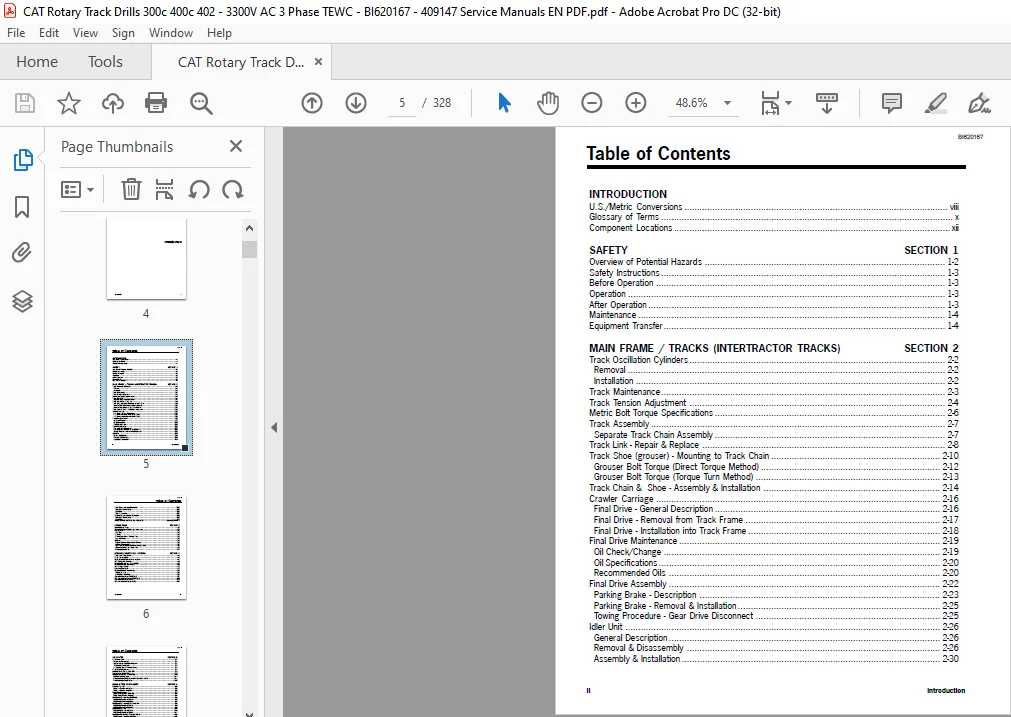
TABLE OF CONTENTS:
Cat 300C 400C 402 Hydra-Trac Self Contained Hydraulic Track Drill Service Manual – PDF DOWNLOAD
INTRODUCTION
US/Metric Conversions viii
Glossary of Terms x
Component Locations xii
SAFETY SECTION 1
Overview of Potential Hazards 1-2
Safety Instructions 1-3
Before Operation 1-3
Operation 1-3
After Operation 1-3
Maintenance 1-4
Equipment Transfer 1-4
MAIN FRAME / TRACKS (INTERTRACTOR TRACKS) SECTION 2
Track Oscillation Cylinders 2-2
Removal 2-2
Installation 2-2
Track Maintenance 2-3
Track Tension Adjustment 2-4
Metric Bolt Torque Specifications 2-6
Track Assembly 2-7
Separate Track Chain Assembly 2-7
Track Link – Repair & Replace 2-8
Track Shoe (grouser) – Mounting to Track Chain 2-10
Grouser Bolt Torque (Direct Torque Method) 2-12
Grouser Bolt Torque (Torque Turn Method) 2-13
Track Chain & Shoe – Assembly & Installation 2-14
Crawler Carriage 2-16
Final Drive – General Description 2-16
Final Drive – Removal from Track Frame 2-17
Final Drive – Installation into Track Frame 2-18
Final Drive Maintenance 2-19
Oil Check/Change 2-19
Oil Specifications 2-20
Recommended Oils 2-20
Final Drive Assembly 2-22
Parking Brake – Description 2-23
Parking Brake – Removal & Installation 2-25
Towing Procedure – Gear Drive Disconnect 2-25
Idler Unit 2-26
General Description 2-26
Removal & Disassembly 2-26
Assembly & Installation 2-30
BI620167
Introduction iii
Table of Contents
Track Rollers – General Description 2-33
Removal & Disassembly 2-34
Assembly 2-36
Test & Installation 2-37
Support Rollers – General Description 2-38
Removal & Disassembly 2-39
Assembly 2-41
Caterpillar Track Assembly (early machines) alternate Section 2
POWER TRAIN SECTION 3
Main Hydraulic Pump 3-2
Hydraulic Pumps – Removal and Installation 3-2
Fuel System 3-3
Fuel Tank 3-3
Priming 3-4
Priming with Manual Priming Pump 3-5
Fuel Inlet Screen 3-5
Coolers 3-6
Engine Radiator – Capacity and Service 3-6
Coolant Specifications 3-7
Fan Guard Assembly – Removal and Installation 3-9
Coolers – Removal and Installation 3-9
Changing Hydraulic Oil 3-11
HYDRAULIC/ELECTRICAL SYSTEMS SECTION 4
Tram Valve Components 4-2
Valve Tray Assembly 4-4
Basic Hydraulic Schematic – all models 4-7
Cab Piping – Drill Control 4-8
Boom and Feed Piping – 300C/400C 4-9
Boom and Feed Piping – 402C 4-10
Rod Changer Piping 4-11
Electrical Schematic 4-11
Hydraulic Valves – Maintenance 4-14
Tram Pilot Valve 4-14
Boom/Feed Pilot Valve 4-15
Electrical Schematic – 300C/400C 4-17
Cab Electrical Schematic – 300C/400C 4-20
Electrical Schematic – 402C 4-23
Cab Electrical Schematic – 402C 4-24
BI620167
iv Introduction
Table of Contents
AIR SYSTEM SECTION 5
Air Receiver Tank 5-2
Preventive Maintenance 5-2
Compressor Oil Separator Element: 5-2
Preventive Maintenance 5-2
Air Receiver Tank – Troubleshooting 5-4
Air System Components 5-7
Compressor Oil Piping – 300 CFM 5-8
Thermostatic Bypass Valve 5-8
Compressor Assembly – 300 CFM 5-10
Removal and Installation 5-11
Drive Coupling – Replacement of Rubber Drive Blocks 5-11
Drive Coupling – Replacement 5-12
BOOM & FEED COMPONENTS SECTION 6
Boom Lift Cylinder 6-2
Boom Lift Cylinder – Removal 6-2
Boom Lift Cylinder – Replace 6-3
Boom Swing Cylinder 6-4
Boom Swing Cylinder – Removal 6-4
Boom Swing Cylinder – Replace 6-4
Feed Dump Cylinder – Standard Boom 6-6
Feed Dump Cylinder – Removal 6-6
Feed Dump Cylinder – Replace 6-7
Feed Dump Cylinder – Heavy Duty Boom 6-8
Feed Dump Cylinder – Removal 6-8
Feed Dump Cylinder – Replace 6-9
Feed Swing Cylinder 6-10
Feed Swing Cylinder – Removal 6-10
Feed Swing Cylinder – Replace 6-11
Feed Extension Cylinder – Standard Boom 6-12
Feed Extension Cylinder – Removal 6-12
Feed Extension Cylinder – Replace 6-13
Feed Extension Cylinder – Heavy Duty Boom 6-14
Feed Extension Cylinder – Removal 6-14
Feed Extension Cylinder – Replace 6-15
Standard Boom Shim/Wear Pad Replacement 6-16
Standard Boom – Inspection 6-17
Feed and Inner Boom Tube – Removal 6-18
Boom Tube, Wear Pad & Shims Installation 6-22
Feed Installation 6-23
Heavy Duty Boom Shim/Wear Pad Replacement 6-24
Heavy Duty Boom – Inspection 6-25
Feed and Inner Boom Tube – Removal 6-26
Boom Tube, Wear Pad & Shims Installation 6-29
BI620167
Introduction v
Table of Contents
Feed Installation 6-31
Hydraulic Rock Drill – HPR1H-AT 6-32
Removal from Feed 6-33
Installation on Feed 6-33
Hydraulic Rock Drill – HPR2 6-34
Removal from Feed 6-35
Installation on Feed 6-35
Feed Chain/Mounting Slide Adjustment 6-36
Feed Chain Tension – Offset Feed 6-37
Feed Chain Tension – Inline Feed 6-37
Adjustment 6-37
PRESSURE SETTINGS & ADJUSTMENTS SECTION 7
Engine Adjustments 7-2
Engine Low & High Idle 7-2
Cooler Fan Adjustments 7-3
Brake Valve Adjustments 7-4
Tram Valve Adjustments 7-6
Joystick Adjustments 7-7
Main Pump Adjustments – Early Models w/o Relief Valve – Rexroth 160 7-12
Main Pump Adjustments – Early Models with Relief Valve – Rexroth 160 7-14
Clipping Relief Valve Setting – Early Models w/o Main Pump Relief Valve 7-16
Main Pump Adjustments – Late Models – Rexroth 190 7-18
Rotation Pump Adjustments – Early Models – Vickers PVE21 7-20
Case Drain 7-21
Rotation Pump Adjustments – Late Models – Commercial Intertech & Rexroth 7-22
Case Drain 7-23
Drill Valve Adjustments 7-24
Drill (Hammer), Rotation, Feed & Feed Override Valves 7-25
Collaring Circuit Adjustment 7-26
Anti-Jam Circuit Adjustment 7-28
Air Compressor Speed and Motor Adjustment 7-32
Detergent Pump and System (Optional) – Adjustment 7-34
Detergent System Piping (pump with non-pressurized tank) 7-35
Dust Collector Assembly 7-37
Function of Dust Collector 7-37
Detailed Function of Components 7-37
Initial Start-up and Tuning (300C/400C machines) 7-38
Set Dust Collector Valve 7-38
Set Timer 7-39
Set Fan Speed 7-39
Initial Start-up and Tuning (402C machines) 7-40
Set Dust Collector Valve 7-41
Set Timer 7-41
Set Fan Speed 7-41
BI620167
vi Introduction
Table of Contents
Operational Variables 7-42
Fine Tuning 7-42
Manometer Setup Instructions 7-45
Timer Installation 7-46
Control Circuit 7-47
Fan Removal and Installation 7-48
Troubleshooting Hints 7-49
Centralizer Adjustment 7-51
Vertical Indicator (Optional) – Adjustment, Wiring & Troubleshooting 7-52, 53
Cold Weather Start Package 7-55
Rod Changer Valve Adjustment 7-56
VENDOR SERVICE INFORMATION SECTION 8
See separate listing at the beginning of section 8
HYDRAULIC ROCK DRILL REPAIR SECTION 9
HPR1H Hydraulic Rock Drill Service Manual (part no 1418808)
or
HPR2 Hydraulic Rock Drill Service Manual (part no 0408860)
LUBRICATION AND TORQUE SPECIFICATIONS SECTION 10
Hydraulic Oils for Percussion Drills 10-2
Lubrication and Inspection 10-3
Bolt Maintenance 10-3
Maintenance Schedule 10-4
Daily Operational Checklist 10-5
Bolt Torque Specifications 10-6
PLEASE NOTE:
- This is not a physical manual but a digital manual – meaning no physical copy will be couriered to you. The manual can be yours in the next 2 mins as once you make the payment, you will be directed to the download page IMMEDIATELY.
- This is the same manual used by the dealers inorder to diagnose your vehicle of its faults.
- Require some other service manual or have any queries: please WRITE to us at [email protected]
S.V