Cat 3406E On-Highway Engine Disassembly & Assembly Manual – PDF DOWNLOAD
Original price was: $89.95.$19.95Current price is: $19.95.
Cat 3406E On-Highway Engine Disassembly & Assembly Manual – PDF DOWNLOAD
1MM1-Up (Engine)
2WS1-Up (Engine)
Description
Cat 3406E On-Highway Engine Disassembly & Assembly Manual – PDF DOWNLOAD
FILE DETAILS:
Cat 3406E On-Highway Engine Disassembly & Assembly Manual – PDF DOWNLOAD
Language : English
Pages : 137
Downloadable : Yes
File Type : PDF
Size: 31.7 MB
IMAGES PREVIEW OF THE MANUAL:


TABLE OF CONTENTS:
Cat 3406E On-Highway Engine Disassembly & Assembly Manual – PDF DOWNLOAD
1MM1-Up (Engine)
2WS1-Up (Engine)
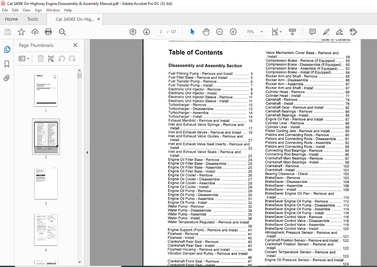
Disassembly and Assembly Section
Fuel Priming Pump – Remove and Install 5
Fuel Filter Base – Remove and Install 5
Fuel Transfer Pump – Remove 6
Fuel Transfer Pump – Install 7
Electronic Unit Injector – Remove 8
Electronic Unit Injector – Install 9
Electronic Unit Injector Sleeve – Remove 11
Electronic Unit Injector Sleeve – Install 11
Turbocharger – Remove 12
Turbocharger – Disassemble 13
Turbocharger- Assemble 14
Turbocharger – Install 14
Exhaust Manifold – Remove and Install 15
Inlet and Exhaust Valve Springs – Remove and
Install 17
Inlet and Exhaust Valves – Remove and Install 19
Inlet and Exhaust Valve Guides – Remove and
Install 21
Inlet and Exhaust Valve Seat Inserts – Remove and
Install 22
Inlet and Exhaust Valve Seals – Remove and
Install 23
Engine Oil Filter Base – Remove 24
Engine Oil Filter Base – Disassemble 25
Engine Oil Filter Base – Assemble 25
Engine Oil Filter Base – Install 26
Engine Oil Cooler – Remove 26
Engine Oil Cooler – Disassemble 27
Engine Oil Cooler – Assemble 28
Engine Oil Cooler – Install 29
Engine Oil Pump – Remove 29
Engine Oil Pump – Disassemble 30
Engine Oil Pump – Assemble 31
Engine Oil Pump – Install 32
Water Pump – Remove 32
Water Pump – Disassemble 34
Water Pump – Assemble 35
Water Pump – Install 36
Water Temperature Regulator – Remove and Install
38
Engine Support (Front) – Remove and Install 41
Flywheel – Remove 41
Flywheel – Install 42
Crankshaft Rear Seal – Remove 43
Crankshaft Rear Seal – Install 43
Flywheel Housing – Remove and Install 44
Vibration Damper and Pulley – Remove and Install
46
Crankshaft Front Seal – Remove 47
Crankshaft Front Seal – Install 48
Front Cover – Remove 48
Front Cover – Install 49
Gear Group (Front) – Remove 49
Gear Group (Front) – Install 52
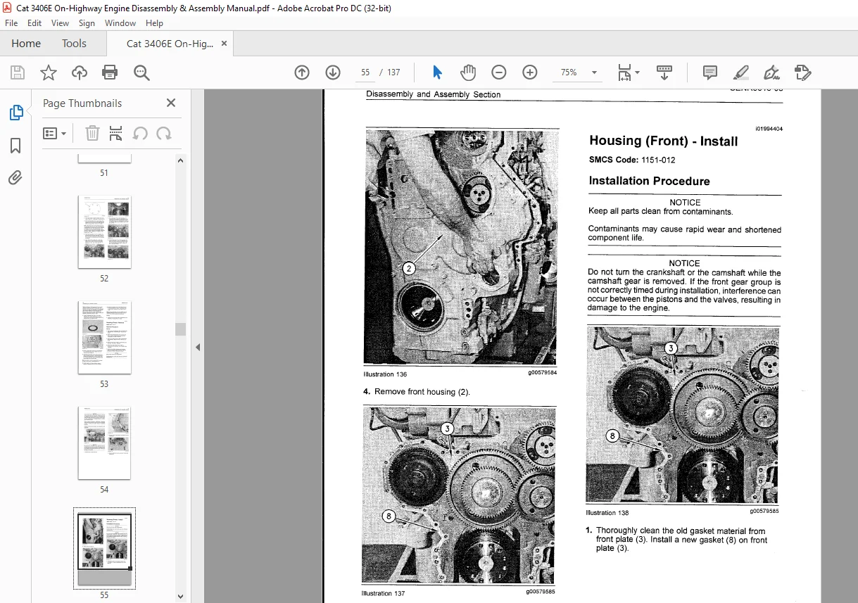
Housing (Front) – Remove 54
Housing (Front) – Install 56
Valve Mechanism Cover – Remove and Install 58
3
Table of Contents
Valve Mechanism Cover Base – Remove and
Install 58
Compression Brake – Remove (If Equipped) 60
Compress!on Brake – Disassemble (If Equipped) 60
Compress~on Brake – Assemble (If Equipped) 63
Compression Brake – Install (If Equipped) 64
Rocker Arm and Shaft – Remove 65
Rocker Arm – Disassemble 66
Rocker Arm – Assemble 67
Rocker Arm and Shaft – Install 67
Cylinder Head – Remove 68
Cylinder Head – Install 71
Camshaft – Remove 7 4
Camshaft – Install 78
Camshaft Gear – Remove and Install 82
Camshaft Bearings – Remove 84
Camshaft Bearings – Install 85
Engine Oil Pan – Remove and Install 87
Cylinder Liner – Remove 88
Cylinder Liner – Install 89
Piston Cooling Jets – Remove and Install 89
Pistons and Connecting Rods – Remove 90
Pistons and Connecting Rods – Disassemble 91
Pistons and Connecting Rods – Assemble 92
Pistons and Connecting Rods – Install 95
Connecting Rod Bearings – Remove 95
Connecting Rod Bearings – Install 96
Crankshaft Main Bearings – Remove 97
Crankshaft Main Bearings – Install 98
Crankshaft – Remove 100
Crankshaft- Install 101
Bearing Clearance – Check 102
BrakeSaver – Remove 103
BrakeSaver – Disassemble 104
BrakeSaver – Assemble 106
BrakeSaver- Install 109
BrakeSaver Engine Oil Pan – Remove and
Install 110
BrakeSaver Engine Oil Pump – Remove 112
BrakeSaver Engine Oil Pump – Disassemble 113
BrakeSaver Engine Oil Pump -Assemble 114
BrakeSaver Engine Oil Pump – Install 116
BrakeSaver Control Valve – Remove 116
BrakeSaver Control Valve – Disassemble 118
BrakeSaver Control Valve – Assemble 119
BrakeSaver Control Valve – Install 120
Atmospheric Pressure Sensor – Remove and
Install 121
Camshaft Position Sensor – Remove and Install 122
Crankshaft Position Sensor – Remove and
Install 122
Coolant Temperature Sensor – Remove and
Install 123
Engine Oil Pressure Sensor – Remove and Install
124
Fuel Temperature Sensor- Remove and Install 125
Boost Pressure Sensor – Remove and Install 125
Inlet Air Temperature Sensor – Remove and
Install 126
Fan Drive – Remove 127
Fan Drive – Disassemble 127
Fan Drive – Assemble 127
Fan Drive – Install 128
Table of Contents
Engine Control Module – Remove and Install 129
Electric Starting Motor – Remove and Install 130
Air Compressor – Remove and Install 130
Air Compressor Drive Gear – Remove 132
Air Compressor Drive Gear – Install (Two
Cylinder) 133
Air Compressor Drive Gear – Install 133
Index Section
Index 135
CAT 3406E ON-HIGHWAY ENGINE DISASSEMBLY & ASSEMBLY MANUAL – PDF DOWNLOAD:
PLEASE NOTE:
- This is the SAME MANUAL used by the dealerships to diagnose your vehicle
- No waiting for couriers / posts as this is a PDF manual and you can download it within 2 minutes time once you make the payment.
- Your payment is all safe and the delivery of the manual is INSTANT – You will be taken to the DOWNLOAD PAGE.
- So have no hesitations whatsoever and write to us about any queries you may have : heydownloadss @gmail.com
S.V