CAT 6020B Hydraulic Shovel Operation & Maintenance Manual DNR00101 – DNR00104 – PDF DOWNLOAD
$28.95
CAT 6020B Hydraulic Shovel Operation & Maintenance Manual DNR00101 – DNR00104 – PDF DOWNLOAD
Description
CAT 6020B Hydraulic Shovel Operation & Maintenance Manual DNR00101 – DNR00104 – PDF DOWNLOAD
FILE DETAILS:
CAT 6020B Hydraulic Shovel Operation & Maintenance Manual DNR00101 – DNR00104 – PDF DOWNLOAD
Language : English
Pages : 336
Downloadable : Yes
File Type : PDF
DESCRIPTION:
CAT 6020B Hydraulic Shovel Operation & Maintenance Manual DNR00101 – DNR00104 – PDF DOWNLOAD
PREFACE:
About this Operation and Mainte- nance Manual:
- This Operation and Maintenance Manual is de- signed to familiarize the operator with the
machine and its designated use. - The Operation and Maintenance Manual contain important information on how to operate the
ma- chine safely, properly and with maximum effi- ciency. Observing these instructions
helps to pre- vent hazardous situations, to reduce repair costs and downtimes and to
increase the reliability and service life of the machine. - The Operation and Maintenance Manual must be supplemented by the respective national rules
and regulations for accident prevention and environ- mental protection. - The Operation and Maintenance Manual must always be available in the operator’s cab
of the machine.
The Operation and Maintenance Manual must be read and put into practice by any person in
charge of carrying out work with or on the machine, such as
▪ operation, including setting-up, troubleshoot- ing in the course of work, care,
evacuation of production waste and disposal of fuels and consumables,
▪ maintenance (inspection, servicing, repair) and / or
▪ transport.
- In addition to the Operation and Maintenance Man- ual and the mandatory rules and regulations
for accident prevention and environmental protection in the user’s country and at the
place where the machine is to be used, the generally recognized technical rules for
safe and proper working must be observed ¹. - The Operation and Maintenance Manual is di- rected to the mining-machine specialist. It
cannot provide basic know-how. This can be acquired, for example, in several days’ instruction by a
qualified Caterpillar Global Mining Hydraulic Mining Shovels GmbH (CGM HMS GmbH) mechanic or by
attend- ing an CGM HMS training course for operators or maintenance personnel. - The CGM HMS after-sales service will be pleased to deal with any queries you may have after read-
ing through the operating instructions. - All CGM HMS Operation and Maintenance Manu- als are issued in German and then translated.
Even a good translation may give rise to questions which CGM HMS will be pleased to answer. - The Operation and Maintenance Manual contain no work instructions for carrying out major
repairs. Such work is willingly done for you by the Caterpil-
lar dealer service.
IMAGES PREVIEW OF THE MANUAL:
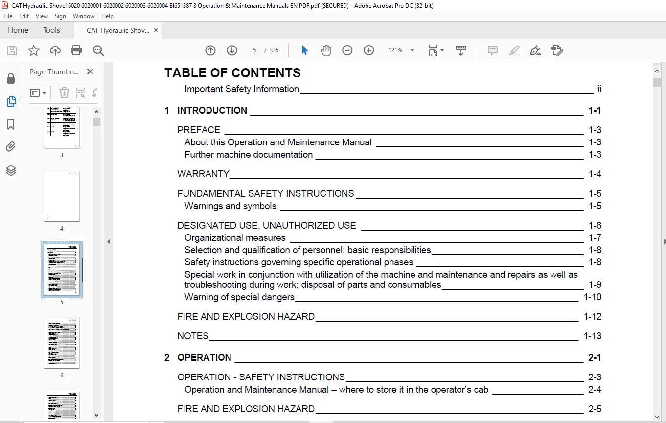
TABLE OF CONTENTS:
CAT 6020B Hydraulic Shovel Operation & Maintenance Manual DNR00101 – DNR00104 – PDF DOWNLOAD
1 INTRODUCTION 1-1
PREFACE 1-3
About this Operation and Maintenance Manual 1-3
Further machine documentation 1-3
WARRANTY 1-4
FUNDAMENTAL SAFETY INSTRUCTIONS 1-5
Warnings and symbols 1-5
DESIGNATED USE, UNAUTHORIZED USE 1-6
Organizational measures 1-7
Selection and qualification of personnel; basic responsibilities 1-8
Safety instructions governing specific operational phases 1-8
Special work in conjunction with utilization of the machine and maintenance and repairs as well as
troubleshooting during work; disposal of parts and consumables 1-9
Warning of special dangers 1-10
FIRE AND EXPLOSION HAZARD 1-12
NOTES 1-13
2 OPERATION 2-1
OPERATION – SAFETY INSTRUCTIONS 2-3
Operation and Maintenance Manual – where to store it in the operator’s cab 2-4
FIRE AND EXPLOSION HAZARD 2-5
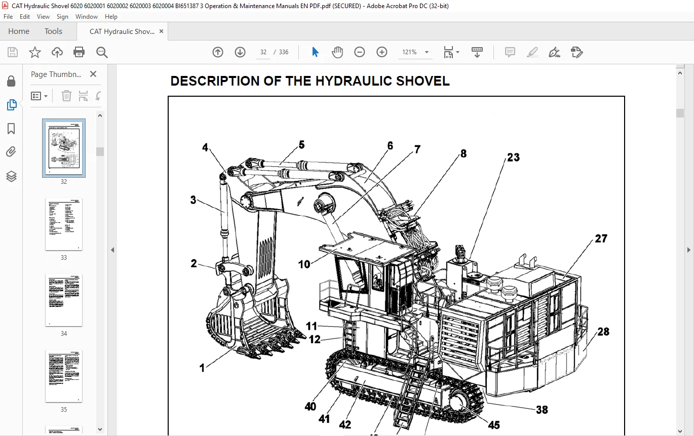
DESCRIPTION OF THE HYDRAULIC SHOVEL 2-6
Hydraulic shovel layout 2-7
Undercarriage 2-8
Upper structure 2-8
Power module 2-8
Hydraulic system 2-8
Control and Monitoring Platform (CAMP) 2-8
Board-Control-System (BCS) – information 2-9
Demand control / Zero-flow regulation 2-9
Automatic reset to idling 2-9
Electrical system 2-9
Safety films and warning messages – overview and description 2-10
Safety messages 2-16
Additional messages 2-23
Machine number plate – location 2-25
Component numbers – location 2-25
Engine number plate – location 2-25
Engine information plate – location 2-25
Entering and leaving the machine 2-26
Boarding ladder lighting – switching on / off 2-27
Hydraulic boarding ladder – raising / lowering 2-28
Operator’s cab – lock / unlock the door 2-29
BA 6020B(3 847 000.00)-EN
Table of contents
1-6
Operator’s cab – open the door from inside 2-29
Cab interior lights – switching on / off 2-30
Maintenance lights – switching on / off 2-31
Battery main switch – switching on / off 2-31
Emergency exit in operator’s cab and escape ladder 2-32
Emergency ladder on the righthand side of upper structure 2-33
Emergency lowering the boarding ladder from the ground 2-33
Emergency shut-off – function 2-34
Putting the machine back into operation – reset of emergency shut off function 2-35
Starter isolator switch – shutting off starter voltage 2-36
Battery isolator switch – shutting off supply voltage 2-36
Operator’s seat – adjustment 2-37
Operators exposure to vibrations – reducing 2-38
Operator’s seat belt – use 2-38
Trainer’s / instructor’s seat – use 2-39
Jump seat – use 2-39
Fire extinguisher – location 2-40
Windscreen wiper / washer – function 2-41
Windscreen washer nozzles– adjust 2-41
Windscreen washer reservoir – refill 2-42
Mirror– adjusting position 2-42
BCS display monitor – adjusting position 2-43
Operating hours meter – location 2-43
Power receptacle inside cab – use 2-44
Roller blinds – adjusting position 2-44
MONITORING, WARNING AND CONTROL ELEMENTS IN CAB 2-46
Engine, control and monitoring 2-51
MACHINE – PUTTING INTO OPERATION 2-62
Operator’s exposure to noise – reducing 2-62
Refuelling 2-63
Diesel fuel – recommendations 2-63
Diesel fuel tank – refilling 2-63
Refuelling using the Service Station 2-64
Electrical system – switching on and off 2-69
Engine – emergency shut-off 2-69
ENGINE – STARTING AND STOPPING 2-70
Engine – starting 2-70
Engine – adjusting the speed 2-71
Engine – starting at low temperatures 2-71
Engine – shutting off 2-72
HVAC – UNIT, FUNCTION 2-73
HVAC – unit, controls 2-74
MAXIMUM MACHINE INCLINATIONS – INFORMATION 2-76
TRAVELLING – SAFETY INSTRUCTIONS 2-78
TRAVELLING 2-79
Upper structure basic position 2-79
Travelling forwards/backwards 2-79
BA 6020B(3 847 000.00)-EN
Table of contents
1-7
Travelling speed – adjust 2-80
Travelling uphill and downhill 2-80
Cornering 2-81
Turning 2-81
Travelling over long distances 2-82
Travelling in water or mud 2-83
Upper structure holding brake – function 2-84
Track parking brake – function 2-84
TRANSPORTING THE MACHINE 2-85
Transport – Safety instructions 2-85
WORKING OPERATION – SAFETY INSTRUCTIONS 2-86
Hydraulic cylinders – running-in instructions 2-87
Hydraulic system – warming up 2-87
WORKING OPERATION 2-89
Before starting work 2-89
Pilot hydraulic circuit – activating 2-89
Upper structure – swinging 2-90
Working movements 2-91
WORKING TECHNIQUES 2-92
Restricted operation 2-92
Backhoe operation – digging and loading 2-93
Bench – climbing and leaving 2-94
Emergency lowering of the working equipment 2-95
After daily operation 2-95
OPTIONAL EQUIPMENT 2-96
Additional silencers – function 2-96
Rotary beacon – switching on / off 2-96
ASSEMBLING WORKING EQUIPMENT – SAFETY INSTRUCTIONS 2-97
Securing the machine 2-98
CORROSION PROTECTION FOR PINS AND BEARINGS (BUSHINGS AND HUBS) 2-99
NOTES 2-101
3 INSPECTION AND SERVICING 3-1
INSPECTION AND SERVICING – SAFETY INSTRUCTIONS 3-3
INSPECTION AND SERVICING WORK, FIRE AND EXPLOSION HAZARD 3-7
INSPECTION AND SERVICING PLANS – INSTRUCTIONS 3-9
Plan V 3-11
Plan N 3-13
Plan T and W 3-15
Plan A – E 3-17
LUBRICATING CHART – GREASE 3-24
Lubricating chart – Grease (legend) 3-25
Filling quantities – Grease 3-25
BA 6020B(3 847 000.00)-EN
Table of contents
1-8
LUBRICATING CHART – GREASE, WORKING EQUIPMENT 3-26
Lubricating chart – Grease, working equipment (legend) 3-27
INSPECTION PLAN – OIL 3-28
Inspection plan – Oil (legend) 3-29
Filling quantities – oil 3-30
Filling quantities – other 3-30
LUBRICANTS / CONSUMABLES 3-31
Notes on the selection of oils and greases 3-31
Avoid mixing of different hydraulic fluids 3-31
I. Oils for combustion engines 3-32
II. Fluid for hydraulic system 3-33
III Oils for pump drive gearboxes, swing gearboxes and travel gearboxes 3-34
V. Grease for bearings and swing rings (Central lubrication system) 3-35
Grease for idlers, track rollers and support rollers (Lifetime lubrication) 3-36
Coolant for use on all combustion engines 3-37
SERVICING WORK 3-38
Maintenance access – doors and cover locations 3-38
ENGINE 3-39
Engine – Safety instructions 3-39
Engine oil level – Checking / Topping up 3-40
Engine oil – Changing 3-41
Engine oil filters – Replacing 3-43
Cold-starting fluid (ether) – Replacing the pressure vessel 3-44
Cold-starting fluid (ether) – Replacing the pressure vessel 3-44
ENGINE COOLING SYSTEM – INFORMATION 3-45
Radiator core – clean 3-46
Cooling-liquid – Checking level 3-46
Cooling liquid – change 3-49
Cooling liquid – Testing the composition 3-51
Engine bearings – inspect 3-51
Engine crankcase breather – clean 3-52
AIR-INTAKE SYSTEM – INFORMATION 3-53
Dust trap – Cleaning 3-53
Primary filter elements – Check, clean, replace 3-54
Secondary filter element – replace 3-56
Clean-air lines and hoses – inspect 3-56
FUEL SYSTEM 3-57
Fuel system – Safety instructions 3-57
Fuel filter – information 3-57
Fuel tank supply valve – function 3-58
Fuel filter – drain water 3-58
Fuel filter – replace 3-59
Fuel system – venting 3-60
Fuel tank breather filter – replace 3-61
Fuel tank – cleaning 3-62
Fuel tank – drain water and sediment 3-63
Water trap (optional) – check 3-64
BA 6020B(3 847 000.00)-EN
Table of contents
1-9
ELECTRICAL SYSTEM 3-66
Electrical system – Safety instructions 3-66
Alternator – Instructions 3-66
Electrical circuit diagrams 3-66
Electrical system switch-cabinets 3-66
Fuses – information 3-66
Lamps and bulbs – replace 3-66
Charging batteries inside the machine – safety instructions 3-67
Battery – maintenance 3-68
Battery – removing and installing 3-69
Equipotential bonding – inspect 3-70
Lighting systems in LED technonogy – instructions 3-72
HYDRAULIC SYSTEM 3-73
Hydraulic system – Safety instructions 3-73
Hydraulic system – depressurize 3-73
Hydraulic oil level – check 3-74
Hydraulic oil return-flow filters (hydraulic oil reservoir) – replace 3-76
Hydraulic oil return-flow filters (filter housing) – replace 3-78
Bypass valves (hydraulic oil tank) – clean / replace 3-79
Hydraulic tank angled screens – inspect 3-80
Hydraulic tank breather filter – replace 3-80
Filter (pilot hydraulic circuit) – replace 3-81
High-pressure filter for working hydraulics – replace 3-82
Hydraulic oil – change 3-83
Avoid mixing of different hydraulic fluids 3-83
Hydraulic system – venting 3-87
Hydraulic oil cooler – clean 3-88
Pressure accumulator – emergency lowering and pilot circuit 3-89
PUMP DRIVE GEARBOX P/N 3855122 3-90
Pump drive gearbox – checking the oil level / Topping up with oil 3-90
Pump drive gearbox – change oil 3-91
Pump drive gearbox breather – replace 3-92
PUMP DRIVE GEARBOX P/N 3855121 3-93
Pump drive gearbox – checking the oil level / Topping up with oil 3-93
Pump drive gearbox – change oil 3-94
Pump drive gearbox breather – replace 3-95
Pump drive gearbox oil filter – replace 3-96
SWING GEARBOX P/N 3857027 3-97
Swing gearbox – checking the oil level / Topping up with oil 3-97
Swing gearbox – change oil 3-98
Swing gearbox breather – replace 3-99
TRAVEL GEARBOX 3-100
Travel gearbox main stage – Checking the oil level / Topping up with oil 3-100
Travel gearbox pre-stage – Checking the oil level / Topping up with oil 3-101
Travel gearbox brake housing – Checking the oil level / Topping up with oil 3-101
Travel motor coupling housing – Checking the oil level / Topping up with oil 3-102
Travel gearbox main stage – Changing oil 3-102
Travel gearbox pre-stage – Changing oil 3-103
Travel motor coupling housing – Changing oil 3-103
BA 6020B(3 847 000.00)-EN
Table of contents
1-10
Travel gearbox brake housing – Changing oil 3-104
Travel gearbox breather – replace 3-104
CRAWLER TRACKS 3-105
Tracks – Cleaning 3-105
Track roller, Support roller – Check tightening of bolts 3-106
Track tensioner – Checking 3-107
Pressure accumulator – track tensioner 3-108
SWING RING 3-109
Swing ring – Instructions 3-109
Swing ring – Checking the grease filling Swing ring – Checking the grease filling 3-110
CENTRAL LUBRICATING SYSTEM 3-111
Central lubricating system – function 3-111
Grease drum – replace 3-113
Grease pump – checking hydraulic pressure 3-114
Grease lines – checking greasing pressure 3-115
Grease drum breather – replace 3-116
Grease drum – check filling level 3-116
Grease filter – check / clean 3-117
Grease pump – checking oil level 3-118
Grease pump – changing oil 3-118
OTHER MAINTENANCE 3-119
Engine – other maintenance 3-119
HVAC, filter elements fresh air (outside) – replace 3-120
HVAC, filter element inside cab – check / clean 3-121
Additional silencers – check / clean 3-121
Excavator controls – clean, lubricate 3-122
Window panes – cleaning 3-123
Floor window pane – cleaning 3-123
Seat belt – inspect 3-124
PUTTING THE HYDRAULIC SHOVEL OUT OF OPERATION AND RECOMMISSIONING 3-125
Putting the hydraulic shovel out of operation 3-125
Battery storage 3-125
Recommissioning 3-125
NOTES 3-127
4 REPAIR WORK 4-1
REPAIR WORK – SAFETY INSTRUCTIONS 4-3
CONFINED SPACES – SAFETY INSTRUCTIONS 4-4
REPAIR WORK – FIRE AND EXPLOSION HAZARD 4-5
REPAIR WORK – ENGINE 4-6
REPAIR WORK – HYDRAULIC SYSTEM 4-7
Repair instructions 4-7
Hydraulic hoses – Instructions 4-7
BA 6020B(3 847 000.00)-EN
Table of contents
1-11
PRESSURE ACCUMULATORS – SAFETY INSTRUCTIONS 4-8
OTHER MAINTENANCE WORK 4-9
Windscreen wiper blade – replace 4-9
Seat belt – replace 4-9
Bucket tip – replace 4-10
Bucket lip shroud – replace 4-11
Bucket wing shroud – replace 4-11
WELDING AND FLAME CUTTING WORKS – SAFETY INSTRUCTIONS 4-12
DISPOSAL AT THE END OF THE SERVICE LIFE 4-15
Appropriate disposal of batteries 4-16
NOTES 4-17
5 ANNEX 5-1
BOARD-CONTROL-SYSTEM 5-3
BCS III, what’s that? 5-3
BCSIII screens – Sitemap 1 5-4
BCSIII screens – Sitemap 2 5-5
The BCS housing – overview 5-6
BCSIII, the first screen after startup 5-7
BCSIII, the start screen 5-8
Often used symbols and buttons 5-9
Start screen – Information given in the top section 5-10
Start screen – Information given in the central section 5-11
Start screen – Information given in the lower section 5-12
Start screen – Help section 5-13
System status screen – Information given on the screen 5-14
System status – Engine, Information given on the screen 5-15
System status – Hydraulics, Main pump pressure screen 5-16
System status – Hydraulics, Attachment screen 5-17
System status – Hydraulics, Slewing screen 5-18
System status – Hydraulics, Oil tank screen 5-19
System status – Hydraulics, Travel screen 5-20
System status – Grease, Progressive grease system screen 5-21
Service – Servosystem screen 5-22
Service – More details screen 5-23
Service – Slew brake test screen 5-24
Help – Viewing PDF™ documents screen 5-25
PDF™ reader – functions 5-26
PDF™ reader – settings screen 5-27
PDF™ reader – search screen 5-28
Software version screen 5-29
Event list screen 5-30
Event list screen – location 5-31
Screenshot – making and storing 5-32
Setup menu – login screen 5-33
BCS III – interfaces 5-34
BCSIII – cleaning 5-35
BCSIII – replace battery 5-35
BCSIII – disposal 5-35
BA 6020B(3 847 000.00)-EN
Table of contents
1-12
TROUBLESHOOTING 5-36
Instructions on troubleshooting 5-36
Layout of the fault table 5-36
Possible causes 5-36
Measures 5-36
Section 5-36
FAULT TABLES 5-37
Combustion engine – Fault table 5-37
Working hydraulics – Fault table 5-38
Track drive – Fault table 5-39
Swing mechnism – Fault table 5-40
Central lubricating system – Fault table 5-41
ENGINE MONITORING, CONTROL LAMPS 5-42
ABBREVIATIONS 5-43
CONTENTS OF THE DECLARATION OF CONFORMITY 5-45
NOISE EMISSIONS AND VIBRATION DATA 5-46
Noise emissions 5-46
Vibration data 5-46
PRODUCT SPECIFICATION SHEET 5-47
NOTES 5-49
6 INDEX 6-1
Need help? Contact: [email protected]
PLEASE NOTE:
- This is not a physical manual but a digital manual – meaning no physical copy will be couriered to you. The manual can be yours in the next 2 mins as once you make the payment, you will be directed to the download page IMMEDIATELY.
- This is the same manual used by the dealers inorder to diagnose your vehicle of its faults.
- Require some other service manual or have any queries: please WRITE to us at [email protected]
S.V