CAT Bucyrus 488-6 and 488L UN-A-TRAC® Operation Manual – PDF
$26.95
CAT Bucyrus 488-6 & 488L UN-A-TRAC® Operation Manual: Download the PDF for precise operational guidance. Enhance equipment efficiency and longevity with this essential resource.
Description
CAT Bucyrus 488-6 and 488L UN-A-TRAC® Operation Manual – PDF DOWNLOAD
CAT Bucyrus 488-6 and 488L UN-A-TRAC® Operation Manual A6474X235
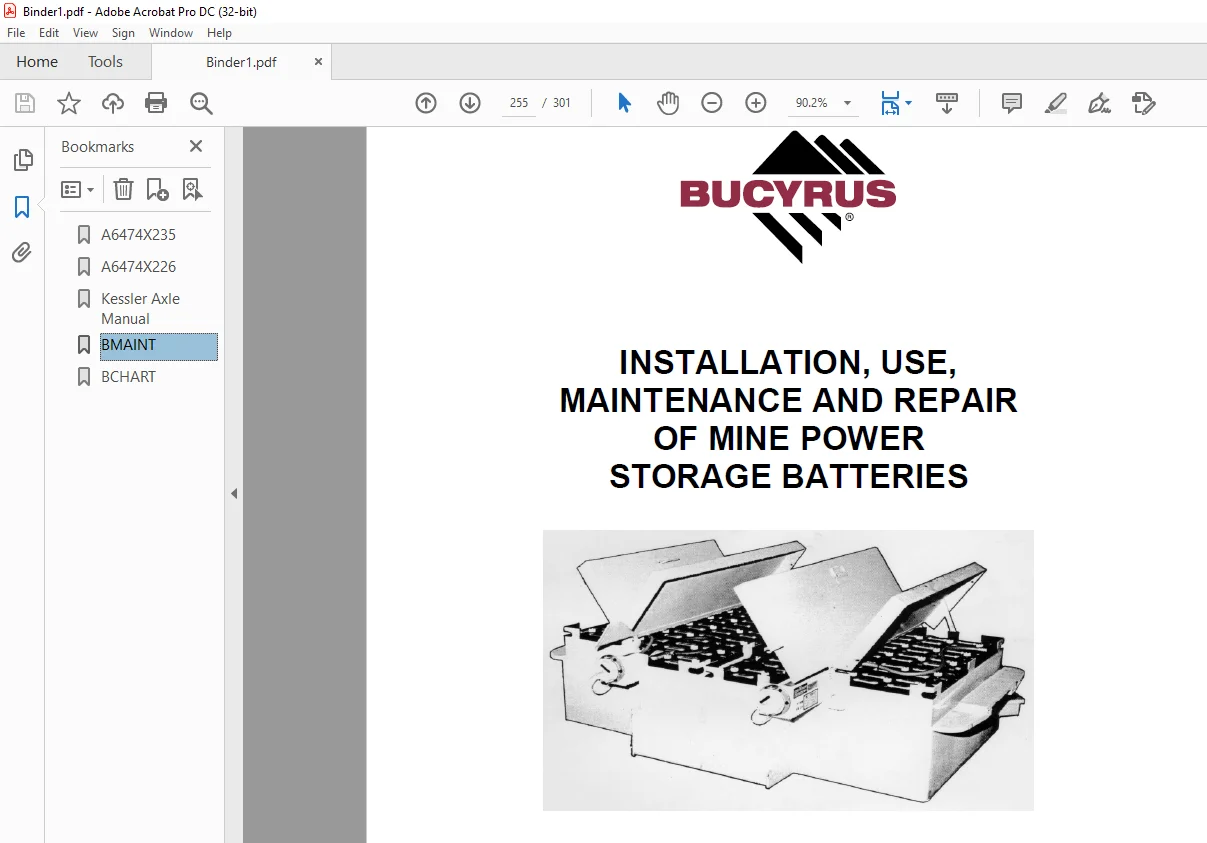
CAT Bucyrus MINE POWER STORAGE BATTERIES INSTALLATION, USE,MAINTENANCE AND REPAIR MANUAL
CAT Kessler Axle Service Manual 72.4665.3
CAT BUCYRUS 2000 DUAL AND SINGLE MOTOR SOLID STATE CONTROLLERS OPERATION AND TROUBLESHOOTING GUIDE MANUAL
FILE DETAILS:
CAT Bucyrus 488-6 and 488L UN-A-TRAC® Operation Manual – PDF DOWNLOAD
Language : English
Pages :301
Downloadable : Yes
File Type : PDF
IMAGES PREVIEW OF THE MANUAL:
TABLE OF CONTENTS:
CAT Bucyrus 488-6 and 488L UN-A-TRAC® Operation Manual – PDF DOWNLOAD
CAT Bucyrus 488-6 and 488L UN-A-TRAC® Operation Manual
1 About this manual
About this manual 1 3
Before starting to work 1 3
Who is this operating manual intended for? 1 3
What is the purpose of this operating manual? 1 4
Characters and symbols 1 5
2 Your safety
Your safety 2 3
Personnel 2 4
Operation 2 4
Installation and repair 2 4
Operating conditions 2 5
Intended use 2 5
Unauthorized use 2 5
Safety instructions 2 7
General rules: 2 7
Storage and transport 2 8
Pre-start inspection 2 8
Installation and start-up 2 9
Operation 2 9
Stopping 2 10
Maintenance and repair 2 10
Overview of the safety instructions 2 15
Chapter 3: Storage and transport 2 15
Chapter 4: Installation 2 15
Chapter 5: Operation 2 16
Chapter 6: Technical data 2 21
3 Storage and transport
Storage and transport 3 3
Storage 3 3
Storage of the machine and spare parts 3 3
Transport 3 4
Load units, dimensions, and weights 3 4
Before transport 3 5
4 Installation
Installation 4 3
Points to observe prior to installation 4 3
Who is allowed to carry out installation? 4 3
Which tools are required for installation? 4 3
Notes on installation 4 4
Pre-installation check list 4 5
Safety features 4 6
5 Operation
Operation 5 3
How to operate the UN-A-TRAC® 5 3
Who is allowed to operate the UN-A-TRAC® 5 3
When can operation be started? 5 3
Controls and indicators 5 4
Operator’s compartment – common 5 6
Operator’s compartment with control handle 5 12
Operator’s compartment with control station 5 15
Hazard zone 5 17
Starting procedure with control handle 5 18
Machine operation with control handle 5 19
Shutdown procedure with control handle 5 22
Starting procedure with control station 5 24
Shutdown procedure with control station 5 27
Towing a disabled machine 5 28
Battery change procedure 5 29
Instructions on the maintenance 5 35
Important notes 5 35
Before maintenance 5 35
Critical torque values 5 37
Lubricants, fluids and capacities 5 37
Specific lubrication and maintenance instructions 5 41
Every shift 5 41
Weekly 5 42
Monthly 5 53
Every three months 5 54
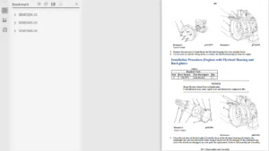
Major maintenance 5 61
Drive motor/gearbox removal and replacement 5 61
Tire/wheel installation procedure 5 63
Troubleshooting procedures 5 67
Hydraulic system (general) 5 68
Brakes 5 71
Hydraulic cylinders 5 73
Hydraulic pump 5 74
Valves 5 76
6 Technical data
Technical data 6 3
Tightening torques 6 5
Permissible data 6 11
Lubrication fluids and greases 6 11
7 For your information
For your information 7 3
Our service 7 3
Service address 7 3
Rebuild facility address 7 4
CAT Bucyrus MINE POWER STORAGE BATTERIES INSTALLATION, USE,MAINTENANCE AND REPAIR MANUAL
PREFACE 1
SYMBOLS AND SPECIAL NOTATIONS 3
MAJOR HAZARDS 5
SAFETY PRECAUTIONS AND GUIDELINES 7
OVERVIEW 7
MAINTENANCE 7
CHAPTER 1 – INTRODUCTION 8
SECTION I GENERAL 8
SECTION II DEFINITIONS 9
SECTION III DESCRIPTION AND CONSTRUCTION 9
SECTION IV PRINCIPLES OF OPERATION 13
CHAPTER 2 – INSTALLATION, USE, AND MAINTENANCE 16
SECTION I PREPARATION FOR USE 16
SECTION II ROUTINE MAINTENANCE 20
CHAPTER 3 – FIELD SERVICING AND REPAIR 25
SECTION I TROUBLESHOOTING 25
SECTION II REPAIRING BATTERIES 26
CHAPTER 4 – HEALTH AND SAFETY 35
SECTION I BATTERY HAZARDS 35
SECTION II SAFETY PROCEDURES 35
CHAPTER 5 – STORAGE AND SHIPMEMT 39
CAT Kessler Axle Service Manual 72.4665.3
CAT BUCYRUS 2000 DUAL AND SINGLE MOTOR SOLID STATE CONTROLLERS OPERATION AND TROUBLESHOOTING GUIDE MANUAL
DESCRIPTION PAGE #
PREFACE 2
SYMBOLS AND SPECIAL NOTATIONS 3
MAJOR HAZARDS 5
SAFETY PRECAUTIONS AND GUIDELINES 6
OVERVIEW 6
MAINTENANCE 6
INTRODUCTION 7
BUCYRUS 2000: INNOVATIVE SPEED CONTROL BY BUCYRUS AMERICA, INC 7
GENERAL SPECIFICATIONS 12
FAIL-SAFE OPERATION WILL INCLUDE THE FOLLOWING: 12
DESCRIPTION OF FEATURES 13
BUCYRUS 2000 MOTOR CONTROLLER CONSIST OF: 13
BUCYRUS 2000 MOTOR IGBT PANEL (POWER CONNECTIONS) 13
MICROPROCESSOR BASED LOGIC CARD (CONTROL INPUTS) 13
CONFIGURATION JUMPER TABLE 15
OPTIONAL DASHBOARD DISPLAY FEATURES (SEE FIGURE 9) 15
FAULT MESSAGE CHART 16
OPTIONAL HAND HELD DIAGNOSTICS/CALIBRATOR UNIT 18
PERSONALITY ADJUSTMENT PROCEDURE 19
TRACTION PERSONALITIES (CONTROLLER ADJUSTMENTS) 19
TRACTION STATUS DISPLAY 21
TRACTION TEST DISPLAY 23
TRACTION BDI DISPLAY 24
ERROR CODE LEGEND (STATUS DISPLAY) 25
TROUBLESHOOTING 26
IGBTMEASUREMENTS 27
INDIVIDUAL IGBT MEASUREMENTS 28
DIODEMEASUREMENTS 29
DIODEMEASUREMENTS 30
PANEL MEASUREMENTS 31
DRIVER MEASUREMENTS 32
IGBT DUAL MOTOR PANEL, FIGURE 16 34
IGBT SINGLEMOTOR PANEL,FIGURE 17 35
IGBT HEAT SINK ASSEMBLY, FIGURE 18 36
SINGLE MOTOR PANEL HARNESS ASSEMBLY, FIGURE 19 37
DUAL MOTOR PANEL HARNESS ASSEMBLY, FIGURE 20 38
DASHBOARD DISPLAY, FIGURE 21 39
DUAL “Y” HARNESS, FIGURE 22 40
HARNESS FOR DASHBOARD DISPLAY, FIGURE 23 41
CALIBRATOR UNIT, FIGURE 24 42
BUCYRUS 2000 PUMPMOTOR SHUNT, FIGURE 25 42
BUCYRUS 2000 PANELWIRING HARNESS, FIGURE 26 43
Need help? Contact: [email protected]
S.M