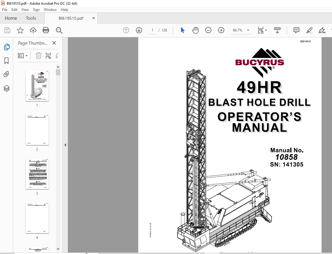
Cat Bucyrus 49HR Blast Hole Drill Operator’s Manual SN 141305 – PDF DOWNLOAD
$27.95
Cat Bucyrus 49HR Blast Hole Drill Operator’s Manual SN 141305 – PDF DOWNLOAD
Description
Cat Bucyrus 49HR Blast Hole Drill Operator’s Manual SN 141305 – PDF DOWNLOAD
FILE DETAILS:
Cat Bucyrus 49HR Blast Hole Drill Operator’s Manual SN 141305 – PDF DOWNLOAD
Language : English
Pages : 126
Downloadable : Yes
File Type : PDF
IMAGES PREVIEW OF THE MANUAL:
DESCRIPTION:
Cat Bucyrus 49HR Blast Hole Drill Operator’s Manual SN 141305 – PDF DOWNLOAD
GENERAL INFORMATION:
- This manual is designed to assist the owner in the operation and maintenance of this machine. By
following easy to understand step-by-step procedures the operators and maintenance personnel can
perform all tasks in a safe manner. When a systematic and thorough maintenance/service procedure
is used for this machine, a minimum of unplanned downtime and more reliable operation will result. - THIS MANUAL IS NOT THE PARTS BOOK, and cannot be used as reference material to order parts. A
separate, detailed parts book has been supplied. Please carefully read the instructions in it. All
parts are listed by group and/or product code numbers with the associated item/part numbers for
THIS SPECIFIC MACHINE. Order parts in the exact quantity needed. RIGHT and LEFT refer to machine
locations as viewed by the operator sitting in the operator’s seat in the cab. Please state the
correct machine SERIAL NUMBER when corresponding or contacting the factory service or parts
departments. Records on each machine are filed by serial number and when given this number, your
machine’s specific design and original equipment is accessed quickly by the Bucyrus International
parts representative. Periodic additions or revisions may be made to this manual.
• The employment of qualified maintenance personnel, through a scheduled maintenance
program, is the best way to minimize machine downtime and maximize productivity of
equipment.
• Keep hands, feet, and clothing away from rotating parts.
• Wear a hard hat, safety shoes and protective lenses at all times.
• Replace any and all safety and warning placards if they are defaced or removed from the machine.
• Think before you act. Carelessness is one luxury the service man cannot afford.
• Excessive or repeated skin contact with sealants or solvents may cause skin irritation. In case
of skin contact refer to the Material Safety Data Sheet (MSDS) for that material and the suggested
method of cleanup.
• Inspect safety catches (keepers) on all hoist hooks. Do not take a chance, the load could slip
off of the hook if they are not functioning properly.
• If a heavy item begins to fall, let it fall, don’t try to catch it.
• Keep your work area organized and clean. Wipe up oil or spills of any kind immediately. Keep
tools and parts off of the ground. Eliminate the possibility of a fall, slipping or tripping.
• Floors, walkways and stairways must be clean and dry. After fluid draining operations be sure
all spillage is cleaned up.
• Electrical cords and wet metal floors make a dangerous combination.
• Regularly inspect for any loose bolts or locking devices and properly secure them.
• Use extreme caution while working near any electrical lines or equipment whether it be high or
low voltage. Never attempt electrical repairs unless you are qualified.
• Check limit switches for proper operation.
• After servicing, be sure all tools, parts or servicing equipment are removed from the machine
and secured in an appropriate storage area.
• Mechanical Brakes are designed for use as static holding brakes only. Use as a motion (dynamic)
brake in emergency situations only.
• Use proper interior and exterior lighting.
• Install and maintain proper grounding and ground fault protection systems.
• Perform functional tests of all safety circuits.
• Allow electrical inspection and maintenance to be performed only by a qualified electrician.
• Use extreme caution when working around drilled holes.
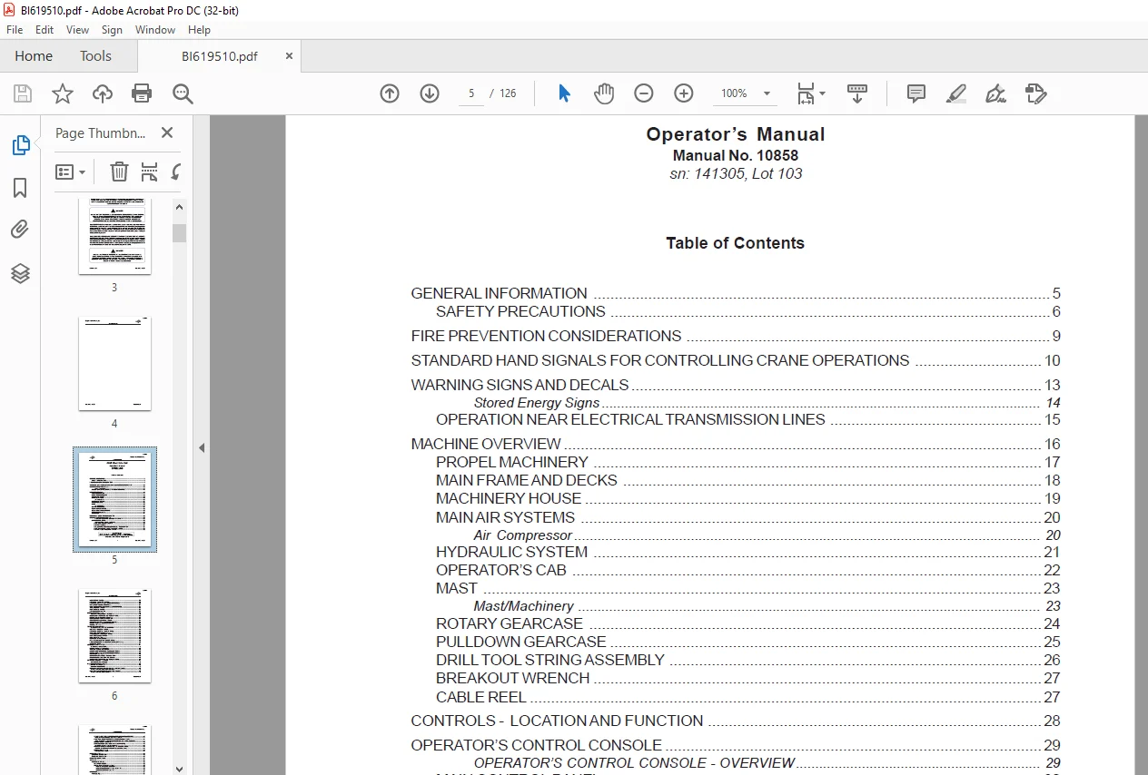
TABLE OF CONTENTS:
Cat Bucyrus 49HR Blast Hole Drill Operator’s Manual SN 141305 – PDF DOWNLOAD
GENERAL INFORMATION 5
SAFETY PRECAUTIONS 6
FIRE PREVENTION CONSIDERATIONS 9
STANDARD HAND SIGNALS FOR CONTROLLING CRANE OPERATIONS 10
WARNING SIGNS AND DECALS 13
Stored Energy Signs 14
OPERATION NEAR ELECTRICAL TRANSMISSION LINES 15
MACHINE OVERVIEW 16
PROPEL MACHINERY 17
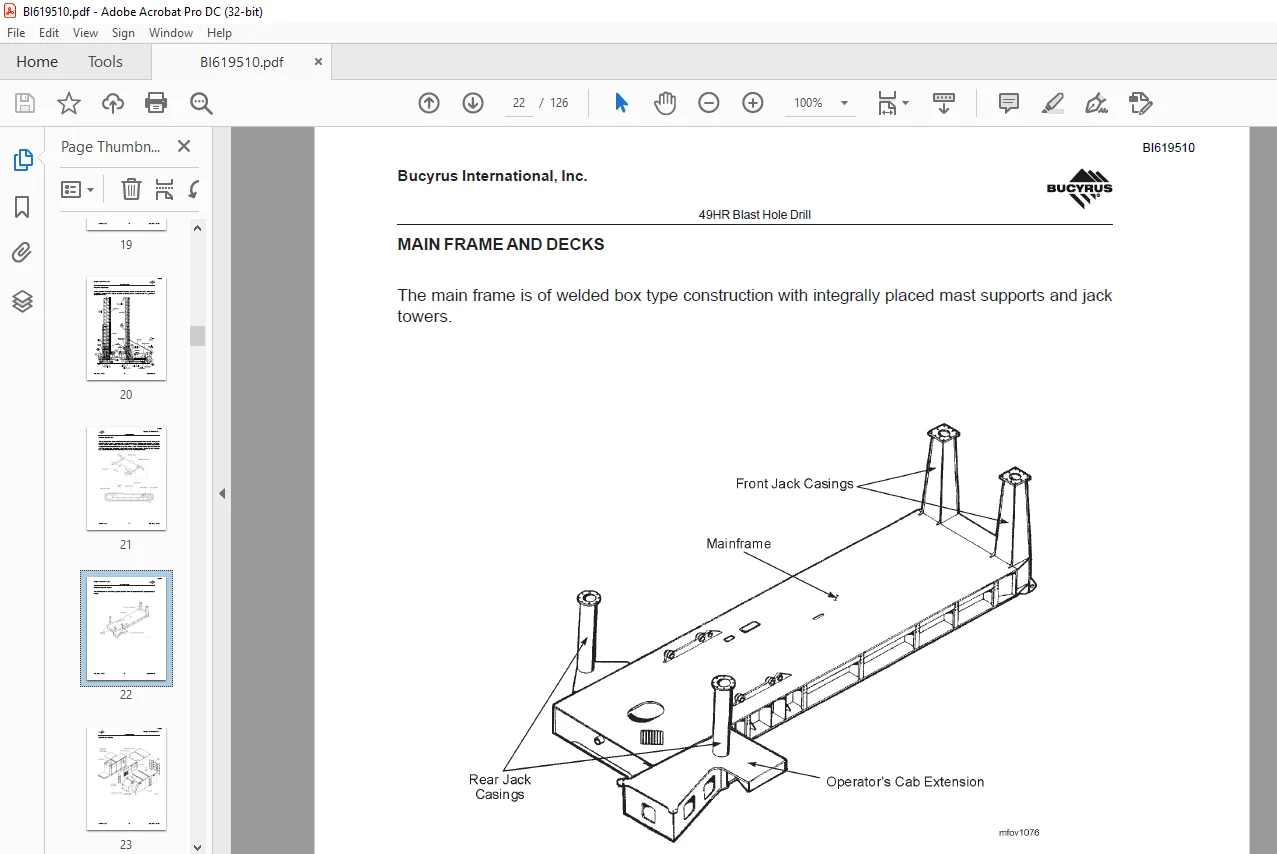
MAIN FRAME AND DECKS 18
MACHINERY HOUSE 19
MAIN AIR SYSTEMS 20
Air Compressor 20
HYDRAULIC SYSTEM 21
OPERATOR’S CAB 22
MAST 23
Mast/Machinery 23
ROTARY GEARCASE 24
PULLDOWN GEARCASE 25
DRILL TOOL STRING ASSEMBLY 26
BREAKOUT WRENCH 27
CABLE REEL 27
CONTROLS – LOCATION AND FUNCTION 28
OPERATOR’S CONTROL CONSOLE 29
OPERATOR’S CONTROL CONSOLE – OVERVIEW 29
MAIN CONTROL PANEL 30
MAIN CONTROL PANEL – OVERVIEW 30
HOIST/PULLDOWN RHEOSTAT 30
ROTARY RHEOSTAT 31
DRILL/PROPEL CONTROLS ON AND OFF PUSH-BUTTON 31
HOIST/PULLDOWN SPEED SELECTOR SWITCH 32
ROTARY SPEED SELECTOR SWITCH 32
HOIST BRAKE SWITCH 33
PIPE RACK SELECTOR SWITCH 33
PIPE RACK JOYSTICK (LEFT CRAWLER PROPEL) 33
WINCH/MAST SELECTOR SWITCH 34
MAST/WINCH JOYSTICK (RIGHT CRAWLER PROPEL) 34
TOOL WRENCH SWITCH 35
DUST CURTAIN SWITCH 35
BIT VIEW HATCH SWITCH 35
PROPEL CONTROL PANEL 36
PROPEL CONTROL PANEL – OVERVIEW 36
EMERGENCY STOP PUSH-BUTTON (OPTIONAL) 36
PROPEL SPEED SELECTOR SWITCH 37
COMPRESSOR STOP PUSH-BUTTON 37
COMPRESSOR VENT/DRILL SWITCH 37
HEATER/VENT/AIR CONDITIONER CONTROLS 37
OPERATING MODE SELECTOR SWITCH 37
PROPEL JOYSTICKS 38
SELECTOR SWITCH PANEL 38
SELECTOR SWITCH PANEL – OVERVIEW 38
BREAKOUT WRENCH SWITCH 39
PIPE POSITIONER SWITCH (OPTIONAL) 39
DUST SEAL SWITCH (OPTIONAL) 39
A-FRAME LOCK SWITCH (OPTIONAL) 39
MAST BRACE LOCK SWITCH 40
MAST LOCK SWITCH 40
BOARDING STAIRS SWITCH 40
PEDESTAL HEATER SWITCH (OPTIONAL) 40
FIRE SUPPRESSION SYSTEM INDICATORS (OPTIONAL) 40
RADIO (OPTIONAL) 41
LEVELING CONTROL PANEL 41
LEVELING CONTROL PANEL 41
MANUAL LEVELING JOYSTICKS 42
AUTOMATIC LEVELING SWITCH 42
WATER INJECTION ON/OFF SWITCH (OPTIONAL) 42
WATER INJECTION FLOW CONTROL (OPTIONAL) 42
HORN PUSH-BUTTON 43
DEPTH INDICATOR RESET PUSH-BUTTON 43
PROGRAMMED DRILL CONTROL SWITCH 43
EMERGENCY STOP PUSH-BUTTON (OPTIONAL) 43
OPERATOR’S DISPLAY TERMINAL 44
OPERATOR’S DISPLAY PANEL 44
MACHINERY HOUSE CONTROLS 45
LIGHTING LOAD CENTER 45
LIGHTING LOAD CENTER 45
CONTROLS LOCATED ON LOW VOLTAGE START CABINET 46
TYPICAL LOW VOLTAGE START CABINET 46
CONTROLS LOCATED ON LOW VOLTAGE CABINET 46
TYPICAL LOW VOLTAGE CABINET 46
CONTROL LOCATED ON PROGRAMMABLE CONTROLLER CABINET 47
TYPICAL PROGRAMMABLE CONTROL CABINET 47
HOIST/PULLDOWN AND ROTARY DRIVE CONTROL CABINETS 47
TYPICAL HOIST/PULLDOWN AND ROTARY DRIVE CONTROL CABINETS 47
MISCELLANEOUS CONTROLS 48
PORTABLE REMOTE PROPEL STATION (OPTIONAL) 48
PORTABLE REMOTE PROPEL STATION 48
HYDRAULIC RESERVOIR REMOTE FILL CONTROL PANEL 49
HYDRAULIC RESERVOIR REMOTE FILL CONTROL PANEL 49
LUBE CONTROL PANEL 49
LUBE CONTROL PANEL 49
PRESTART CHECKS 50
EXTERNAL INSPECTION 50
ONBOARD INSPECTION 52
PRESTART LUBRICATION 54
START-UP 55
MACHINE START UP 55
MACHINERY CHECK 56
BREAK-IN OF NEW COMPONENTS 56
ROTARY DRIVE UNIT BREAK-IN 56
HOIST/PULLDOWN GEARCASE BREAK-IN 56
ELECTRIC MOTOR BREAK-IN 56
OPERATION 57
PROPELLING 57
DEFINITIONS 57
PROPEL PROCEDURE 58
PROPEL CONTROLS – OVERVIEW 59
STRAIGHT PROPEL 60
GRADUAL RIGHT HAND TURN 60
GRADUAL LEFT HAND TURN 61
COUNTER-ROTATION LEFT HAND TURN 62
ENSURE GRADUAL TURNS ARE MADE – 15O INCREMENTS 62
TOWING PROCEDURE 64
TOWING PROCEDURE 64
CABLE REEL OPERATION 66
CABLE REEL 66
LEVELING 67
LEVELING CONTROLS 68
MAST RAISING AND LOWERING 69
MAST RAISING 69
MAST RAISING/LOWERING CONTROLS 70
MAST LOWERING 71
MAST CONTROLS TO ADJUST FOR ANGLE DRILLING 71
PULLDOWN MACHINERY OPERATION 73
HOIST/PULLDOWN CONTROLS 73
AUXILIARY WINCH OPERATION 74
WINCH OPERATION CONTROLS 74
PIPE RACK OPERATION 75
PIPE RACK OPERATING CONTROLS 75
PIPE RACK OPERATION 76
TOOL HANDLING 78
PIPE LOADING AND UNLOADING 78
DRILL TOOL STRING ASSEMBLY 80
TOOL STRING 80
STABILIZER INSTALLATION 81
DRILL PIPE INSTALLATION CONTROLS 81
BREAKOUT WRENCH OPERATION 84
DRILL TOOL STRING DISASSEMBLY 86
ADDING ADDITIONAL DRILL PIPE 88
REMOVAL OF MULTIPLE SECTION DRILL PIPE 89
ANGLE DRILLING 90
ANGLE DRILLING EQUIPMENT 90
PIPE POSITIONER 91
JIB CRANE 92
DUST SUPPRESSION SYSTEM OPERATION 93
WATER INJECTION SYSTEM 94
DRILLING 95
VERTICAL DRILLING 95
CONTROLS UTILIZED WHILE DRILLING 95
STARTING THE HOLE (COLLARING) 96
NORMAL DRILLING 98
ENDING THE HOLE 99
ENDING THE HOLE (MULTIPLE PIPE SECTIONS) 100
DRILLING DIFFICULT FORMATIONS 100
UNCONSOLIDATED MATERIALS 101
WET OR STICKY FORMATIONS 104
ANGLE DRILLING 104
PROGRAMMED DRILL CONTROL DRILLING 105
PROGRAMMED DRILL CONTROLS UTILIZED 105
PREPARING TO MOVE 106
MACHINE SHUTDOWN 108
SHUT DOWN PROCEDURE 108
SHORT TERM STORAGE 109
LONG TERM STORAGE 110
ATTENDED LONG TERM STORAGE 111
UNATTENDED LONG TERM STORAGE 111
TOOL RECOVERY 112
DRILL STABILITY CHARTS 114
Drill Stability Chart – Special Propel Conditions 114
Drill Stability Chart – Typical Propel Conditions 115
TYPICAL MACHINE SPECIFICATIONS 116
GENERAL ESTIMATED COMPONENT WEIGHTS 119
Questions? Email us: [email protected]
PLEASE NOTE:
- This is the SAME manual used by the dealers to troubleshoot any faults in your vehicle. This can be yours in 2 minutes after the payment is made.
- Contact us at [email protected] should you have any queries before your purchase or that you need any other service / repair / parts operators manual.
S.V