CAT BUCYRUS-ERIE 49-RII Diesel Electric Blast Hole Drill MECHANICAL MAINTENANCE MANUAL BI005470 – PDF DOWNLOAD
$25.95
CAT BUCYRUS-ERIE 49-RII Diesel Electric Blast Hole Drill MECHANICAL MAINTENANCE MANUAL BI005470 – PDF DOWNLOAD
Description
CAT BUCYRUS-ERIE 49-RII Diesel Electric Blast Hole Drill MECHANICAL MAINTENANCE MANUAL BI005470 – PDF DOWNLOAD
FILE DETAILS:
CAT BUCYRUS-ERIE 49-RII Diesel Electric Blast Hole Drill MECHANICAL MAINTENANCE MANUAL BI005470 – PDF DOWNLOAD
Language : English
Pages : 186
Downloadable : Yes
File Type : PDF
DESCRIPTION:
CAT BUCYRUS-ERIE 49-RII Diesel Electric Blast Hole Drill MECHANICAL MAINTENANCE MANUAL BI005470 – PDF DOWNLOAD
FOREWORD
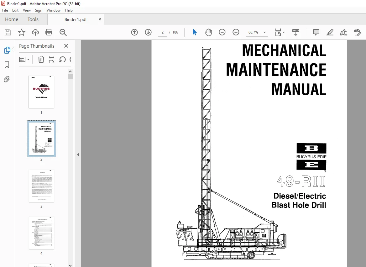
- The purpose of this manual is to provide information concerning the general maintenance of the 49-RII Diesel/Electric Rotary Blast Hole Drill. The Model 49-RII consists of three major units, the lower works, the mainframe and the mast. The lower works provides a foundation for the mainframe and contains the necessary equipment to propel the drill.
- The mainframe includes the hydraulic system, main air system, the diesel/electric drive, and the machinery house. The machinery house encloses the majority of the mechanical equipment necessary for the main air system, the hydraulic systems and electrical control systems.
- The machinery house is pressurized with filtered air to minimize dirt and heat build-up. The operator’s cab, mounted to the mainframe, includes the operator’s station, and encloses the majority of the controls necessary to operate the drill.
- The mast contains the drill pipe and drilling tools, the pipe racks, and the rotary and pulldown machinery. This manual consists of six chapters, each divided into sections. A table of contents is located in the front of the manual.
IMAGES PREVIEW OF THE MANUAL:
TABLE OF CONTENTS:
CAT BUCYRUS-ERIE 49-RII Diesel Electric Blast Hole Drill MECHANICAL MAINTENANCE MANUAL BI005470 – PDF DOWNLOAD
CHAPTER 1 MECHANICAL MAINTENANCE
SECTION 1 MAINTENANCE PROCEDURE
General 1 l 1
Maintenance Schedules and Reports 1 1 1
Safety 1 l 2
General 1 1 2
In operation Maintenance 1 l 2
Precautions Before and During Maintenance Work 1 1 2
SECTION 2 LOWER WORKS
Crawler Belts 1 2 1
Adjustment 1 2 1
Link Replacement 1 2 2
Belt Replacement 1 2 3
Lower Rollers 1 2 4
Upper Rollers 1 2 5
Take up Tumblers 1 2 5
Drive Tumbler 1 2 7
Planetary Gearbox 1 2 7
Crawler Frames 1 2 10
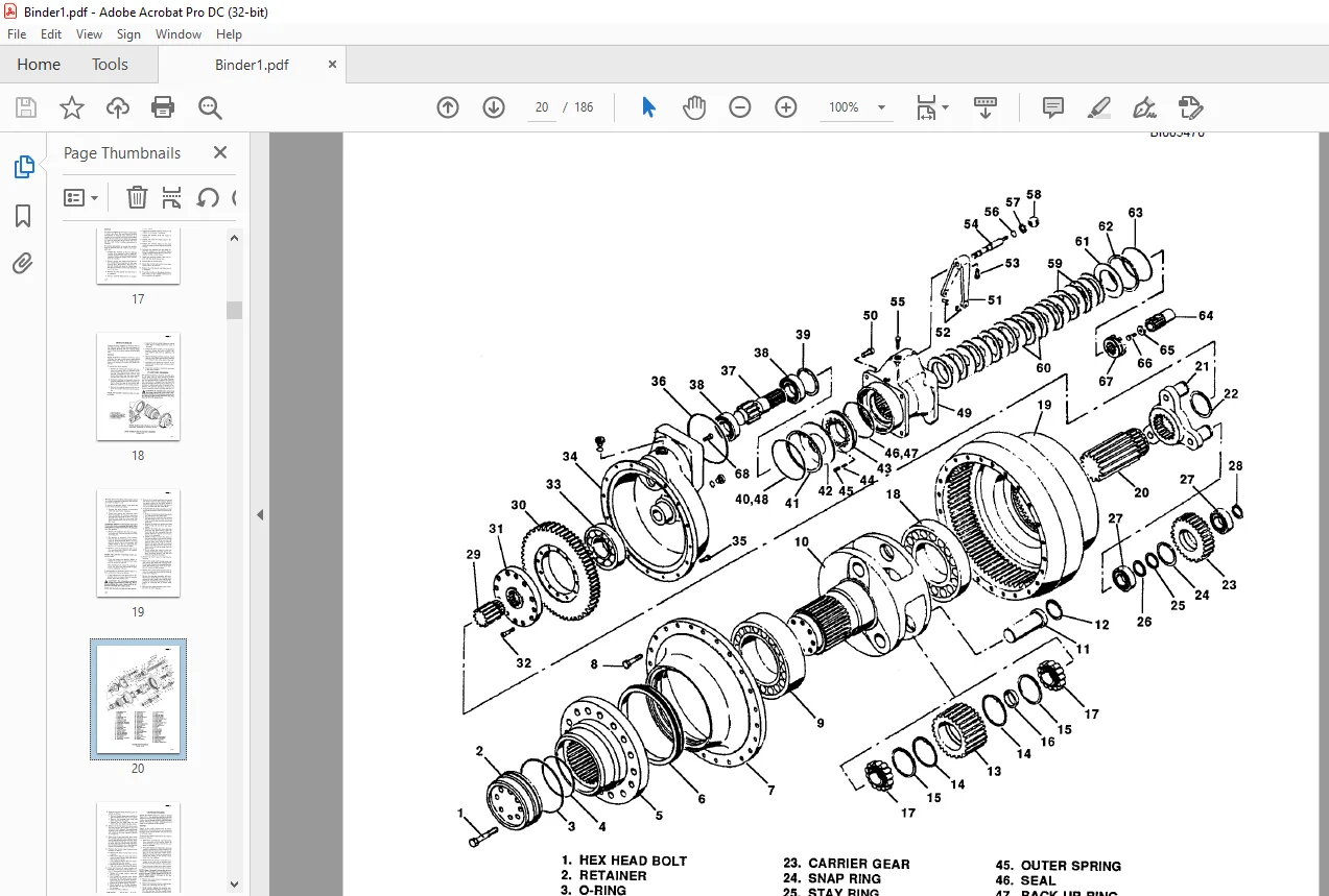
Axles 1 2 ll
SECTION 3 MAINFRAME
Mainframe 1 3 1
Bit Viewing Hatch 1 3 l
Mast A Frame 1 3 2
Leveling Jacks 1 3 2
Machinery House 1 3 5
House Pressurization Fan and Filter 1 3 6
Walkways and Ladders 1 3 6
Operator’s Cab 1 3 6
Operator’s Controls 1 3 7
Ventilation Unit 1 3 7
Hydraulic Pump Drive 1 3 7
Diesel Engine/Alternator Set 1 3 10
Diesel Engine Radiator 1 3 11
General Safety and Maintenance 1 3 11
Removal of Tubes 1 3 14
Installation of Tubes 1 3 14
Core with Center Tanks 1 3 15
External Cleaning 1 3 15
Diesel Engine Air Filter 1 3 15
Diesel Engine Saver 1 3 15
Hose Routing and Installation Precautions 1 3 15
SECTION 4 MAST
Mast Structure 1 4 1
Mast Safety Slings 1 4 2
Rotary Gearcase 1 4 2
Drive Shaft Adjustment 1 4 2
Repair 1 4 3
Rotary Motor 1 4 8
Rotary Coupling 1 4 8
Rotary/Pulldown Guide Frame 1 4 10
Guide Roller Adjustment 1 4 10
Repair 1 4 10
Pulldown Gearcase 1 4 15
Hoist Brake 1 4 19
Inspection 1 4 19
Brake Wear Adjustment 1 4 19
Replacement of Friction Discs 1 4 20
Disassembly of Magnet Body and Armature 1 4 20
Reassembly of Magnet Body and Armature 1 4 21
Pipe Racks 1 4 21
Tool Wrenches 1 4 24
Auxiliary Winch 1 4 25
Mast Braces 1 4 25
Repair 1 4 25
Adjustment 1 4 25
CHAPTER 2 HYDRAULIC SYSTEM
SECTION 1 SYSTEM OPERATION
Cylinder Circuit Hydraulic System 2 1 1
Propel Circuit Hydraulic System 2 1 1
SECTION 2 GENERAL MAINTENANCE
Hydraulic System Cleanliness 2 2 1
Oil Requirements 2 2 1
Oil and Filter Changes 2 2 1
Filter Maintenance 2 2 l
Weekly Maintenance Checks 2 2 2
Oil Reservoir Repairs 2 2 2
Hydraulic Oil Cooler 2 2 2
General Safety & Maintenance 2 2 2
Removal of Tubes 2 2 2
Installation of Tubes 2 2 4
External Cleaning 2 2 4
Leveling Jack Counterbalance Valve Pressure Relieving Procedure 2 2 4
Rear Jacks 2 2 4
Front Jack 2 2 5
Prestart Inspection 2 2 5
Hydraulic Systems Tests 2 2 5
Propel Pump Charge Pressure Check 2 2 6
Control Pressure Check 2 2 6
Propel Enable Valve and Low Speed Select Check 2 2 6
Jack Cylinder Check in Manual Mode 2 2 7
Flow Control Check 2 2 7
Jack Cylinder Drift Test 2 2 8
Brake Release Pressure Check 2 2 8
Propel Brake Emergency Release Check 2 2 8
Propel Pump Main Relief Pressure Check 2 2 8
Crawler Function Check 2 2 9
Bit Viewing Hatch Check 2 2 9
Boarding Stair Check 2 2 9
Main Flow Valve Check 2 2 9
Breakout Wrench and Tool Wrench Check 2 2 9
Dust Curtain Cylinders 2 2 9
Dust Seal Slider 2 2 9
Mast Lock (Station 6 of 7 station manifold) 2 2 9
Mast Brace Lock Cylinders (Station 4 of 7 station manifold) 2 2 10
A Frame Lock Cylinders (Station 5 of 7 Station Manifold) 2 2 10
Mast Lock Constant Pressure Check 2 2 10
Mast Brace Constant Pressure Check 2 2 10
A Frame Lock Constant Pressure Check 2 2 10
Mast Raise/Lower 2 2 10
Auxiliary Winch 2 2 11
Pipe Rack Position 2 2 11
Troubleshooting Leveling Jack Flow OCntrol Valve for Failure 2 2 11
Pipe Rack Lock and Gate Cylinder Port Relief Setting 2 2 11
Check Jacks in Auto Level Mode 2 2 12
Hydraulic Lube Drive Pressure Reducing Valve Setting 2 2 12
Test Point Locations 2 2 13
CHAPTER 3 AIR SYSTEM
SECTION 1 SYSTEM OPERATION
MAIN AIR SYSTEM 3 l 1
SECTION 2 GENERAL MAINTENANCE
Main Air System 3 2 1
General 3 2 1
Intake Air Filter 3 2 1
Filter Service 3 2 2
Compressor Oil Cooler 3 2 2
Description 3 3 1
Coupling Alignment 3 3 1
SECTION 3 ROTARY SCREW COMPRESSOR
(A C COMPRESSOR CORP KS 31 LU OR KS 27 LU)
Parallel Misalignment 3 3 2
Angular Misalignment 3 3 2
Start Up Procedure 3 3 2
Shutdown 3 3 3
Controls and Instruments 3 3 3
Air Pressure Control System 3 3 3
Reduced Unloaded Horsepower Feature 3 3 8
Variable Volume Feature (Optional) 3 3 10
Lubrication System 3 3 11
Compression Oil System 3 3 11
Oil Specifications 3 3 12
Filling Oil System (Initially) 3 3 12
Oil Level Gauge 3 3 12
Adding Oil Between Changes 3 3 12
Oil Change Intervals 3 3 12
Draining Oil System 3 3 12
Refilling Oil System 3 3 13
Compressor Oil Strainer and Filters 3 3 13
Compressor Oil Cooler 3 3 14
Thermostatic Control Valve 3 3 14
Compressor Oil Separator 3 3 15
Air Filters 3 3 15
Maintenance Schedule 3 3 16
CHAPTER 4 DUST CONTROL
SECTION 1 GENERAL MAINTENANCE
Drilling Platforms and Dust Curtains 4 1
Water Injection 4 1
CHAPTER 5 LUBRICATION
SECTION 1 LUBRICATION PROCEDURES
General 5 1 1
Lubricant Cleanliness 5 1 1
Lubrication Points 5 1 1
Lubrication Benchmarks 5 1 8
SECTION 2 LINCOLN AUTOMATIC SYSTEM
Troubleshooting Systems 5 2 1
Air Locks 5 2 1
Dirty Supply Lines 5 2 1
All Injectors Do Not Function Properly 5 2 1
After Venting, The Indicator Stems On The Injectors Do Not Return To Their
Normal Position 5 2 1
Lube Pump 5 2 2
Lubrication 5 2 2
CHAPTER 6 TROUBLESHOOTING 6 1 1
APPENDICES
APPENDIX Al GEAR INSPECTION
General lA 1
APPENDIX A2 BOLT TORQUING
Torque Wrench Method 2A 1
Turn of the Nut Method 2A 2
APPENDIX A3 PINION, BRAKE DRUM AND COUPLING INSTALLATION
Removal from Shaft 3A 1
Mounting on Shaft 3A 1
APPENDIX A4 LUBE BENCHMARKS
MPG Multi Purpose Type Grease 4A 1
ACSL Air Compressor (Screw Type) Lubricant 4A 2
DPTL Drill Pipe Thread Lubricant 4A 3
MPO Multi Purpose Oil 4A 4
OGL Open Gear Lubricant 4A 5
RGL Regular Type Gear Lubricant 4A 7
RWRL Running Wire Rope Lubricant 4A 10
HYDO Hydraulic Oil 4A 11
APPENDIX A5 RECOMMENDED PROCEDURES FOR MAINTENANCE WELDING OF
PRINCIPAL STRUCTURES ON BLAST HOLE DRILLS
General 5A 1
Maintenance Welding 5A 1
Structural Materials 5A 1
Welding Electrodes 5A 2
Preheat Requirements 5A 2
Removal of Cracks 5A 3
Weld Groove Preparation 5A 3
Drill Pipe Welding 5A 4
Welding Technique 5A 5
Weld Inspection 5A 5
Repair of Broken Parts 5A 5
APPENDIX A6 PREVENTIVE MAINTENANCE CHECK LIST
Level 1 Inspection 6A 1
Level 2 Inspection 6A 5
Level 3 Inspection 6A 7
APPENDIX A7 SPECIAL FITS 7A 1
APPENDIX AS AEROQUIP ORS CONNECTIONS 8A 1
Questions? Email us: [email protected]
https://vimeo.com/865830473?share=copy
PLEASE NOTE:
- This is the same manual used by the dealers to diagnose and troubleshoot your vehicle
- You will be directed to the download page as soon as the purchase is completed. The whole payment and downloading process will take anywhere between 2-5 minutes
- Need any other service / repair / parts manual, please feel free to contact [email protected] . We still have 50,000 manuals unlisted
S.M