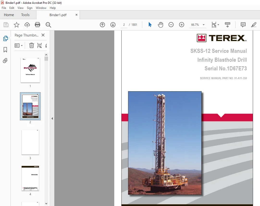
Cat Bucyrus SKSS-12 Infinity Blasthole Drill Service Manual SN 1D67E73 – PDF DOWNLOAD
$35.95
Cat Bucyrus SKSS-12 Infinity Blasthole Drill Service Manual SN 1D67E73 – PDF DOWNLOAD
Description
Cat Bucyrus SKSS-12 Infinity Blasthole Drill Service Manual SN 1D67E73 – PDF DOWNLOAD
FILE DETAILS:
Cat Bucyrus SKSS-12 Infinity Blasthole Drill Service Manual SN 1D67E73 – PDF DOWNLOAD
Language : English
Pages : 1801
Downloadable : Yes
File Type : PDF
IMAGES PREVIEW OF THE MANUAL:
DESCRIPTION:
Cat Bucyrus SKSS-12 Infinity Blasthole Drill Service Manual SN 1D67E73 – PDF DOWNLOAD
Safety:
The Rotary Drill is a heavy moving machine with a mast which raises vertically for drilling. Like
all moving objects and reach extending devices, there are potential hazards associated with its
use. These hazards will be minimised if the machine is properly inspected and maintained. The
maintainers must read this manual and have been trained to use the machine in an appropriate and
safe manner. Should any questions arise concerning the maintenance or operation of the machine
contact Reedrill in your state or territory.
There are many personal hazards and dangers associated with working on and around a drill rig. If
the safety instructions outlined in this section are adhered to, risk of injury or harm to yourself
and others will be significantly reduced. In this section and those that follow, the word:
• DANGER means that severe injury or death will result from failure to follow instruction
• WARNING means that severe injury or death can result from failure to follow instruction
• CAUTION means that minor injury or property damage can result from failure to follow
instruction
• NOTE means that special attention should be given to the instruction
Personal Protective Equipment:
Ensure that the minium PPE is worn at all times when operating or maintaining the machine. Specific
PPE may be required when undertaking some tasks or repairs. For example working at height, welding
or grinding repairs.
Noise:
The Rotary Drill generates high noise while it is in operation therefore, hearing protection is
mandatory whenever working in the vicinity of the drill.
Electrical Contact:
The Mines Regulation 5.28 states that unless minimum clearances under and in the vicinity of
overhead power lines in accordance with AS 3007.5 can be assured, no drilling activity can take
place within 10 meters any electrical power-line.
Overhead and Buried Utilities:
Should be located, noted and emphasised on all drilling location plans and drilling assignment
sheets.
Whenever overhead power lines exist on or near a drilling site or project, consider all wires to be
live and dangerous.
Watch for sagging power lines before entering a site. Do not lift power lines to gain entrance.
Before raising a drill rig mast on a site in the vicinity of power lines, walk completely around
the rig. Determine what the minimum distance from any point on the drill rig to the nearest power
line will be when the mast is raised or being raised.
Do not raise the mast or operate the drill rig within a minimum of 10 meters of any electrical
power line or underground utility without a permit indicating “danger zones” and minimum
clearances.
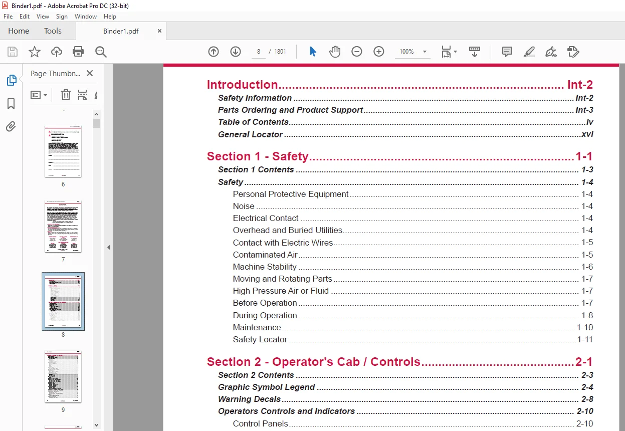
TABLE OF CONTENTS:
Cat Bucyrus SKSS-12 Infinity Blasthole Drill Service Manual SN 1D67E73 – PDF DOWNLOAD
Introduction Int-2
Safety Information Int-2
Parts Ordering and Product Support Int-3
Table of Contents iv
General Locator xvi
Section 1 – Safety 1-1
Section 1 Contents 1-3
Safety 1-4
Personal Protective Equipment 1-4
Noise 1-4
Electrical Contact 1-4
Overhead and Buried Utilities 1-4
Contact with Electric Wires 1-5
Contaminated Air 1-5
Machine Stability 1-6
Moving and Rotating Parts 1-7
High Pressure Air or Fluid 1-7
Before Operation 1-7
During Operation 1-8
Maintenance 1-10
Safety Locator 1-11
Section 2 – Operator’s Cab / Controls 2-1
Section 2 Contents 2-3
Graphic Symbol Legend 2-4
Warning Decals 2-8
Operators Controls and Indicators 2-10
Control Panels 2-10
Right Hand Control Panel 2-11
Instrument Panel and Circuit Breakers 2-12
Circuit Breakers 2-12
Light Switches 2-13
Instrument Panel 2-13
System Pressure Guage Panel 2-14
Left Hand Control Panel 2-16
Foot Control Pedals 2-22
Cab Foot Controls 2-22
Thread Grease Switch 2-22
Pipe Safety Arm Override Switch 2-22
Air Conditioner 2-23
T8 Series Split System Air Conditioning Manual 2-23
BI620421
viii SKSS Introduction
Contents
Section 3 – Main Frame / Crawlers 3-1
Section 3 Contents 3-3
Main Frame Repair – General 3-5
Main Frame Repair 3-5
Leveling Jacks 3-6
Leveling Jacks 3-6
Leveling Jack Cylinders 3-7
Mast Elevating Cylinders 3-8
Mast Elevating Cylinders 3-9
Remove 3-10
Repair 3-10
Replace 3-10
Crawler Assembly 3-11
Crawler Component Repair 3-12
Metric Bolt Torque Specifications 3-13
Track Maintenance 3-14
Before Operating the Machine 3-14
General Maintenance 3-14
Track Tension Adjustment 3-15
Hydraulic Tensioner 3-16
Description 3-17
Nitrogen Tensioner 3-18
Hydraulic Tensioner 3-19
Repair 3-19
Nitrogen Tensioner Assembly 3-20
Nitrogen Tensioner – Fitting Instructions 3-21
Nitrogen Tensioner – Pressure Check 3-23
Nitrogen Tensioner – Pressure Release 3-23
Track Chain – Separate 3-24
Track Chain – Repair 3-25
Track Link – Repair & Replace 3-25
Track Link – Description 3-26
Track Shoes Installation 3-27
Track Link Position 3-27
Track Shoe – Mounting to Tracsk Chain 3-28
Track Shoe Bolt Torque (Direct Torque Method) 3-29
Track Shoe Bolt Torque (Torque Turn Method) 3-30
Track Chain and Shoe Installation 3-31
Track Chain with Shoes 3-31
Track Chain & Shoe – Assembly & Installation 3-31
Final Drive 3-33
Final Drive – General Description 3-33
Final Drive Unit Removal 3-34
Removal from Track Frame 3-34
BI620421
SKSS Introduction ix
Contents
Final Drive Unit Installation 3-35
Installation into Track Frame 3-35
Final Drive Maintenance 3-36
Oil Check / Change 3-36
Final Drive Oil 3-37
Specifications 3-37
Recommended Oil 3-37
Final Drive Assembly 3-38
Parking Brake – Description 3-39
Final Drive – Disconnect & Parking Brake 3-40
Towing Procedure – Gear Drive Disconnect 3-41
Parking Brake – Removal & Installation 3-41
Idler Unit Assembly 3-42
Idler Unit – Assembly 3-44
Idler Unit Removal 3-48
Idler Unit – Removal 3-48
Track and Support Rollers 3-50
General Description 3-50
Track Roller – Removal & Disassembly 3-52
Track and Support Roller – Assembly 3-54
Track and Support Roller – Test and Install 3-55
Auxiliary Crane 3-57
Hydraulic Crane (Auxiliary Crane) 3-57
Load Lift Capacities 3-57
Maintenance 3-58
Section 4 – Engine / Drive Train / Compressor 4-1
Section 4 Contents 4-3
Power Group Locator 4-6
Cummins Engine 4-7
Engine Fuel System 4-8
Construction 4-9
Combo Fuel Filter Head & Pump Manifold 4-10
FS1006 Fuel Filter with Water Separator 4-10
Fuel Manifold with Integrated FSO Valve 4-11
Fuel Connections 4-11
Pre Filters 4-12
Wiring with EFS Power Relay 4-12
Pressure and Temperature Sensors 4-12
Operation 4-13
QST30 Electric Fuel Supply System 4-14
Oil Reserve Systems 4-16
Engine Oil Reserve System (Basic Circuit) 4-16
LED Monitor Readings 4-17
BI620421
SKSS Introduction
Contents
Adjustment of Running Oil Level 4-17
Oil Reserve Basic Circuit 4-18
Oil Pressure Switch 4-18
Oil Reserve System 4-18
Troubleshooting 4-19
Maintenance 4-19
Engine and Compressor Air Cleaner 4-20
Engine and Compressor Air Cleaner Service 4-21
Compressor Assembly 4-24
Flexible Drive Coupling 4-25
Flexible Drive Coupling Service 4-25
Pump Drive 4-27
Pump Identification 4-27
Pump Drive Assembly – Removal and Replacement 4-28
Pump Drive Gearbox 4-29
Pump Drive Gearbox Repair 4-30
3″ Input Shaft Assembly 4-32
Hydraulic Pump 4-33
Hydraulic Pumps – Removal and Replacement 4-33
Compressor Installation 4-34
Compressor Drive Coupling 4-34
Compressor Installation 4-36
Compressor Drive Coupling – Removal and Replacement 4-38
Compressor Shaft Seal 4-40
Compressor Shaft Seal 4-40
Low Pressure Compressosr 4-43
Safety 4-43
Description 4-46
Compressed Air Functions 4-46
Compressor Oil Circuit 4-50
Diagram Legend 4-50
Compressor Oil Circuit – COLD 4-51
Compressor Oil Circuit – HOT 4-52
Compressor Condensation Table 4-53
Compressor Functional Description 4-69
Shutdown Mode 4-71
Compressor Operation 4-72
Operation 4-72
Compressor Maintenance 4-75
General Maintenance 4-75
Discharge Check Valve 4-77
Compressor Receiver Tank Assembly 4-78
Separator Elements 4-80
Separator Elements – Remove & Replace 4-81
BI620421
SKSS Introduction xi
Contents
Scavenge Line 4-82
Compressor Discharge Temperature Gauge, Switch and Sender 4-83
Minimum Pressure Valve 4-84
Minimum Pressure / Check Valve Maintenance 4-84
Thermal Bypass Valve 4-85
Thermal Bypass Valve Maintenance 4-86
Oil Stop Valve 4-87
Compressor Fluid Filter 4-89
Changing Filter Elements 4-90
Bearing Oil Filter 4-91
Compressor Inlet Valve Control System 4-92
Compressor Inlet Valve Control System 4-93
Relieving Regulators 4-94
System Blowdown Valve 4-97
Running Blowdown Valve 4-98
Running Blowdown Maintenance 4-99
Moisture Separator Maintenance 4-100
Auxiliary Regulators 4-101
Auxiliary Regulator Maintenance 4-102
Troubleshooting 4-105
Aluminum Tube Air to Oil Cooler 4-107
Compressor Oil Cooler 4-107
Radiator Cooler 4-116
Radiator Hydraulic Oil Cooler Assembly 4-116
Radiator / Oil Cooler Repair 4-124
Section 5 – Dust Control System 5-1
Dust Control System 5-4
Dust Control Systems 5-4
Water Injection 5-5
Water Tanks 5-5
Water Tank Top up Soleniod Valve 5-6
Water Injection Relief Valve 5-8
Water Injection Control 5-9
Water Injection Basic Circuit 5-11
Water Pump 5-12
Pump Specifications 5-12
Servicing Instructions 5-12
Parts List 5-13
Replacing Piston Cup Seals 5-14
Replacing Suction and Discharge Valves 5-15
Replacing Power End Bearings 5-16
Servicing the Wrist Pin Bearings 5-17
Fastener Torque Requirements 5-17
BI620421
xii SKSS Introduction
Contents
Recommended Lubricants 5-18
Water Pump Motor Repair 5-18
Water Injection Hydraulic Control Valve Repair 5-18
Water Pump Drive Coupling 5-18
Level and Flow Transducer 5-18
High Pressure Cleaner 5-19
High Pressure Wash down (Motor and Pump) 5-19
Water Injection Valve 5-25
Water Injection Ball valve assembly 5-25
Water Injection Ball valve 5-25
Actuator – Installation Operation and Maintenance Manual 5-27
Actuator – Contents 5-28
Actuator – Air Connections 5-29
Actuator – Installation 5-30
Actuator – Dis-assembly 5-31
Actuator – Removing Endcaps type ES 5-32
Actuator – Removing Pistons/Spindle 5-33
Actuator – Re-assembly guide band and shaft 5-33
Actuator – Reassembly Pistons 5-34
Actuator – Re-assembly Endcaps single acting actuators 5-35
Actuator – Re-assembly of springclip and insert 5-36
Actuator – Parts List 5-37
Section 6 – Mast / Rotary Drive / Pipe Rack 6-1
Section 6 Contents 6-3
Mast Weldment 6-4
Mast Repair 6-4
Mast Assembly 6-5
Mast Assembly 6-5
Mast Pivot 6-6
Feed Cylinders 6-7
Feed Cylinder – Removal 6-9
Feed Cylinder Assembly 6-11
Repair 6-12
Installation 6-12
Hoist / Pulldown Cable Adjustment 6-13
Hosit / Pulldown Cable Adjustment 6-14
Hoist / Pulldown Cable Replacement 6-17
Rotary Drive Assembly 6-18
Rotary Head Guide Alignment 6-19
Rotary Head – Drive System 6-20
Rotary Drive – Removal from Mast 6-21
Rotary Drive – Installation 6-21
Rotary Drive Gearbox 6-22
BI620421
SKSS Introduction xiii
Contents
Rotary Drive Gearbox – Item Listing 6-23
Rotary Head Bull Shaft Bearing Nut 6-23
Rotary Drive Gearbox – Repair 6-24
Air Swivel 6-25
Winch Assembly 6-26
Precautions on the use of Winches 6-26
Wedge Socket 6-28
Grooved Drums 6-29
Plain (Smooth) Drums 6-29
Drums – Multiple Layers 6-29
Winch Assembly Service 6-30
BG8A and BG8B Hydraulic Winch Service Manual 6-31
Deck Wrench 6-62
H O B O Wrench 6-63
Breakout System – HOBO 6-64
Pipe Safety Arm 6-64
Pipe Positioner 6-65
Carousel Pipe Rack 6-66
Major Components 6-66
Rod Handling – Carousel Indexing 6-67
Carousel Pipe Rack Assembly 6-68
General Information 6-69
Pipe Rack Bearings – Removal 6-69
Pipe Rack Componetns – Inspection 6-72
Pipe Rack – Assembly and Installation 6-73
Pipe Rack Roller – Remove and Replace 6-74
Pipe Rack Roller – Disassembly and Assembly 6-75
Section 7 – Hydraulic Systems 7-1
Section 7 Contents 7-3
Hydraulic Symbols 7-6
Pressure Setting Sequence 7-8
Pressure Setting Sequence 7-8
Hydraulic Tank 7-10
Hydraulic Tank 7-10
Return Hydraulic Filters 7-11
Main Return and Case Drain Filters 7-12
Routine Maintenance 7-13
Changing Filter Elements 7-13
Main Hydraulic Pumps 7-14
Pump Identification 7-14
Right Track, Left Track / Rotation Pumps 7-15
Hydraulic Piston Pumps – Removal and REplacement 7-15
AA4VG 180 Hydraulic Pump HD/D Control 7-16
BI620421
xiv SKSS Introduction
Contents
Technical Data 7-18
Port Locations 7-22
Setting Procedure 7-23
Charge Pressure, High Pressure, P O R and Zero Position Settings 7-24
Set Charge Pressure – 450psi (31 bar) 7-24
Set Crossover Relief (High Pressure) – 5500psi (380 bar) 7-25
Set Pressure Override (P O R) – 5000psi (345 bar) 7-26
Set Mechanical Zero Position – HD Pump Control 7-27
Set Hydraulic Zero Position – HD Pump Control 7-28
Removal and Inspection of Charge Pump 7-29
Removal and Installation of Shaft Seal 7-30
Routine Maintenance 7-31
Charge Filter 7-34
Routine Maintenance 7-34
Changing Filter Elements 7-34
Main Pumps Circuit 7-36
Main Pumps Circuit 7-36
Loop Filters 7-38
Routine Maintenance 7-38
Changing Filter Elements 7-41
Rotation Circuit 7-42
Rotation Circuit 7-42
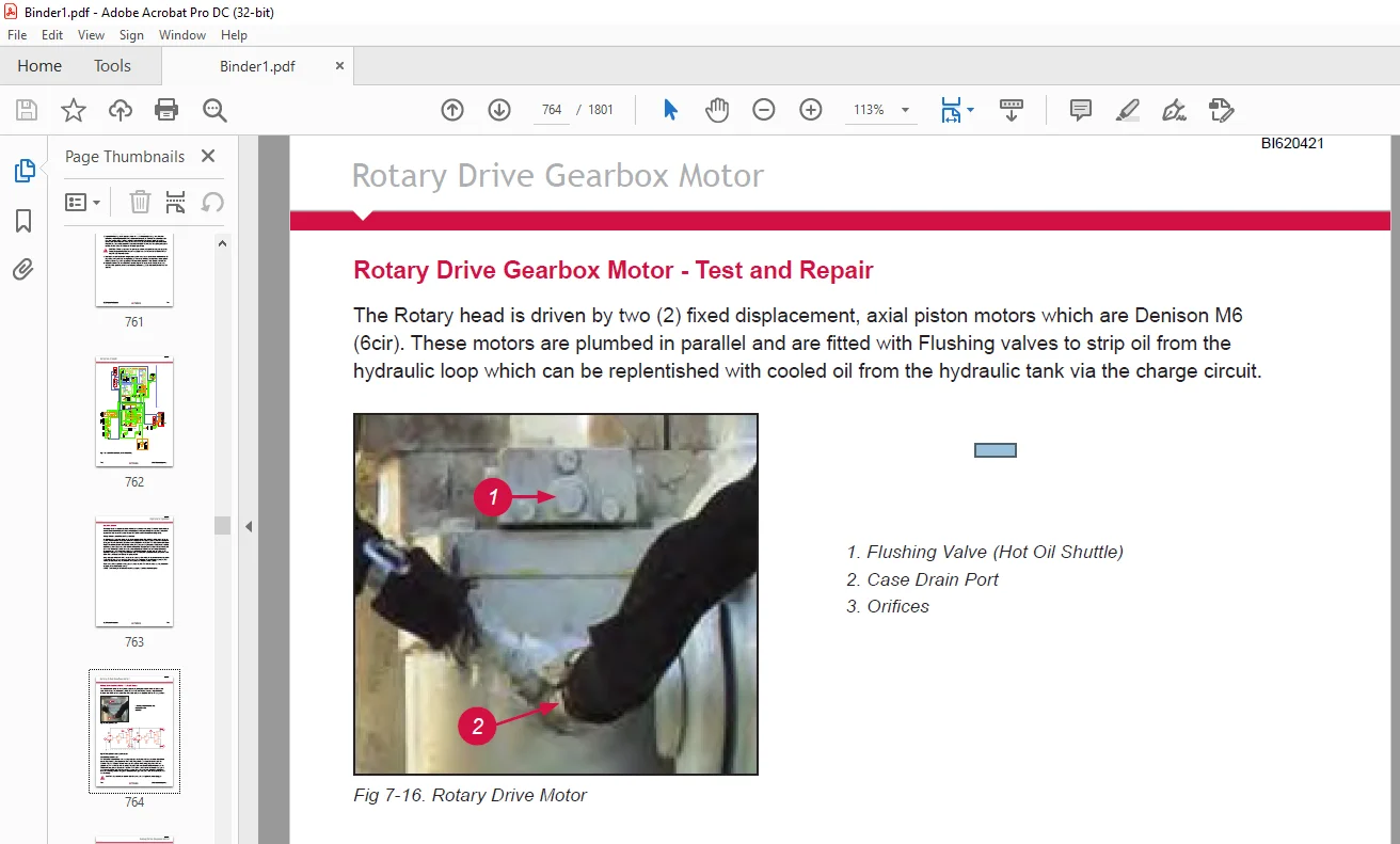
Rotary Drive Gearbox Motor 7-44
Rotary Drive Gearbox Motor – Test and Repair 7-44
Shaft Seal Replacement 7-45
Trouvle Shooting 7-47
Tram Circuit 7-49
Tram Circuit 7-49
Feed and Auxiliary Pump Circuit 7-51
Hydraulic Piston Pumps – Removal and Replacement 7-51
Feed and Auxiliary Functions Pump 7-54
Repair Instructions 7-55
Pump Replacement – Start Up 7-56
Hydraulic Systems 7-58
Auxiliary and Feed Circuits 7-58
Main Control Valves 7-59
Valve Stand Assembly 7-59
MP18 Valve – Jack and Mast Raise Valve 7-60
MP22 Valve – Hoist and Pulldown Control 7-62
4WE6 – Aux Functions and Mast Valves 7-65
Repair Kits 7-67
Exploded View of 4WE6 7-68
Counterbalance Valves 7-69
Counterbalance Valve Adjustment 7-69
BI620421
SKSS Introduction xv
Contents
Pilot Control Manifold 7-70
Control Valve Assembly 7-72
Auxiliary Pump Load Solenoid Valve 7-72
Hydraulic Feed Circuit 7-78
Feed Valve Assembly 7-83
Jack Control and Mast Elevating Circuit 7-87
Jack Control and Mast Elevating Circuit 7-88
Leveling Jack Cylinders 7-89
Counterbalance Valve Test Procedure 7-90
Mast Elevating Cylinders 7-91
Counterbalance Valve Test Procedure 7-92
Auxiliary Functions Circuit 7-93
Auxiliary Functions Circuit 7-93
Hydraulic Operated Breakout Wrench 7-95
Setting of HOBO Sequence Valves 7-96
Cooler Fan Circuit 7-102
Fan Motor Circuit 7-102
Cooler Fan Motor 7-105
Hydraulic Motor 7-105
Hydraulic Thermostatic Valve 7-109
Hydraulic Cooler – Thermal Valve 7-109
Central Lube 7-110
Hydraulic Circuit 7-111
Air Conditioner Compressor Drive Circuit 7-112
Air Conditioner Drive Motor 7-113
Design 7-113
Operational Check 7-113
Shaft Seal Replacement 7-114
Screw Tightening Torque 7-114
Gear Backlash 7-114
Specifications 7-114
Parts List 7-115
Water Injection / Foam Injection Circuit 7-116
Water Injection / Foam Injection Valve 7-117
Water Injection / Foam Injection Valve 7-119
Introduciton 7-119
Valve Stack Assembly 7-120
Segment Alterations 7-121
Pulsar Solenoid Removal and Plug 7-123
Recommended Test Stand 7-124
Final Stack Adjustment 7-127
Assembly Drawing – VBL Bypass Inlet Segment Parts List 7-133
Assembly Drawing – VPL Work Segment Parts List 7-135
Water Pump Motor 7-137
BI620421
xvi SKSS Introduction
Contents
Water Pump Motor Repair Information 7-137
Shaft Seal Repair 7-138
Foam Injection Unit 7-141
Hydraulic Cylinder Repair 7-142
General Information 7-143
H Head 7-145
N Head 7-146
Z Head 7-147
Z Head ( Two Piece) 7-148
K Head 7-149
M Head 7-150
Z Piston 7-151
Z Piston (Threaded) 7-152
H & K Piston 7-153
M Piston 7-154
N Piston 7-157
Section 8 – Electrical Components 8-1
Section 8 Contents 8-3
Electrical Locator 8-4
Electrical Locator Parts List 8-6
Jump Starting 8-7
Batteries 8-9
Welding Precautions 8-10
Vigilante Guide 8-11
Important Information 8-11
PLC 8-12
EEPROM 8-13
Output Card 8-14
Touchscreen 8-15
Laser Depth System 8-16
Safety Instructions & Precautions 8-17
Pipe in Hole Detection 8-18
Distance Meter 8-18
Start Up and Shut Down 8-19
Hydraulic Function Enable 8-19
Alarms 8-19
Solenoid Control 8-20
Auto Lube 8-23
Hammer Oiler System 8-23
Gauges 8-24
Pressure Transducer 8-24
Level Transducer 8-24
Hammer Oil Level Transducer 8-24
BI620421
SKSS Introduction xvii
Contents
Temperature Transducer 8-25
Water Flow Transducer 8-27
Inclinometers 8-28
Head Speed Module 8-29
Level Switches 8-30
Dust Suppression 8-30
Turkey Spray 8-30
Water Suppression Tank – Top Up 8-30
Vigilante System Component Information 8-31
Head Speed Module 8-31
Inclinometer 8-33
Ladder Prox Switch 8-36
LDM 40 A Laser 8-37
Level Switches – Capacitive Level Switch (Hydraulic Oil Level) 8-49
Radiator Level Switch 8-53
Level Transducer – Electronic Level Sensor 8-57
Hammer Oil Level Transducer 8-67
Pressure Transducer – Combined Pressure Sensor 8-69
Temperature Transducer – Control Monitor for Temperature Sensors 8-78
Temperature Sensor 8-90
Water Flow Transducer – Flow Sensor Analog 8-91
Water Control Module 8-105
Rod Counter Switch 8-134
Remote Fuel Level Display 8-135
Section 9 – Lubrication and Preventive Maintenance 9-1
Section 9 Contents 9-3
Central Lube System 9-5
Hydraulic Control Schematic 9-6
Auto Lube 9-6
Central Lube Pump Module 9-10
Central Lube Pump 9-23
Hammer Oiler Tank Assembly 9-49
Hammer Oil Circuit 9-50
Hammer Oil System 9-51
Air Service Unit Components 9-51
Filter Regulator 9-52
Air Line Oiler 9-53
Fire Ball 425 Pump – Instructions 9-54
Pipe Thread Lubricator 9-71
Air Service Unit 9-71
Filter Regulator 9-72
Air Line Lubricator 9-73
Pipe Thread Pump 9-74
BI620421
xviii SKSS Introduction
Contents
Filter Locator 9-82
Lubrication General 9-84
Equipment Lubrication 9-84
Care of Lubrication Points 9-84
Lubrication and Preventive Maintenance 9-85
Safety 9-85
Track Gear 9-85
Engine Maintenance 9-87
Air Cleaners 9-88
Air Filter Elements 9-88
Alternator Maintenance 9-88
Pump Drive and Drive Shaft Maintenance 9-89
Compressor Maintenance 9-89
Cooler Packs 9-89
A-Frame and Pivot Point Maintenance 9-91
Pull Down and Hoist Ropes and Sheaves Maintenance 9-91
Hydraulic System Maintenance 9-93
Hydraulic Maintenance 9-93
Water Pump Maintenance 9-93
Cab Maintenance 9-93
Air Conditioner Maintenance 9-95
Battery Maintenance 9-95
Lubrication System Maintenance 9-95
Fire Suppression Maintenance 9-95
Lubrication and Maintenance Chart 250hr 9-97
Lubrication and Maintenance Chart 500hr 9-107
Lubrication and Maintenance Chart 1000hr 9-118
Lubrication and Maintenance Chart 2000hr 9-129
Lubricant Specifications 9-141
Hydraulic System 9-141
Hydraulic Tank Capacity 9-141
Compressor Lubrication 9-142
Compressor Lubricant Specifications 9-142
Lubricating Grease 9-143
Gear Lubricant 9-143
Scheduled Oil Sampling Analysis 9-143
Torque Valves for Split Flange Connections 9-144
Customer Support: [email protected]
PLEASE NOTE:
- This is the same manual used by the dealers to diagnose and troubleshoot your vehicle
- You will be directed to the download page as soon as the purchase is completed. The whole payment and downloading process will take anywhere between 2-5 minutes
- Need any other service / repair / parts manual, please feel free to contact [email protected] . We still have 50,000 manuals unlisted
S.V