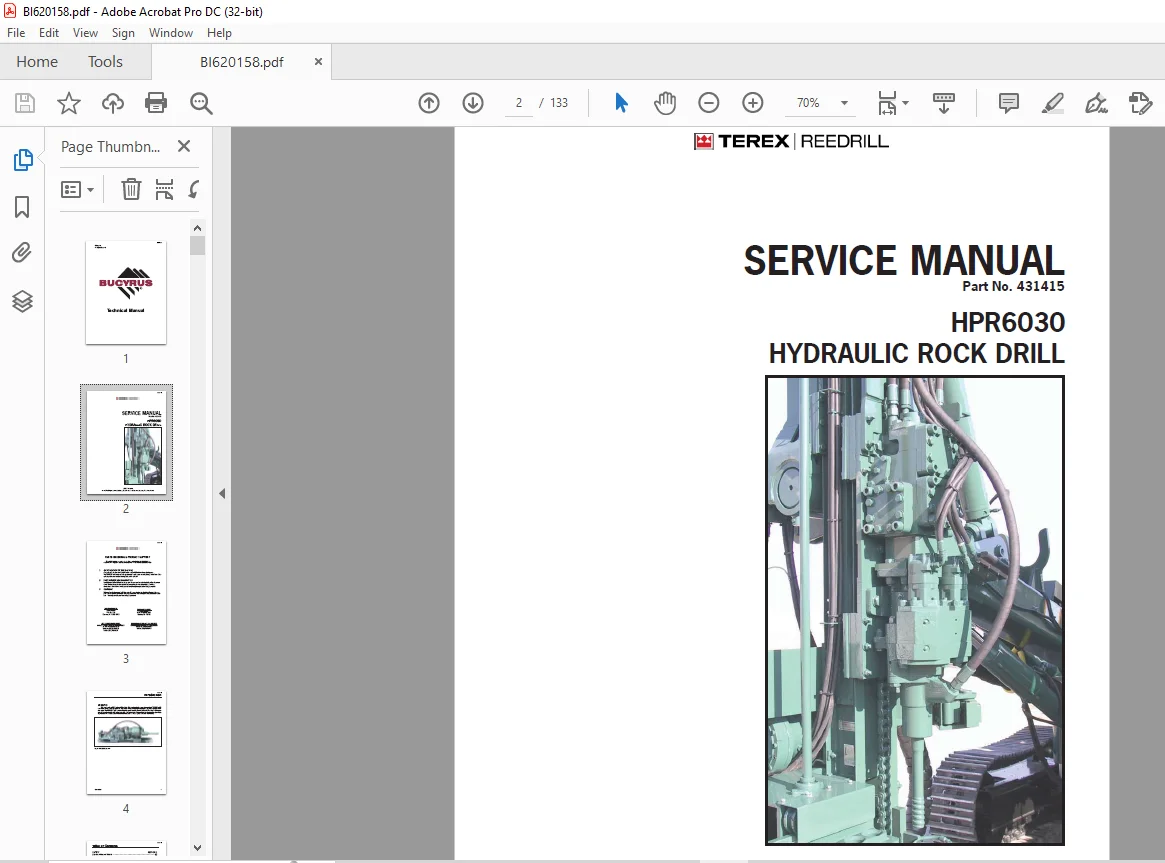
CAT Bucyrus TEREX REEDRILL HPR6030 HYDRAULIC ROCK DRILL SERVICE MANUAL 431415 – PDF DOWNLOAD
$28.95
CAT Bucyrus TEREX REEDRILL HPR6030 HYDRAULIC ROCK DRILL SERVICE MANUAL 431415 – PDF DOWNLOAD
Description
CAT Bucyrus TEREX REEDRILL HPR6030 HYDRAULIC ROCK DRILL SERVICE MANUAL 431415 – PDF DOWNLOAD
FILE DETAILS:
CAT Bucyrus TEREX REEDRILL HPR6030 HYDRAULIC ROCK DRILL SERVICE MANUAL 431415 – PDF DOWNLOAD
Language : English
Pages :133
Downloadable : Yes
File Type : PDF
DESCRIPTION:
CAT Bucyrus TEREX REEDRILL HPR6030 HYDRAULIC ROCK DRILL SERVICE MANUAL 431415 – PDF DOWNLOAD
Overview of Potential Hazards
The Hydraulic Rock Drill is used in conjunction with the Track Drill,a heavy moving machine with a boom capable of extending its reach vertically and horizontally. Like all moving objects and reach extending devices, there are potential hazards associated with its use. These hazards will be minimized if the machine is properly inspected and maintained. The operators should read this manual and have been trained to use the machine in an appropriate and safe manner. Should any questions arise concerning the maintenance or operation of the machine contact TEREX Reedrill at 1-800-258- 0009
Before Operation
• Do notify the owner of overhead or underground power lines before drilling. Be sure to comply with
all local regulations regarding safe operating distances from power lines. See table 1-1 for general
guidelines for safe distances from high voltage lines.
• Do study this manual and fully understand the controls.
• Do be sure all safety guards are securely in place.
• Do wear safety helmet, glasses and hearing protection when operating or working on machine.
• Do be sure all personnel are clear of the machine and work area before starting the engine or
operating machine.
• Do be sure drill area is clear of all obstructions before operating machine.
• Do attach safety chain when using towbar.
• Do Not operate machine with:
• Hydraulic or air leaks
• Broken or damaged electrical wiring or components
• Damaged hydraulic hoses or fittings
• Worn or damaged parts
Operation
• Do examine the surface before drilling to determine the possible presence of unfired explosives.
• Do provide sufficient ventilation when running the engine in an enclosed area. Exhaust gasses contain
carbon monoxide, a deadly poison, which is colorless and odorless.
• Do keep work areas clean and clear of cuttings, hand tools and other objects.
• Do place feed in horizontal position with feed resting on feed rest (if equipped) when tramming over
rough ground or during long moves. When moving from hole to hole, be sure feed is high enough to
clear ground obstacles. If feed hits something while tramming, feed can fall causing serious injury
or death.
• Do Not use the machine for any other purpose than what it was designed for. This machine is designed
for blasthole drilling operations only.
• Do Not wear jewelry or loose fitting clothing when working on machinery. Keep clothing and hands
clear of moving parts.
• Do Not travel on steep inclines, soft or unstable ground or close to unsupported excavations.
• Do Not move boom or machine if it is in a potentially unstable position.
• Do Not stand directly under a boom or feed.
• Do Not drill into or near a “bootleg” hole or any hole that may contain explosives.
After Operation
• Follow Shut Down Procedures as listed in Operator’s Manual.
Maintenance
• Do have two people present when performing service work, both being fully trained on the safety
issues. One person shall supervise from the operator’s position and have immediate access to an
emergency stop in all situations. Visual, audible or verbal communication signals must be established
and understood by both persons.
• Do make sure each person is adequately trained to perform service and maintenance procedures.
• Do place a warning tag on starting controls to alert personnel that someone is working on the
machine and disconnect battery before making repairs or adjustments to machine.
• Do have adequate lighting when performing service work at night.
• Do relieve pressure on hydraulic or pneumatic systems before loosening connections or parts.
• Do make sure machine and components are well supported before servicing or replacing parts.
• Do maintain a metal-to-metal contact between the fill nozzle and fuel tank when filling the fuel tank.
This will prevent sparks and the possibility of an explosion.
• Do make sure no tools or other loose objects are left on the engine or drive mechanisms. They
could be thrown by this equipment with a powerful force.
• Do Not service or perform maintenance while machine is running.
• Do Not smoke or use an open flame near batteries, when servicing the batteries. Batteries can give
off hydrogen which is a highly explosive gas.
• Do Not hammer bit or drill steel. Use only proper tools to make repair or adjustments.
• Do Not weld or grind near oil lines.
• Do Not attempt to remove radiator cap when engine is hot or has overheated.
IMAGES PREVIEW OF THE MANUAL:
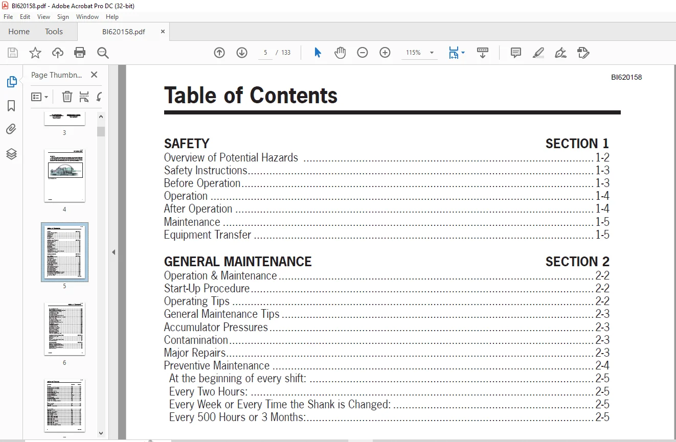
TABLE OF CONTENTS:
CAT Bucyrus TEREX REEDRILL HPR6030 HYDRAULIC ROCK DRILL SERVICE MANUAL 431415 – PDF DOWNLOAD
SAFETY SECTION 1
Overview of Potential Hazards 1-2
Safety Instructions 1-3
Before Operation 1-3
Operation 1-4
After Operation 1-4
Maintenance 1-5
Equipment Transfer 1-5
GENERAL MAINTENANCE SECTION 2
Operation & Maintenance 2-2
Start-Up Procedure 2-2
Operating Tips 2-2
General Maintenance Tips 2-3
Accumulator Pressures 2-3
Contamination 2-3
Major Repairs 2-3
Preventive Maintenance 2-4
At the beginning of every shift: 2-5
Every Two Hours: 2-5
Every Week or Every Time the Shank is Changed: 2-5
Every 500 Hours or 3 Months: 2-5
TROUBLESHOOTING SECTION 3
DRILL REPAIR SECTION 4
General Tips on Drill Overhaul 4-2
Tool Requirements 4-3
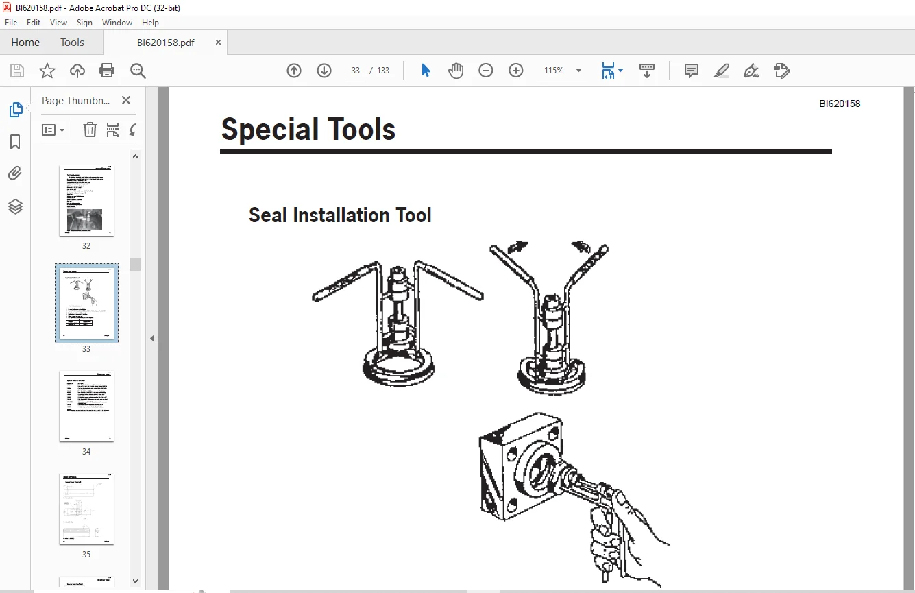
Seal Installation Tool 4-4
Special Tool List (Optional) 4-5
Special Tools (Optional) 4-6
Drill Torque Specifications 4-9
Removal of Drill from the Feed 4-10
Installation of Drill on the Feed 4-12
Drill Disassembly 4-14
General Information 4-15
Water Swivel Assembly – Removal 4-15
Water Swivel Housing – Repair 4-16
Rotation Motors – Removal 4-17
Rotation Housing – Removal 4-18
Rotation Cover – Removal 4-19
Rotation Housing – Internal Parts 4-20
Chuck Driver & Pinion Gears – Removal & Inspection 4-21
Chuck Driver Bearing Plate – Removal & Inspection 4-22
Thrust Washer – Inspection 4-23
Cylinder – Internal Parts 4-24
BI620158
Introduction iii
Table of Contents
Cylinder – Component Parts 4-25
Backhead – Removal and Inspection 4-25
Hammer and Bushings – Removal and Inspection 4-25
Shuttle Valve – Removal and Inspection 4-28
Shuttle Valve – Internal Parts 4-30
Accumulator – Internal Parts 4-34
Accumulators – Removal 4-35
Accumulators – Disassembly and Inspection 4-36
Cylinder – Internal Parts 4-38
Rear Cylinder Bushing and Backhead – Installation 4-39
Hammer – Installation 4-42
Cylinder – Internal Parts 4-44
Front Cylinder Bushing – Installation 4-45
Accumulator – Internal Parts 4-48
Accumulators – Assembly and Installation 4-48
Drill Assembly 4-52
Shuttle Valve – Internal Parts 4-52
Shuttle Valve – Assembly 4-53
Shuttle Valve – Installation 4-56
Shuttle Valve – Internal Parts 4-58
Rotation Housing – Internal Parts 4-62
Rotation Housing – Assembly 4-63
Chuck Driver – Assembly 4-67
Rotation Housing – Assembly 4-68
Rotation Motors – Installation 4-72
Water Swivel – Assembly 4-74
Water Swivel and Shank – Installation 4-78
CHARGING THE ACCUMULATORS SECTION 5
Charging the Accumulators 5-2
Requirements 5-2
Procedure 5-3
Checking the Accumulator Charge Pressure 5-4
Accumulator Charge Kit 5-7
SPECIFICATIONS SECTION 6
Hydraulic Oils for Percussion Drills 6-2
Hydraulic Drill Rotation Unit Lubrication 6-3
Grease Lubrication with a Hand Grease Gun 6-3
Grease Specifications 6-3
HPR6030 Wear Tolerances (60mm shank) 6-4
Maintenance Record 6-9
BI620158
iv Introduction
Index to Figures
A
Accumulator 4-54 4-50
Accumulator Assembly – Cross Section 4-32 4-34
Accumulator Assembly – Cross Section 4-51 4-48
Accumulator Bolts 4-52 4-49
Accumulator Bolts 4-55 4-50
Accumulator Bolts – Final Torque 4-57 4-51
Accumulator Charge Valve 4-53 4-49
Accumulator Charge Valve and O Ring 4-34 4-36
Accumulator Charging Set-up 5-1 5-2
Accumulator Diaphragm 4-35 4-36
Accumulator Diaphragm Damage 4-36, 4-37 4-37
Accumulators 4-33 4-35
Accumulators Installed 4-56 4-51
Adapter (1421459-01) see also Tools 4-9 4-8
Adapter Covers Installation 4-88 4-71
Automatic Valve – Installation 4-59 4-53
Automatic Valve – showing signs of cavitation 4-31 4-33
B
Backhead – Installation 4-44 4-42
Back-pressure Valve 5-2 5-5
Bearing Plate 4-23 4-22
Bearing Plate – O Ring Installation 4-77 4-65
C
Cap – see also Tools 4-3 4-6
Charge Gauge Assembly 5-3 5-6
Chuck Driver 4-79 4-67
Chuck Driver – Chuck Installation 4-81 4-67
Chuck Driver – Installing Chuck 4-80 4-67
Chuck Driver Bushing 4-76 4-65
Chuck Driver Bushing Installation 4-78 4-66
Cylinder – Rear View 4-41 4-40
Cylinder Assembly – Cross Section 4-24 4-24
Cylinder Assembly – Cross Section 4-38 4-38
Cylinder Assembly – Cross Section 4-38 4-44
Cylinder Bushing – Front 4-47 4-45
Cylinder Bushing – Front 4-48 4-46
Cylinder Bushing, Front – Installation 4-49 4-46
Cylinder Bushing, Front – Installation 4-50 4-47
Cylinder Bushing – Rear 4-39 4-39
Cylinder Bushing – Rear 4-39 4-40
Cylinder Bushing, Rear – Installation 4-42, 4-43 4-41
Cylinder Bushing showing signs of cavitation 4-26 4-26
D
Driver (1414948) see also Tools 4-2 4-6
Driver (1421457) see also Tools 4-5 4-7
Dust Cap – Left Side 4-28 4-29
Dust Cap – Right Side 4-27 4-28
G
Grease and Relief Fittings Location 2-1 2-4
H
Hammer (1421460) – see also Tools 4-10 4-8
Hammer 4-45 4-43
Hammer – Installation 4-46 4-43
Hammer showing normal wear 4-25 4-26
Hex Bar (1413170) see also Tools 4-4 4-6
Hex Bar (1416210) see also Tools 4-7 4-7
HPR6030 Rock Drill i-1 i
HPR6030 Major Components 4-14 4-14
I
Insert Set (428815) see also Tools 4-6 4-7
M
Mounting Slide 4-12 4-10
Mounting Slide 4-13 4-12
P
Pinion Gear Roller Bearings 4-72, 4-73 4-63
Pinion Gear Seal Installation 4-86, 4-87 4-70
Pinion Gears 4-22 4-21
Puller (1421459) see also Tools 4-8 4-8
R
Retainer Plug – Installation 4-62 4-55
Retainer Plug and Retaining Ring – Right Side 4-30 4-31
Rotation Cover – Dowel Pin Installation 4-74 4-64
Rotation Cover – Installation 4-84, 4-85 4-69
Rotation Cover – Removal 4-19, 4-20 4-19
Rotation Housing – Greasing 4-82 4-68
Rotation Housing – Removal 4-18 4-18
Rotation Housing – Vent Plug Installation 4-75 4-64
Rotation Housing Assembly – Cross Section 4-21 4-20
Rotation Housing Assembly – Cross Section 4-71 4-62
Rotation Housing to Cylinder Installation 4-89 4-71
Rotation Housing with pinion gears and chuck driver installed 4-83 4-68
Rotation Motor to Adapter Plate Installation 4-90 4-72
BI620158
vi Introduction
Index to Figures
Description Figure No Page No
Rotation Motors – Checking Clearance 4-91 4-73
Rotation Motors – Removal 4-17 4-17
Rotation Motors Installation 4-92 4-73
S
Seal Installation Tool – see also Tools 4-1a 4-4
Shank Installation 4-99 4-78
Shuttle Valve – Cross Section 4-29 4-30
Shuttle Valve – Cross Section 4-29 4-32
Shuttle Valve – Cross Section 4-58 4-58
Shuttle Valve – R H Dust Cap Installation 4-70 4-59
Shuttle Valve – Retaining Ring Installation 4-69 4-59
Shuttle Valve Assembly 4-65 4-56
Shuttle Valve Bore 4-63 4-55
Shuttle Valve Bore 4-64 4-56
Shuttle Valve Installation 4-66, 4-67, 4-68 4-57
T
Thrust Washer – showing 030″ wear 4-23a 4-23
Tools required for drill repair 4-1 4-3
Tools – Special 4-6
Adapter (1421459-01) 4-9 4-8
Cap 4-3 4-6
Driver (1414948) 4-2 4-6
Driver (1421457) 4-5 4-7
Hammer (1421460) 4-10 4-8
Hex Bar (1413170) 4-4 4-6
Hex Bar (1416210) 4-7 4-7
Insert Set (428815) 4-6 4-7
Puller (1421459) 4-8 4-8
Seal Installation Tool 4-1a 4-4
Torque Specifications for HPR6030 Drill 4-11 4-9
V
Valve Seat – Installation 4-60, 4-61 4-54
W
Water Swivel Bushing – Rear Seal Installation 4-96 4-76
Water Swivel Housing – Seal Installation 4-94 4-75
Water Swivel Housing Removal 4-15 4-15
Water Swivel Housing with seals installed 4-95 4-75
Water Swivel Housing Retaining Ring Installation 4-97 4-77
Water Swivel Housing Rod Wiper Installation 4-98 4-77
Water Swivel Installation 4-100 4-79
Water Swivel Internal Parts 4-16 4-16
Water Swivel Internal Parts – Cross Section 4-93 4-74
Need help? Contact: [email protected]
https://vimeo.com/864761846?share=copy
PLEASE NOTE:
- This is the SAME exact manual used by your dealers to fix your vehicle.
- The same can be yours in the next 2-3 mins as you will be directed to the download page immediately after paying for the manual.
- Any queries / doubts regarding your purchase, please feel free to contact [email protected]
S.M