CAT Continuous Haulage FH330 PARTS Manual – PDF DOWNLOAD
Original price was: $78.00.$26.95Current price is: $26.95.
CAT Continuous Haulage FH330 PARTS Manual – PDF DOWNLOAD
FHY01706
Description
CAT Continuous Haulage FH330 PARTS Manual – PDF DOWNLOAD
FILE DETAILS:
CAT Continuous Haulage FH330 PARTS Manual – PDF DOWNLOAD
Language : English
Pages :401
Downloadable : Yes
File Type : PDF
Size:7.82 MB
FHY01706
DESCRIPTION:
CAT Continuous Haulage FH330 PARTS Manual – PDF DOWNLOAD
1. MACHINE IDENTIFICATION
Cat machines are identified by Product Identification Numbers (PIN). Some components included in a machine may be identified by Serial Numbers (S/N). Typical components that will be serialized include engines, transmissions, bulldozers, and rippers. The machine and engine are further identified by arrangement numbers and in some cases modification numbers. These numbers are shown on the product identification plate(s) and on the master plate in the operator’s compartment. Cat dealers need all of these numbers to determine accurate parts identification. Effective First Quarter 2001 the Cat Product Identification Number (PIN) changed from 8 to 17 characters. In an effort to provide uniform equipment identification, Caterpillar and other construction equipment manufacturers are moving to comply with the latest version of the product identification numbering standard. Non-road machine PINs are defined by ISO 10261. The new PIN format will apply to all Cat machines and generator sets. The PIN plates and frame marking will display the 17 character PIN. The new format will look like the following:
Where:
(1) – Caterpillar’s World Manufacturing Code (characters
1- 3)
(2) – Machine Descriptor (characters 4-8)
(3) – Check Character (character 9)
(4) – Machine Indicator Section (MIS) or Product
Sequence Number (characters 10-17). These were
previously referred to as the Serial Number.
Machines and generator sets produced before First Quarter 2001 will maintain their 8 character PIN format. Components such as engines, transmissions, axles, etc. and work tools will continue to use an 8 character Serial Number (S/N).
2. ORDERING PARTS
When replacement parts are required for this product, Caterpillar recommends using Cat re placement parts or parts with equivalent specifi cations including, but not limited to, physical dimensions, type, strength and material Failure to heed this warning can lead to prema ture failures, product damage, personal injury or death.
Quality Cat replacement parts are available from Cat dealers throughout the world. Their parts inventories are up to date and include all parts normally required to protect your investment in Cat machines. Dealers may offer repair kits or remanufactured parts to allow selection of the most effective repair alternative for a particular situation. When ordering parts, your order should specify the quantity, part number, part name, and the serial number/product identification number of the machine for which the parts are needed
3. PARTS MANUAL ORGANIZATION
Product information in this manual is presented as “information elements” that represent all of the components for the specific model. Engine Arrangement and Seat Group are examples of information elements. The information elements are organized alphabetically by part name and secondarily by part number within each major section of the manual
4. TABLE OF CONTENTS
A table of contents (TOC) is found at the beginning of the manual. The TOC lists each section of the manual with a complete list of all information elements organized as they appear in the manual. Page numbers are provided for quick reference to detailed parts identification illustrations and serviceable consist lists
5. INDEX
The index located near the front of the manual is an alphabetical listing of all information elements included in the manual. Page numbers are provided for quick reference to detailed parts identification illustrations and serviceable consist lists.
7. CAPTIONS
Captions located at the beginning of each information element identify the part number and part name. PIN and S/N information found in each caption should be used to select correct information for a specific machine. Field replacement options, identification of optional attachment components, and where used (“part of”) information is also provided. The first line of a caption is shown in larger type font to indicate the beginning of an information element. Captions for additional pages that may be required to illustrate an information element will be shown in standard type font and will include the term (contd.).
8. NON-SERVICE
PARTS In some instances it is necessary to display non-serviced parts that are a link to a lower level serviceable consist lists. These non-serviced part numbers are shown in italic type indicating that they are not available
9. PARTS LIST REFERENCE NUMBERS
Numbers shown in the Ref No column correspond to numbers used in the associated graphic(s). An alphabetic suffix may be added to a reference number to identify lower level consist items. Numbers shown in the Graphic Ref column refer to the graphic number identifier displayed in the lower left corner of each illustration. The Graphic Ref number may be used in combination with the item Ref No to determine the correct part number. There may be intentional omission of a Ref No in a consist list as information is updated to reflect the latest serviceable part numbers
10. <END>
This symbol indicates the end of an information element. Note: – Continuing improvement and advancement of product design may cause changes to your machine which may not be included in this publication. Whenever a question arises regarding your Cat product or this publication, please consult your Cat dealer for the latest available information
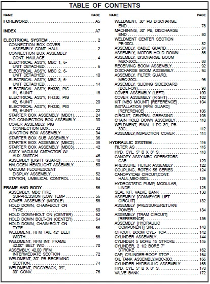
TABLE OF CONTENTS:
CAT Continuous Haulage FH330 PARTS Manual – PDF DOWNLOAD
FOREWORD ........................................  9
INDEX ........................................... 11
ELECTRICAL SYSTEM ............................... 16
	CONNECTION BOX COVER ASSEMBLY CONT. HAUL .... 16
	CONNECTION BOX ASSEMBLY CONT. HAULAGE ....... 18
	ELECTRICAL ASS'Y, MBC 1, 6-UNIT DETACHED .... 20
	ELECTRICAL ASS'Y, MBC 2, 6-UNIT DETACHED .... 24
	ELECTRICAL ASS'Y, MBC 3, 6-UNIT DETACHED .... 28
	ELECTRICAL ASS'Y, FH330, PIG #1, 6-UNIT ..... 32
	ELECTRICAL ASS'Y, FH330, PIG #2, 6-UNIT ..... 34
	ELECTRICAL ASS'Y, FH330, PIG #3, 6-UNIT ..... 36
	STARTER BOX ASSEMBLY (MBC1) ................. 38
	PIG CONNECTION BOX ASSEMBLY ................. 44
	COVER ASSEMBLY, PIG CONNECTION BOX .......... 46
	JUNCTION BOX ASSEMBLY ....................... 48
	STARTER BOX SUB ASSEMBLY .................... 50
	STARTER BOX ASSEMBLY (MBC2) ................. 52
	STARTER BOX ASSEMBLY (MBC3) ................. 56
	ASS'Y VACUUM CNTACTOR W/ AUX SWITCH ......... 60
	ASSEMBLY [LIGHT GUARD] ...................... 62
	HALOGEN HEADLIGHT ASSEMBLY .................. 64
	VACUUM FLOURESCENT DISPLAY ASSEMBLY ......... 66
	STATION, UMBILICAL CONTROL .................. 68
FRAME AND BODY .................................. 70
	ASSEMBLY, MBC FIRE SUPPRESSION (LOW TEMP .... 70
	COVER ASSEMBLY (MIDDLE) ..................... 72
	HOLD DOWN, CHAIN-BOLT ON TYPE ............... 74
	HOLD DOWN-BOLT ON (CENTER) .................. 76
	HOLD DOWN BOLT-ON (CENTER) .................. 78
	HOLD DOWN, CHAIN-BOLT ON TYPE ............... 80
	WELDMENT, RFM TAIL 42" BELT WIDTH ........... 82
	WELDMENT, RFM INT. FRAME 42.00" BELT WID .... 84
	ASSEMBLY, 42.00 RFM INTERMEDIATE SECTION .... 86
	WELDMENT, 30" PB RECEIVING SECTION .......... 88
	WELDMENT, PIGGYBACK, 39", 30" CONV. ......... 90
	WELDMENT, 30" PB DISCHARGE END .............. 92
	MACHINING, 30" PB, DISCHARGE END ............ 94
	WELDMENT CENTER SECTION PB-30CL ............. 96
	ASSEMBLY, CABLE GUARD ....................... 98
	ASSEMBLY, MOTOR HOLD DOWN ...................100
	ASSEMBLY, DISCHARGE BOOM MBC-30CL ...........102
	RECEIVING BOOM ASSEMBLY .....................106
	DISCHARGE BOOM ASSEMBLY .....................108
	ASSEMBLY, FILTER GUARD, MBC-30CL ............110
	ASSEMBLY, SLIDING SIDEBOARD (BOLT-ON) .......112
	COVER ASSEMBLY (LEFT) .......................114
	COVER ASSEMBLY (RIGHT) ......................116
	KIT [MBC MOUNT] [REFERENCE] .................118
	INSTALLATION [RFM GUARD] [REFERENCE] ........120
	CIRCUIT, CENTRAL GREASING ...................122
	CHAIN HOLD DOWN ASSEMBLY ....................124
	WELDMENT, FINAL 1 PC 39', PB-30CL ...........126
	ASSEMBLY,INSPECTION COVER ...................128
HYDRAULIC SYSTEM ................................130
	FILTER AS ...................................130
	HYD. CYL. 5" B X 8" S .......................132
	CANOPY ASSY-MBC OPERATORS CAB ...............134
	PRESSURE FILTER ASSEMBLY ....................136
	COUPLING, ROTEK 55 SERIES ...................138
	CANOPY/CAB CIRCUIT,CONT.HAUL,MBC-30CL .......140
	HYDROSTATIC PUMP, MODULAR, LINDE ............142
	SEAL KIT, VALVE BANK ........................144
	ASSEMBLY [CONVEYOR LIFT CIRCUIT] ............146
	ASSEMBLY [PRESSURE/RETURN/POWER .............148
	ASSEMBLY [TRAM CIRCUIT] [REFERENCE] .........150
	ASSEMBLY [HYDRAULIC COMPONENT] S/N ..........154
	CIRCUIT, BOOM CYL.- TOP .....................156
	CYLINDER ASSEMBLY ...........................158
	CYLINDER 5 BORE 15 STROKE ...................160
	CYLINDER 5 BORE 15 STROKE ...................162
	CYLINDER 5 BORE 15 STROKE ...................164
	CYLINDER 5 BORE 15 STROKE ...................166
	CYLINDER 5 BORE 15 STROKE ...................168
	CYLINDER 5 BORE 15 STROKE ...................170
	CYLINDER 5 BORE 15 STROKE ...................172
	CYLINDER 5 BORE 15 STROKE ...................174
	CYLINDER, 2 1/2 BORE 7" STROKE ..............176
	CAP, CYLINDER-ROOF STOP .....................178
	OIL TANK ASSEMBLY,MBC-30C ...................180
	CYLINDER HYDRAULIC ASSEMBLY .................182
	HYD. CYL. 5" B X 8" S .......................184
	VALVE BANK ..................................186
IMPLEMENTS ......................................188
	BRETBY CABLE HANDLER 190MX110M (5'SECT) .....188
	HANDLING CABLE ..............................190
	HANDLING CABLE ..............................192
	HANDLER CABLE ...............................194
	OFFSET BRACKET, BRETBY ......................196
MACHINE ARRANGEMENT .............................198
	ASSEMBLY, RFM TAIL SUPP. SECT - 42" BELT ....198
	ASSEMBLY, 39' PB-30CL MAIN ..................200
	ASSEMBLY [TAIL DOLLY] .......................204
MATERIAL HANDLING ...............................206
	ASSY, 2" PITCH HAULAGE CHAIN, 63 FLIGHTS ....206
	ASSY, 2" PITCH HAULAGE CHAIN, 40 FLIGHTS ....208
	TAIL SHAFT ASSEMBLY (W/ CAT SEALS) ..........210
	WHEEL ASS'Y W/ BEARINGS MBC DOLLY W/ ADJ ....212
	ROLLER ASS'Y W/ STEEL BUSHINGS MBC DOLLY ....214
	TAILSHAFT ASSEMBLY (W/CAT SEALS) ............216
	ROLLER ASSY, TAILSHAFT MBC & PB .............218
	ASSEMBLY, BELT WIPER 42" BELT TAILPIECE .....220
	ASSEMBLY, DOLLY, MBC ........................222
	ASSY, 2" PITCH HAULAGE CHAIN, 10 SECTION ....224
	ASSY PULLEY 12X44 4.94BRGS ..................226
	ASSY, 2" PITCH HAULAGE CHAIN, 63 FLIGHTS ....228
	BELT TRAINER ASSY 42BW ......................230
OPERATOR STATION ................................232
	SEAT ASSEMBLY ...............................232
	SEAT CUSHION ASSEMBLY .......................234
	DISPLAY MOUNTING BRACKET ASSEMBLY ...........236
	ARM REST FOR MBC ............................238
	FOOT SWITCH ASSEMBLY ........................240
	GAUGE PANEL ASSEMBLY ........................242
	OPERATORS CAB ASSEMBLY-MBC ..................244
POWER TRAIN .....................................246
	SHAFT/GEAR ASSEMBLY .........................246
	SHAFT/GEAR ASSEMBLY .........................248
	TRAM GEARCASE ASSEMBLY ......................250
	REDUCER ASSEMBLY ............................254
	DRIVE SHAFT ASSEMBLY ........................256
	RING GEAR ASSEMBLY ..........................258
	DRIVE SHAFT ASSEMBLY ........................260
	GUARD, REDUCER W/O CABLE LUGS ...............262
	REDUCER ASSEMBLY ............................264
	RING GEAR ASSEMBLY ..........................266
	ASSEMBLY, TORQUE LIMITER ....................268
SERVICE EQUIPMENT AND SUPPLIES ..................270
	KIT, WARNING PLATE ..........................270
TOP LEVEL ASSEMBLIES ............................272
	ELECTRICAL ASS'Y, MBC 1, 6-UNIT DETACHED ....272
	ELECTRICAL ASS'Y, MBC 2, 6-UNIT DETACHED ....276
	ELECTRICAL ASS'Y, MBC 3, 6-UNIT DETACHED ....280
	ELECTRICAL ASS'Y, FH330, PIG #1, 6-UNIT .....284
	ELECTRICAL ASS'Y, FH330, PIG #2, 6-UNIT .....286
	ELECTRICAL ASS'Y, FH330, PIG #3, 6-UNIT .....288
	ASSEMBLY, 42.00 RFM INTERMEDIATE SECTION ....290
UNCATEGORIZED LOWER LEVELS ......................292
	ASSEMBLY, MBC FIRE SUPPRESSION (LOW TEMP ....292
	ASSY, 2" PITCH HAULAGE CHAIN, 63 FLIGHTS ....294
	ASSY, 2" PITCH HAULAGE CHAIN, 40 FLIGHTS ....296
	INSTALLATION, MBC-30CL WEDGE CRAWLER ........298
	CONNECTION BOX COVER ASSEMBLY CONT. HAUL ....300
	CONNECTION BOX ASSEMBLY CONT. HAULAGE .......302
	STARTER BOX ASSEMBLY (MBC1) .................304
	PIG CONNECTION BOX ASSEMBLY .................310
	COVER ASSEMBLY (MIDDLE) .....................312
	COVER ASSEMBLY, PIG CONNECTION BOX ..........314
	JUNCTION BOX ASSEMBLY .......................316
	SEAT CUSHION ASSEMBLY .......................318
	RING GEAR ASSEMBLY ..........................320
	ASSEMBLY, 42.00 RFM INTERMEDIATE SECTION ....322
	MACHINING, 30" PB, DISCHARGE END ............324
	ASSEMBLY, DOLLY, MBC ........................326
	SEAL KIT, VALVE BANK ........................328
	STARTER BOX SUB ASSEMBLY ....................330
	ASSY, 2" PITCH HAULAGE CHAIN, 10 SECTION ....332
	COVER ASSEMBLY (RIGHT) ......................334
	ASS'Y VACUUM CNTACTOR W/ AUX SWITCH .........336
	ASSEMBLY [LIGHT GUARD] ......................338
	CYLINDER ASSEMBLY ...........................340
	CYLINDER 5 BORE 15 STROKE ...................342
	CYLINDER, 2 1/2 BORE 7" STROKE ..............344
	ARM REST FOR MBC ............................346
	CAP, CYLINDER-ROOF STOP .....................348
	CRAWLER TAKE UP IDLER ASSEMBLY ..............350
	CHAIN HOLD DOWN ASSEMBLY ....................352
	GUARD, REDUCER W/O CABLE LUGS ...............354
	KIT, WARNING PLATE ..........................356
	OFFSET BRACKET, BRETBY ......................358
	VACUUM FLOURESCENT DISPLAY ASSEMBLY .........360
	FOOT SWITCH ASSEMBLY ........................362
	GAUGE PANEL ASSEMBLY ........................364
	ASSEMBLY,INSPECTION COVER ...................366
	ASSEMBLY, TORQUE LIMITER ....................368
	CYLINDER HYDRAULIC ASSEMBLY .................370
	STATION, UMBILICAL CONTROL ..................372
UNDERCARRIAGE ...................................374
	INSTALLATION, MBC-30CL WEDGE CRAWLER ........374
	MECHANICAL ASSEMBLY, MBC-30CL WEDGE CRAW ....376
	GREASE TAKE UP ASSEMBLY (W/SHIMS) ...........382
	CRAWLER ASSEMBLY ............................384
	CRAWLER TAKE UP IDLER ASSEMBLY ..............386
PART NUMBER INDEX ...............................389
IMAGES PREVIEW OF THE MANUAL:
Customer Support: [email protected]
PLEASE NOTE:
- This is not a physical manual but a digital manual – meaning no physical copy will be couriered to you. The manual can be yours in the next 2 mins as once you make the payment, you will be directed to the download page IMMEDIATELY.
- This is the same manual used by the dealers inorder to diagnose your vehicle of its faults.
- Require some other service manual or have any queries: please WRITE to us at [email protected]