Trusted Business
Verified & Licensed
Virus Free Files
100% Safe Downloads
Secure Payment
SSL Protected
Instant Delivery
Available Immediately
Cat EL2000 Shearer Operating Manual – PDF DOWNLOAD
$28.95
Cat EL2000 Shearer Operating Manual – PDF DOWNLOAD
Instant PDF Download
Available immediately
Save to Your Device
Download & keep forever
Antivirus Scanned
100% virus-free
Trusted Worldwide
175,000+ customers
Description
Cat EL2000 Shearer Operating Manual – PDF DOWNLOAD
FILE DETAILS:
Cat EL2000 Shearer Operating Manual – PDF DOWNLOAD
Language : English
Pages : 339
Downloadable : Yes
File Type : PDF
IMAGES PREVIEW OF THE MANUAL:
DESCRIPTION:
Cat EL2000 Shearer Operating Manual – PDF DOWNLOAD
About this manual
This chapter contains important information which will simplify the
use of this manual for you. In addition it includes information about
the structure of the manual and on the characters and symbols
used.
This chapter contains important information which will simplify the
use of this manual for you. In addition it includes information about
the structure of the manual and on the characters and symbols
used.
Before starting work
correct operating manual
If you use an operating manual which has not been written for your machine type, you will endanger yourself and others. Ensure that the serial number on you machine corresponds with the following :
machine type
EL2000 Shearer
Ident. no.: EL2000-028 & 029
The operating manual must be accessible at all times to all persons
working on, or with, this shearer.
Ident. no.: EL2000-028 & 029
The operating manual must be accessible at all times to all persons
working on, or with, this shearer.
new operating manual
If your manual is no longer complete, has become illegible or damaged, send for a replacement immediately.
Who is this operating manual intended for?
This operating manual is intended for all persons working with or on
the shearer.
All persons working with the shearer must have read this manual.
This includes persons:
responsible for transport
carrying out the drivage
carrying out erection / dismantling
operating the shearer
eliminating faults
carrying out routine work on the face
carrying out maintenance operations
carrying out repairs
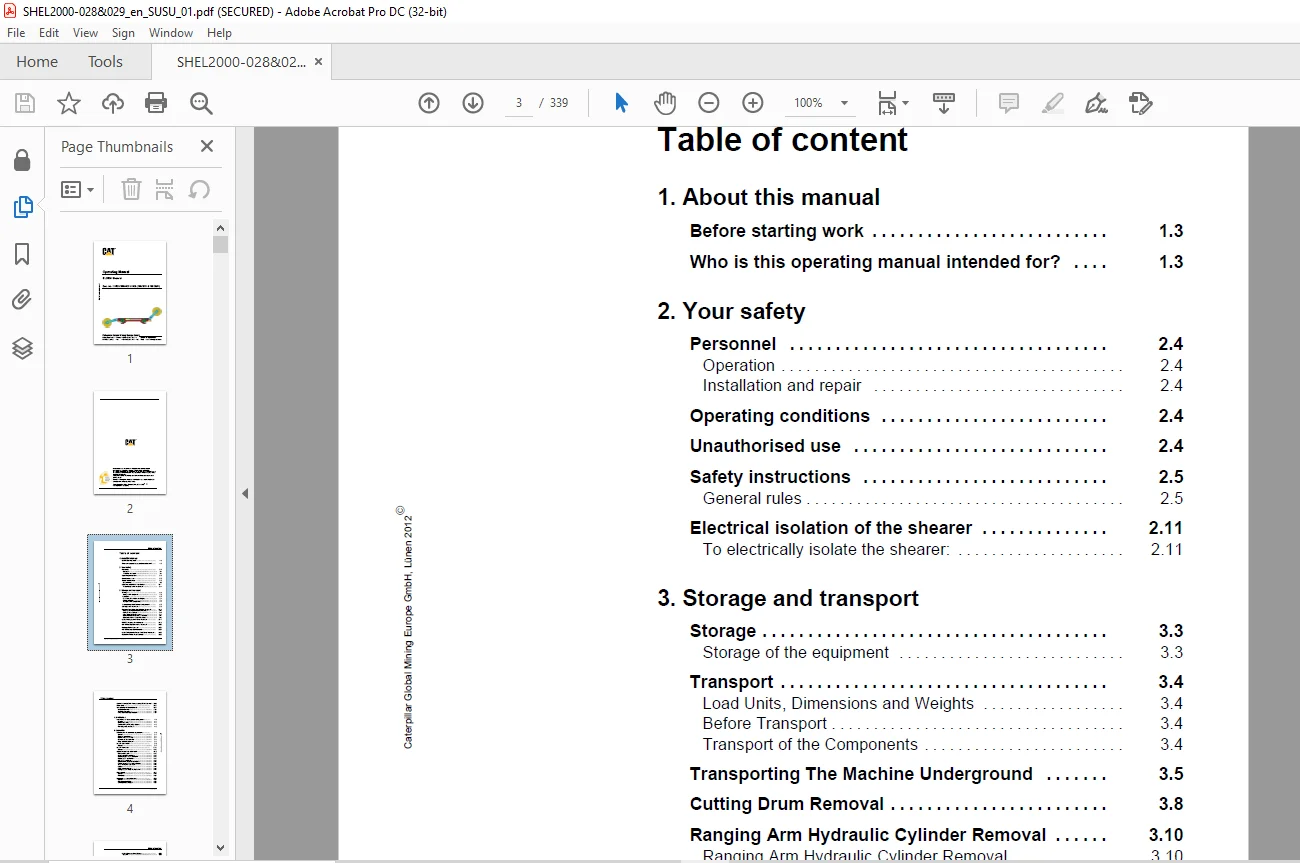
TABLE OF CONTENTS:
Cat EL2000 Shearer Operating Manual – PDF DOWNLOAD
EL2000-028 & 029 Electra 2000..........................................  1
	Contents...........................................................  3
	1. About this manual...............................................  9
		Before starting work........................................... 11
		Who is this operating manual for?.............................. 11
		Characters and symbols used.................................... 12
	2. Your safety..................................................... 13
		Your safety.................................................... 15
		Observe the safety & accident prevention rules................. 15
		Personnel...................................................... 16
		Operating conditions........................................... 16
		Unauthorised use............................................... 16
		Safety instructions............................................ 17
		Storage and transport.......................................... 18
		To electrically isolate the shearer............................ 23
	3. Storage and transport........................................... 25
		Storage........................................................ 27
		Transport...................................................... 28
		Unit weights................................................... 31
		Cutting drum removal........................................... 32
		Ranging arm hydraulic cylinder removal......................... 34
		EL68A Ranging arm motor removal................................ 41
		RA750 Ranging arm removal...................................... 42
		DD100 Haulage downdrive removal................................ 44
		Haulage motor removal.......................................... 46
		HU150 Haulage unit removal..................................... 47
		EL56BN Hydraulic power pack motor removal...................... 49
		Hydraulic power pack removal................................... 50
		EL49A Control box & EL48A power box removal.................... 52
		Mainframe...................................................... 54
		Shoepost/Skid shoe removal..................................... 56
	4. Installation.................................................... 61
		Installation of machine underground............................ 63
		Greasing....................................................... 64
		Oil and fluid filling.......................................... 64
		Commissioning the haulage system............................... 65
		Fault diagnosis and repair..................................... 66
	5. Operation....................................................... 67
		Introduction to electrical equipment........................... 69
			General.................................................... 69
			Electrical control boxes................................... 70
			Electric motor driven units................................ 70
			Hydraulic actuated units................................... 71
			Other electrical equipment................................. 71
			Electrical circuits........................................ 73
		EL49A Control box.............................................. 75
			General.................................................... 75
			Unit contents.............................................. 76
		EL48A Power box................................................ 79
			General.................................................... 79
			Component location......................................... 80
		Operator controls (electrical)................................. 81
			Main switch handle......................................... 83
			Machine 'START' pushbutton................................. 83
			Motors 'START' / 'STOP' pushbutton......................... 83
			Motor 'STOP' pushbutton.................................... 83
			AFC 'STOP' pushbutton...................................... 83
			Circuit earth leakage test pushbutton...................... 84
			Earth leakage circuits re-set pushbutton................... 84
			Stop/emergency stop lever.................................. 84
			Keypad..................................................... 84
			Radio control selection.................................... 84
			Haulage system circuit breaker handle...................... 84
		Electrical pilot circuit....................................... 85
			General.................................................... 85
			Pilot circuit.............................................. 86
		Electrical power distribution.................................. 89
			General.................................................... 89
			Main power distribution.................................... 90
			Control power distribution................................. 91
		EL68A Ranging arm motor........................................ 95
			General.................................................... 96
			System operation........................................... 97
			Motor start circuits....................................... 99
			Quill shaft removal procedures.............................100
			Lubrication................................................107
		EL56BN Hydraulic power pack motor..............................109
			General....................................................109
			System operation...........................................110
			Motor start circuit........................................111
			Lubrication................................................112
		Haulage motor..................................................113
			General....................................................113
			Motor operation............................................114
			Motor start circuit........................................114
			Motor removal procedure....................................114
			Quill shaft removal and assembly...........................117
			Lubrication................................................124
		Radio control system (Pempek)..................................125
			General....................................................125
			Transceiver................................................127
		Hydraulic functions (electric control).........................129
			General....................................................129
		Haulage system (AC drive)......................................133
			General description........................................133
			Basic system operation.....................................133
			AC Haulage drive(s)........................................134
			Configuration switches.....................................135
			Switch positions and modes.................................136
			Double drive operation.....................................137
			Parameters.................................................137
			Regeneration...............................................137
			Haulage circuit description................................137
			Monitoring circuits........................................138
			Radio control circuits.....................................139
			Transmitter control circuit................................139
		Component location (quick reference guide).....................141
			General....................................................141
			EL48A Left and right hand covers...........................142
			EL48A Component location...................................143
			EL49A Control cover........................................147
			Control compartment chassis................................149
		Maintenance (electrical).......................................151
			Maintenance schedules......................................152
		General machine specification..................................157
			Hoses......................................................159
			Abbreviations..............................................159
		Operator controls (mechanical & electrical)....................160
			Electrical supply..........................................160
			Machine controls...........................................160
			Control mode selector switch...............................160
			Cooling supply.............................................160
			Emergency stop switch and buttons..........................160
			Face conditions............................................161
			Stopping the shearer.......................................161
			Electrical trips...........................................161
			Shearer operators report...................................162
		Mainframe......................................................163
			Face side and plan.........................................164
			Waste side view............................................165
			Hinge pin arrangement......................................166
			Ranging arm cylinder anchor................................166
			Face side skid shoe........................................167
			Face side skid shoe wear limit.............................167
			Mainframe tie bar assembly procedure.......................168
			Ranging arm hinge points lubrication.......................173
		HU150 Haulage unit.............................................175
			General....................................................175
			Haulage system location....................................177
			General arrangement........................................178
			Brake......................................................179
			Encoder....................................................179
			Cooler arrangement.........................................180
			Oil level & temperature transducer.........................180
			Haulage unit lubrication...................................181
		DD100 Downdrive................................................182
			Downdrive system...........................................182
			Front and rear views.......................................183
			Component location.........................................184
			Trapping shoe wear limits..................................184
			Drive quill shaft removal/assembly.........................185
			Lubrication................................................187
		RA750 Ranging arm..............................................188
			Introduction...............................................188
			General....................................................188
			High speed section.........................................188
			Drum speed.................................................188
			Seals......................................................188
			Coolers....................................................188
			Ranging arm lifting cylinder...............................192
			Fit ranging arm to mainframe...............................193
			Lubrication................................................199
		Power pack & hydraulic system..................................201
			Introduction...............................................201
			General....................................................201
			Hydraulic reservoir........................................202
			Hydraulic fluid cooling....................................202
			Pressure filter............................................203
			Return line filter.........................................203
			Safety relief valve........................................203
			Hydraulic pump.............................................204
			Directional control valve bank.............................204
			Ranging arm lifting cylinder...............................207
				Cylinder valve block...................................208
			Brake valve................................................209
			Hydraulic system technical data............................210
			Lubrication................................................211
		Water system...................................................213
			Introduction...............................................213
			Fire fighting..............................................213
			Reverse flush filter.......................................213
			Cooling system.............................................214
		Maintenance (mechanical).......................................217
			Introduction...............................................217
			Oil and fluid condition monitoring.........................218
			Maintenance schedules......................................221
	6. Technical data..................................................227
		Permissible media..............................................229
			Gear oil...................................................231
			Hydraulic fluid............................................231
			Quill shaft grease.........................................232
			Electric motor bearing grease..............................232
			All other grease applications..............................233
			Viton oil seals............................................234
			Torque tables..............................................235
			Supernut tensioning system.................................236
			Lubricants chart...........................................243
		Electrical diagrams............................................237
			Diagram identification.....................................237
			Balloon mapping instructions...............................237
			Relay mapping instructions.................................237
			Wire number colour code....................................237
			Wire numbering and colour coding...........................238
			Standing instructions......................................238
			Plug and socket details....................................238
			Electrical diagrams........................................239
				Shearer schematic......................................239
					EL2000-S-22-A (general information)................244
					EL2000-S-22-B (power system and pilot circuit).....245
					EL2000-S-22-C (drive circuit)......................246
					EL2000-S-22-D (COMPACT)............................247
					EL2000-S-22-E (motors).............................248
					EL2000-S-22-F (health monitoring circuit)..........249
				Shearer wiring.........................................239
					EL2000-W-22-A (HV box isolator/contactor area).....250
					EL2000-W-22-B (HV box drive area)..................251
					EL2000-W-22-C (LV box side wall area)..............252
					EL2000-W-22-D (LV box control chassis).............253
					EL2000-W-22-E (COMPACT connections)................254
					EL2000-W-22-F (motor control CCT)..................255
					EL2000-W-22-G (health monitoring & auxiliaries)....256
		Hydraulic, Water, Lubrication diagrams.........................241
	7. For your information............................................257
		Our service....................................................259
		Standards and guidelines.......................................260
		Annexe.........................................................261
			Hydraulic, water and lubrication diagrams..................263
			Supernut...................................................278
			P & S Expansion bolt system................................281
			Clampex clamping set.......................................294
			Amercable trailing cable...................................299
			Pempek radio system........................................309
			Rocol dry moly paste.......................................326
			ACT cable handler..........................................330
				Installation...........................................330
				Cable and hose removal.................................336
Contact us: [email protected]
S.M