Trusted Business
Verified & Licensed
Virus Free Files
100% Safe Downloads
Secure Payment
SSL Protected
Instant Delivery
Available Immediately
Sale!


Cat Electric Rope Shovel PQM Power Quality Meter GE Multilin Instruction Manual – PDF DOWNLOAD 
Cat Electric Rope Shovel PQM Power Quality Meter GE Multilin Instruction Manual – PDF DOWNLOAD
Cat Electric Rope Shovel PQM Power Quality Meter GE Multilin Instruction Manual – PDF DOWNLOAD
Original price was: $79.00.$27.95Current price is: $27.95.
CAT Electric Rope Shovel 7182 182M 141348 141411 141412 141349 141352 141409 141410 – PQM Power Quality Meter – BI619912 – Pub. 2006 – 1601-0003-CJ 10828 – GE Mulitlin 2 Operation & Maintenance Manuals EN PDF
Instant PDF Download
Available immediately
Save to Your Device
Download & keep forever
Antivirus Scanned
100% virus-free
Trusted Worldwide
175,000+ customers
Description
Cat Electric Rope Shovel PQM Power Quality Meter GE Multilin Instruction Manual – PDF DOWNLOAD
DESCRIPTION:
Cat Electric Rope Shovel PQM Power Quality Meter GE Multilin Instruction Manual – PDF DOWNLOAD
1.1 Introduction
1.1.1 Description
- The GE Multilin PQM Power Quality Meter is an ideal choice for continuous monitoring of a single or three-phase system. It provides metering for current, voltage, real power, reactive power, apparent power, energy use, cost of power, power factor, and frequency.
- Programmable setpoints and four assignable output relays allow control functions to be added for specific applications. This includes basic alarm on over/under current or voltage, unbalance, demand based load shedding, and capacitor power factor correction control.
- More complex control is possible using the four switch inputs; these can also be used for status information such as breaker open/closed, flow information, etc. As a data gathering device for plant automation systems that integrate process, instrument, and electrical requirements, all monitored values are available via one of two RS485 communication ports running the Modbus protocol.
- If analog values are required for direct interface to a PLC, any of the monitored values can output as a 4 to 20 mA (or 0 to 1 mA) signal to replace up to 4 separate transducers.
- A third RS232 communication port connects to a PC from the front panel for simultaneous access of information by other plant personnel. With increasing use of electronic loads such as computers, ballasts, and variable frequency drives, the quality of the power system is important. With the harmonic analysis option, any phase current or voltage can be displayed and the harmonic content calculated.
- Knowledge of the harmonic distribution allows action to be taken to prevent overheated transformers, motors, capacitors, neutral wires, and nuisance breaker trips. Redistribution of system loading can also be determined.
- The PQM can also provide waveform and data printouts to assist in problem diagnosis. Economical system monitoring or control is possible by selecting the non-display chassis model as a system component and adding required options to obtain the desired level of functionality.
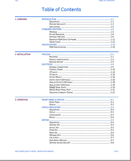
TABLE OF CONTENTS:
Cat Electric Rope Shovel PQM Power Quality Meter GE Multilin Instruction Manual – PDF DOWNLOAD
Overview............................................... 11
	1.1 Introduction................................... 11
		1.1.1 Description.............................. 11
		1.1.2 Feature Highlights....................... 12
		1.1.3 Applications............................. 13
	1.2 Standard Features.............................. 15
		1.2.1 Metering................................. 15
		1.2.2 Future Expansion......................... 16
		1.2.3 Optional Features........................ 16
		1.2.4 EnerVista PQM Setup Software............. 21
		1.2.5 Order Codes.............................. 22
	1.3 Specifications................................. 23
		1.3.1 PQM Specifications....................... 23
Untitled...............................................  1
Installation........................................... 29
	2.1 Physical....................................... 29
		2.1.1 Mounting................................. 29
		2.1.2 Product Identification................... 30
		2.1.3 Revision History......................... 31
	2.2 Electrical..................................... 33
		2.2.1 External Connections..................... 33
		2.2.2 Control Power............................ 43
		2.2.3 VT Inputs................................ 43
		2.2.4 CT Inputs................................ 43
		2.2.5 Output Relays............................ 44
		2.2.6 Switch Inputs (Optional)................. 44
		2.2.7 Analog Outputs (Optional)................ 46
		2.2.8 Analog Input (Optional).................. 47
		2.2.9 RS485 Serial Ports....................... 47
		2.2.10 RS232 Front Panel Port.................. 49
		2.2.11 Dielectric Strength Testing............. 50
Operation.............................................. 51
	3.1 Front Panel & Display.......................... 51
		3.1.1 Front Panel.............................. 51
		3.1.2 Display.................................. 52
	3.2 Status Indicators.............................. 53
		3.2.1 Description.............................. 53
		3.2.2 Status................................... 53
		3.2.3 Communicate.............................. 53
		3.2.4 Relays................................... 54
	3.3 Keypad......................................... 55
		3.3.1 Description.............................. 55
		3.3.2 Setpoint Key............................. 55
		3.3.3 Actual Key............................... 55
		3.3.4 Store Key................................ 55
		3.3.5 Reset Key................................ 56
		3.3.6 Message Keys............................. 56
		3.3.7 Value Keys............................... 57
		3.3.8 Data Entry Methods....................... 57
		3.3.9 Setpoint Access Security................. 58
	3.4 Default Messages............................... 59
		3.4.1 Description.............................. 59
		3.4.2 Adding a Default Message................. 59
		3.4.3 Deleting a Default Message............... 59
Programming............................................ 61
	4.1 Introduction................................... 61
		4.1.1 Setpoint Entry Methods................... 61
	4.2 S1 PQM Setup................................... 63
		4.2.1 Description.............................. 63
		4.2.2 Preferences.............................. 63
		4.2.3 Setpoint Access.......................... 64
		4.2.4 RS485/RS232 Serial Ports................. 67
		4.2.5 DNP 3.0 Configuration.................... 68
		4.2.6 Clock.................................... 69
		4.2.7 Calculation Parameters................... 70
		4.2.8 Clear Data............................... 72
		4.2.9 Event Recorder........................... 74
		4.2.10 Trace Memory............................ 75
		4.2.11 Programmable Message.................... 78
		4.2.12 Product Options......................... 80
	4.3 S2 System Setup................................ 81
		4.3.1 Current/ Voltage Configuration........... 81
		4.3.2 Analog Outputs........................... 84
		4.3.3 Analog Input............................. 89
		4.3.4 Switch Inputs............................ 91
		4.3.5 Pulse Output............................. 93
		4.3.6 Pulse Input.............................. 94
		4.3.7 Data Logger.............................. 96
	4.4 S3 Output Relays............................... 97
		4.4.1 Description.............................. 97
		4.4.2 Alarm Relay.............................. 97
		4.4.3 Auxiliary Relays......................... 98
	4.5 S4 Alarms/Control.............................. 99
		4.5.1 Current/ Voltage Alarms.................. 99
		4.5.2 Total Harmonic Distortion................105
		4.5.3 Frequency................................106
		4.5.4 Power Alarms.............................107
		4.5.5 Power Factor.............................109
		4.5.6 Demand Alarms............................112
		4.5.7 Pulse Input..............................114
		4.5.8 Time.....................................115
		4.5.9 Miscellaneous Alarms.....................117
Monitoring.............................................  0
	5.1 Actual Values Viewing..........................  0
		5.1.1 Description..............................  0
	5.2 A1 Metering....................................119
		5.2.1 Current..................................119
		5.2.2 Voltage..................................121
		5.2.3 Phasors..................................123
		5.2.4 Power....................................125
		5.2.5 Energy...................................130
		5.2.6 Demand...................................132
		5.2.7 Frequency................................133
		5.2.8 Pulse Counter............................134
		5.2.9 Analog Input.............................135
	5.3 A2 Status......................................137
		5.3.1 Alarms...................................137
		5.3.2 Switch Status............................139
		5.3.3 Clock....................................140
		5.3.4 Programmable Message.....................140
	5.4 A3 Power Analysis..............................141
		5.4.1 Power Quality............................141
		5.4.2 Total Harmonic Distortion................142
		5.4.3 Data Logger..............................143
		5.4.4 Event Recorder...........................144
	5.5 A4 Product Info................................149
		5.5.1 Software Versions & Model Information....149
Commissioning..........................................179
	9.1 Commissioning..................................179
Application Notes......................................193
	A.1 Event Recorder.................................193
Index..................................................201
CAT ELECTRIC ROPE SHOVEL PQM POWER QUALITY METER GE MULTILIN INSTRUCTION MANUAL – PDF DOWNLOAD:
IMAGES PREVIEW OF THE MANUAL:
PLEASE NOTE:
- This is the SAME exact manual used by your dealers to fix your vehicle.
- The same can be yours in the next 2-3 mins as you will be directed to the download page immediately after paying for the manual.
- Any queries / doubts regarding your purchase, please feel free to contact [email protected]
S.M