
Cat Electric Rope Shovel Quincy QST Series Air Compressor Instruction Manual – PDF DOWNLOAD
Original price was: $89.00.$24.95Current price is: $24.95.
CAT Electric Rope Shovel 7495 495HF 495HD 141149 – Quincy QST Series Air Compressors – BI619694 – 50310-100-EXT – HD 1 Operation & Maintenance Manuals EN PDF
Description
Cat Electric Rope Shovel Quincy QST Series Air Compressor Instruction Manual – PDF DOWNLOAD
DESCRIPTION:
Cat Electric Rope Shovel Quincy QST Series Air Compressor Instruction Manual – PDF DOWNLOAD
1. GENERAL DESCRIPTION OF QUINCY QST SERIES HELICALSCREW COMPRESSORS
The compressor is a single stage, positive displacement, oil flooded, helical screw type unit. It consists essentially of two rotors that resemble worm gears. The male rotor is driven by a motor through a V belt drive. The male rotor has four lobes that mesh with six grooves in the female rotor. Both rotors are contained in a rotor housing that has two parallel axis and adjoining bores. There is an air inlet port located at the power input end of the cempressm and a discharge port located at the opposite end. Both rotors are mounted in anti-friction bearings at both the suction and discharge ends. The electric motor, compressor and associated equipment is mounted on a top plate.
2. PRINCIPLES OF COMPRESSOR OPERATION
As the rotors rotate, air is drawn into the rotor housing through the air inlet port. This volume of trapped air extends the entire length of the two rotors initially and is prevented from escaping by the unported area of the rotor housing wall. As rotation continues, the lobe on the male rotor enters the groove in the female rotor, thus reducing the volume of trapped air, resulting in continuous compression. Compression continues until the lobe and groove open to the discharge port. At this point, the compressed air is discharged into the line leading to the air/oil reservoir.
3. DESCRIPTION OF AIR FLOW
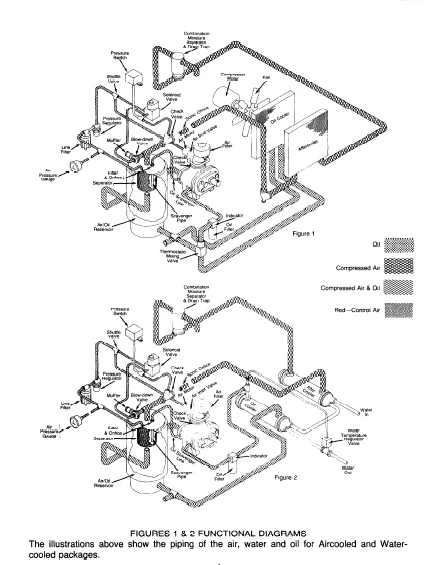
A functional diagram of the air flow system is shown in figure 1. With the compressor operating, a partial vacuum is produced at the compressor inlet. Air entering via the com- pressor air filter, flows through the air inlet valve into the rotor housing where it is com- pressed, then discharged into the air/oil reservoir. The air discharged from the compres- sor contains oil which is removed from the air as the air passes through the air/oil reser- voir and separator element and then through the check valve to the secondary air re- ceiver (if supplied). The quantity of air entering the compressor is regulated by the air inlet valve located between the air intake filter and the compressor inlet port. The position of the air inlet valve is automatically controlled during normal operation by air demand. At start-up, the air inlet valve is full open until the system pressure is established. The air/oil reservoir is equipped with a safety valve to protect the system in the event of a malfunction in the pressure control system.
4. DESCRIPTION OF OIL FLOW AND COMPRESSOR COOLING SYSTEM
- The oil in the system serves three functions; it lubricates the bearings and the rotors, it seals the rotor clearances to improve efficiency, and it removes heat from the air as the air is being compressed thus lowering the compressed air discharge temperature. A functional diagram of the compressor oil flow system is shown in figures 1 & 2. Air pressure in the air/oil reservoir forces oil out of the oil sump, through the oil cooler, through an oil filter equipped with a built in pressure relief valve and then into the com- pressor.
- In the compressor some of the oil is diverted directly to the bearings through internal passages to insure positive lubrication to the bearings and the remainder of the oil is injected into the early stage of the compression cycle to seal clearances and lubricate the rotors. Removal of the heat from the oil is achieved with either an air cooled heat exchanger or a water cooled heat exchanger.
- The air cooled oil cooler is a finned tube unit. A continuous supply of cool air is forced across the fins and tubes by a fan mounted on the compressor motor shaft. Minimum oil injection temperature is controlled by a thermal mixing valve which permits a controlled amount of hot oil to mix with the cooled oil before entering the compressor. The water cooled oil cooler is of the shell and tube construction. Minimum oil injection temperature is controlled by a water regulating valve which senses the oil temperature entering the compressor and regulates the cooling water flowing through the oil cooler. Currently Quincy Compressor does not offer a water cooled system.
5. DESCRIPTION OF THE AIR/OIL RESERVOIR AND AIR/OIL SEPARATOR ELEMENT
- The combination air/oil reservoir consist essentially of a pressure vessel, as shown in figure 3. The air/oil reservoir serves as an oil reservoir and contains the oil separator.
- The discharge line from the compressor enters the reservoir at a point below the normal oil level but turns upward inside the reservoir. The air/oil mixture is discharged into the ‘ reservoir above the oil level and impinges on the underside of the separator.
- The air/oil reservoir is provided with an oil filler opening and sight tube oil level gauge.
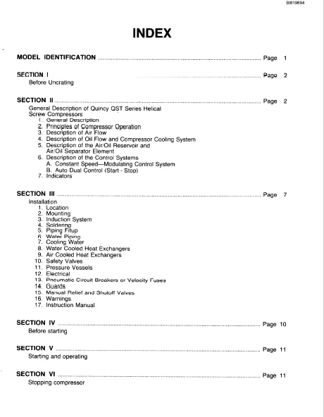
TABLE OF CONTENTS:
Cat Electric Rope Shovel Quincy QST Series Air Compressor Instruction Manual – PDF DOWNLOAD
MODEL IDENTIFICATION
SECTION I
Before Uncrating
SECTION 11 Pag Pa General Description of Quincy QST Series Helical
General Description
Principles of Compressor Operation
Description of Air Flow
Description of Oil Flow and Compressor Cooling System
Description of the Air/Oil Reservoir and
Air/Oil Separator Element
Description of the Control Systems
A Constant Speed—Modulating Control System
B Auto Dual Control (Start – Stop)
Indicators
SECTION Ill page 7
Installation
Location
Mounting
Induction System
Soldering
Piping Fitup
Water Piping
Cooling Water
Water Cooled Heat Exchangers
Air Cooled Heat Exchangers
Safety Valves
Pressure Vessels
Electrical
Pneumatic Circuit Breakers or Velocity Fuses
Guards
Manual Relief and Shutoff Valves
Warnings
Instruction Manual
SECTION IV Page 10
Before starting
SECTION V Page 11
Starting and operating
SECTION VI Page 11
Stopping compressor
BI619694
SECTION Vll Page 12
Preparing for maintenance or service
SECTION Vlll Page 12
Servicing
1 Safety
2 Lubrication
3 Compressor Oil Filter
4 Compressor Air/Oil Separator Element
5 Oil Scavenging System
6 Air Filter
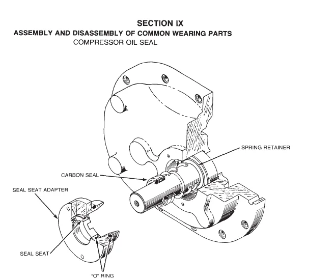
SECTION IX Page 16
Assembly and Disassembly of Common Wearing Parts
1 Compressor Oil Seal (Basic Compressor 124230)
A, Installation
B Analyzing Mechanical Seal Failure
2 Compressor Oil Seal (Basic Compressor 125583)
A Installation
B Analyzing Mechanical Seal Failure
3 Compressor-Vee Belts
A Belt TensIon Adjustment
B Belt Replacement
SECTION X
Trouble Shooting
APPENDIX A
Freight Damage
APPENDIX B
Torque Chart
APPENDIX C
Periodic Safety Check
CAT ELECTRIC ROPE SHOVEL QUINCY QST SERIES AIR COMPRESSOR INSTRUCTION MANUAL – PDF DOWNLOAD:
IMAGES PREVIEW OF THE MANUAL:


PLEASE NOTE:
- This is the same manual used by the dealers to diagnose and troubleshoot your vehicle
- You will be directed to the download page as soon as the purchase is completed. The whole payment and downloading process will take anywhere between 2-5 minutes
- Need any other service / repair / parts manual, please feel free to contact [email protected] . We still have 50,000 manuals unlisted
S.M

Mekhi Cohen –
This is the second order from heydownloads and we couldn’t be happier with the site, pricing, and immediate download!