Cat Feeder Breaker FBL-10 LHD/Utility Service Manual – PDF DOWNLAOD
DESCRIPTION:
Cat Feeder Breaker FBL-10 LHD/Utility Service Manual – PDF DOWNLAOD
General Information
INTRODUCTION
The operation of heavy mining machinery can be hazardous. To ensure safe operation, operators and personnel must be alert, competent, correctly trained, tested and licensed in the principles, capabilities and correct operating and isolation procedures of the machinery.
This manual is designed to provide the FBL-10 LHD/Utility operator and service personnel with the proper information regarding the machine’s instrumentation, operating controls and general safe working procedures. All operators and service personnel of this machine must be conversant with the information contained within this manual before operating or performing service tasks on the machine.
To ensure safe and efficient operation, the FBL-10 LHD/Utility must be adequately maintained by the operators and service personnel. The operator’s pre-start inspection procedure contained in Section 6 of the Operator’s Manual must be performed before the machine is returned to active service.
DESCRIPTION
The FBL-10 is a 10000 kg Load Haul Dump/Utility machine. It allows it to be used for general purpose work throughout the mine, which includes carrying heavy loads, materials and supplies.
The motive force is provided by a 172 kW Caterpillar 3126 turbocharged four-stroke inline six cylinder flameproof diesel engine package. Flameproofing of the system includes a wet exhaust conditioning system complete with exhaust and intake flame traps. The start system is pneumatic.
The diesel control system is an intrinsically safe electronic monitoring system. The engine power output is connected to the constant four-wheel drive system via a drive coupling through a four-speed bidirectional power shift transmission to heavy duty axles. The FBL-10 utilises a wet bath exhaust conditioning system and a catalysed exhaust post treatment purifier.
A removable flame trap for ease of cleaning is fitted on the outlet of the exhaust conditioner housing.
TABLE OF CONTENTS:
Cat Feeder Breaker FBL-10 LHD/Utility Service Manual – PDF DOWNLAOD
M01379.pdf.........................................................................................................................................................................................................................................................................................  0
	Service Manual - Cover Page....................................................................................................................................................................................................................................................................  2
	Table of Contents..............................................................................................................................................................................................................................................................................  3
	Section 1 General Information..................................................................................................................................................................................................................................................................  9
		Introduction
..............................................................................................................................................................................................................................................................................  9
		Description
...............................................................................................................................................................................................................................................................................  9
		SAFETY LABELS AND INSTRUCTIONS
............................................................................................................................................................................................................................................................ 10
		Gauge colour code
......................................................................................................................................................................................................................................................................... 11
		Gauge alarm parameters
.................................................................................................................................................................................................................................................................... 11
		GENERAL ARRANGEMENT
....................................................................................................................................................................................................................................................................... 13
		specifications
............................................................................................................................................................................................................................................................................ 14
		All specifications are subject to change without notice. Always consult BUCYRUS to obtain current information before applying critical loads.
............................................................................................................................................. 14
		Capacities
................................................................................................................................................................................................................................................................................ 14
		Weight
.................................................................................................................................................................................................................................................................................... 14
		Pneumatic System
.......................................................................................................................................................................................................................................................................... 15
		Lubrication and Fuel Specifications
....................................................................................................................................................................................................................................................... 16
		General
................................................................................................................................................................................................................................................................................... 16
		Fuels
..................................................................................................................................................................................................................................................................................... 16
		Fuel Specification Table
.................................................................................................................................................................................................................................................................. 16
		Fuel Additives
............................................................................................................................................................................................................................................................................ 17
		Diesel Fuel Relevant Information
.......................................................................................................................................................................................................................................................... 18
		Fuel handling
............................................................................................................................................................................................................................................................................. 18
		Low Temperature Effects
................................................................................................................................................................................................................................................................... 18
		Exhaust Emissions
......................................................................................................................................................................................................................................................................... 18
		Engine Maintenance
........................................................................................................................................................................................................................................................................ 18
		Engine Oil
................................................................................................................................................................................................................................................................................ 19
		Torque Converter/Transmission Fluid
....................................................................................................................................................................................................................................................... 19
		Hydraulic Oil
............................................................................................................................................................................................................................................................................. 19
		Gear Oil
.................................................................................................................................................................................................................................................................................. 19
		Multi-Purpose EP Grease
................................................................................................................................................................................................................................................................... 19
		Drive Coupling Grease
..................................................................................................................................................................................................................................................................... 20
		Exhaust Conditioner Make Up Tanks
......................................................................................................................................................................................................................................................... 20
		Fluid specification table
................................................................................................................................................................................................................................................................. 21
		Machine Isolation
......................................................................................................................................................................................................................................................................... 23
		Engine Isolation
.......................................................................................................................................................................................................................................................................... 23
		Pneumatic Isolation
....................................................................................................................................................................................................................................................................... 24
		Hydraulic isolation
....................................................................................................................................................................................................................................................................... 25
		Engine Coolant Isolation
.................................................................................................................................................................................................................................................................. 26
		Electrical Isolation
...................................................................................................................................................................................................................................................................... 26
		Articulation Isolation
.................................................................................................................................................................................................................................................................... 27
		Lift Arm Isolation
........................................................................................................................................................................................................................................................................ 28
		Exhaust Conditioner Isolation
............................................................................................................................................................................................................................................................. 29
		General Safety and Precautions
............................................................................................................................................................................................................................................................ 30
		General
................................................................................................................................................................................................................................................................................... 30
		Packing/Supporting the Machine
............................................................................................................................................................................................................................................................ 33
		MAINTENANCE SCHEDULES
..................................................................................................................................................................................................................................................................... 34
		Maintenance Inspections
................................................................................................................................................................................................................................................................... 34
		FBL-10 LHD/Utility Vehicle – Lubrication Reference
........................................................................................................................................................................................................................................ 43
		FBL-10 LHD/Utility Vehicle – Lubrication Reference
........................................................................................................................................................................................................................................ 54
		FBL-10 LHD/Utility Vehicle – Lubrication Reference
........................................................................................................................................................................................................................................ 65
		FBL-10 LHD/Utility Vehicle – Lubrication Reference
........................................................................................................................................................................................................................................ 77
		FBL-10 LHD/Utility Vehicle – Lubrication Reference
........................................................................................................................................................................................................................................ 89
		FBL-10 LHD/Utility Vehicle – Lubrication Reference
........................................................................................................................................................................................................................................101
		FBL-10 LHD/Utility Vehicle – Lubrication Reference
........................................................................................................................................................................................................................................113
		FBL-10 LHD/Utility Vehicle – Lubrication Reference
........................................................................................................................................................................................................................................126
		Recommended Bolt Torque
...................................................................................................................................................................................................................................................................127
	Section 2 Engine System........................................................................................................................................................................................................................................................................129
	Section 3 Transmission and Drive Train.........................................................................................................................................................................................................................................................175
	Section 4 Hydraulic System_Danfoss.............................................................................................................................................................................................................................................................203
		General description
.......................................................................................................................................................................................................................................................................203
		Safety precautions
........................................................................................................................................................................................................................................................................204
		Hydraulic Isolation
.......................................................................................................................................................................................................................................................................205
		Pumps and mountings
.......................................................................................................................................................................................................................................................................206
		Steering/Brake Pump
.......................................................................................................................................................................................................................................................................206
		Main Hydraulic Pump
.......................................................................................................................................................................................................................................................................209
		Auxiliary hydraulic pumps
.................................................................................................................................................................................................................................................................210
		Hydraulic tank
............................................................................................................................................................................................................................................................................211
		Checking and filling hydraulic oil
........................................................................................................................................................................................................................................................211
		Changing hydraulic oil
....................................................................................................................................................................................................................................................................212
		Checking and cleaning filler neck screen
..................................................................................................................................................................................................................................................213
		Checking and replacing the return filter
..................................................................................................................................................................................................................................................214
		Steering/brake pump pressure filter
.......................................................................................................................................................................................................................................................219
		Steering circuit
..........................................................................................................................................................................................................................................................................221
		Steering accumulator
......................................................................................................................................................................................................................................................................221
		Steering control valve
....................................................................................................................................................................................................................................................................222
		Brake circuit
.............................................................................................................................................................................................................................................................................223
		Brake accumulator
.........................................................................................................................................................................................................................................................................223
		Brake Valve
...............................................................................................................................................................................................................................................................................224
		Brake Heads
...............................................................................................................................................................................................................................................................................228
		CONTROL LEVERS
............................................................................................................................................................................................................................................................................229
		Main Control Valve Bank
...................................................................................................................................................................................................................................................................231
		Tilt and Lift Circuits
....................................................................................................................................................................................................................................................................233
		RAS Attach and PTO Circuits
...............................................................................................................................................................................................................................................................234
		Alternator Circuit and Cooling Fan
........................................................................................................................................................................................................................................................235
	Section 4 Hydraulic Schematic..................................................................................................................................................................................................................................................................237
		Hydraulic schematic
.......................................................................................................................................................................................................................................................................237
	Section 5 Electrics, Instruments and Controls..................................................................................................................................................................................................................................................239
		Electrical system
.........................................................................................................................................................................................................................................................................239
		General description
.......................................................................................................................................................................................................................................................................239
		Safety Precautions
........................................................................................................................................................................................................................................................................239
		Electric lighting components
..............................................................................................................................................................................................................................................................241
		ENGINE SERVICE HOUR meter
.................................................................................................................................................................................................................................................................244
		Electrical system troubleshooting
.........................................................................................................................................................................................................................................................246
		ALTERNATOR AND DRIVE ASSEMBLY
.............................................................................................................................................................................................................................................................247
		GENERAL DESCRIPTION
.......................................................................................................................................................................................................................................................................247
		Safety precautions
........................................................................................................................................................................................................................................................................247
		ALTERNATOR ASSEMBLY
.......................................................................................................................................................................................................................................................................247
		Alternator Drive Assembly
.................................................................................................................................................................................................................................................................249
		Electronic Shutdown System
................................................................................................................................................................................................................................................................250
		General Description
.......................................................................................................................................................................................................................................................................250
		Power supply
..............................................................................................................................................................................................................................................................................250
		Display assemblies
........................................................................................................................................................................................................................................................................252
		General Arrangements
......................................................................................................................................................................................................................................................................254
		switches
..................................................................................................................................................................................................................................................................................255
		SENSORS
...................................................................................................................................................................................................................................................................................255
		Sensor locations
..........................................................................................................................................................................................................................................................................255
		INSTRUCTIONS FOR electronic shutdown system METHANE SENSOR HEAD
...........................................................................................................................................................................................................................260
		Checks and Calibration of the TX6383 CH4 TROLEX
...........................................................................................................................................................................................................................................261
		Unit should be in fresh air, or fresh air is to be supplied. The unit should have the GREEN LED illuminated.
..............................................................................................................................................................................261
		Check reading. If not zero go to Step 3. If the unit reads zero there is no need to zero. (Go to Step 6).
.................................................................................................................................................................................261
		To calibrate zero hold both buttons in for three seconds LED will go to RED which means the unit is in Calibration Mode.
..................................................................................................................................................................261
		Whilst the RED LED is illuminated press and hold the bottom button until the LED is flashing GREEN.
.......................................................................................................................................................................................261
		Release button and the unit will auto zero, after auto zeroing the unit will go to normal operating mode. The LED will go to GREEN.
.......................................................................................................................................................261
		Turn the zero gas off.
....................................................................................................................................................................................................................................................................261
		Apply the nominal span gas. Allow for sufficient time for reading to be stable. The reading should be ±10% of reading or ±5% of full scale whichever is least.
............................................................................................................................261
		If reading is outside of tolerance got to the Step 9. If the reading is within the tolerance turn gas off and allow reading to go back to zero. (Go to Step 12)
..........................................................................................................................261
		Press and hold both buttons for three seconds. Span gas must be left on at this stage. The LED will go to RED
............................................................................................................................................................................261
		Press and hold the top button until the LED is flashing ORANGE. With the buttons adjust the reading on the display to match that of the nominal gas applied. You have five seconds to press a button. If you do not press a button in this time the unit will go to normal operations.
....261
		Take gas off the sensor and allow it to go back to zero. Reapply gas to verify the calibration.
...........................................................................................................................................................................................261
		Let sensor zero in air and turn off gas cylinders. The LED should be back to GREEN.
.......................................................................................................................................................................................................261
		System Operation
..........................................................................................................................................................................................................................................................................263
		Testing methane sensor
....................................................................................................................................................................................................................................................................264
		Fault diagnosis guide
.....................................................................................................................................................................................................................................................................265
		INSTRUMENTS AND CONTROLS
..................................................................................................................................................................................................................................................................267
		Compartment door
..........................................................................................................................................................................................................................................................................267
		Transmission gear control lever
...........................................................................................................................................................................................................................................................268
		Transmission Directional Control Lever
....................................................................................................................................................................................................................................................268
		Park Brake button
.........................................................................................................................................................................................................................................................................269
		FOUR-WAYJOYSTICK control lever
............................................................................................................................................................................................................................................................270
		No. 2 - TWO-WAY HYDRAULIC Control Lever
...................................................................................................................................................................................................................................................270
		No. 1 - TWO-WAY HYDRAULIC control lever
...................................................................................................................................................................................................................................................270
		CONTROL LEVER MAINTENANCE
.................................................................................................................................................................................................................................................................271
		Operator’s Seat
...........................................................................................................................................................................................................................................................................272
		Accelerator Pedal
.........................................................................................................................................................................................................................................................................272
		Brake pedal
...............................................................................................................................................................................................................................................................................272
		STEERING WHEEL
............................................................................................................................................................................................................................................................................273
		Brake head pressure gauge
.................................................................................................................................................................................................................................................................274
		Brake accumulator pressure gauge
..........................................................................................................................................................................................................................................................274
		Steering accumulator pressure gauge
.......................................................................................................................................................................................................................................................274
		Engine Start Button
.......................................................................................................................................................................................................................................................................275
		On/Off Toggle Switch
......................................................................................................................................................................................................................................................................275
		Air pressure gauge
........................................................................................................................................................................................................................................................................275
		Transmission Oil Temperature Gauge
........................................................................................................................................................................................................................................................276
		Engine Coolant Temperature Gauge
..........................................................................................................................................................................................................................................................276
		Horn button
...............................................................................................................................................................................................................................................................................277
		Emergency Fuel Shut Off Valve
.............................................................................................................................................................................................................................................................277
		Air Cleaner Service Indicator
.............................................................................................................................................................................................................................................................278
		Engine SERVICE Hour Meter
.................................................................................................................................................................................................................................................................278
		Engine Oil Pressure Gauge
.................................................................................................................................................................................................................................................................279
		Shutdown System Test Valve
................................................................................................................................................................................................................................................................279
		ENGINE fuel Primer Pump
...................................................................................................................................................................................................................................................................280
		RAS Pilot lock cylinder release button
....................................................................................................................................................................................................................................................280
		Attachment quick connects button
..........................................................................................................................................................................................................................................................280
		Emergency Intake Shut Off Valve
...........................................................................................................................................................................................................................................................281
	Section 6 Frame Components.....................................................................................................................................................................................................................................................................283
	Section 7 Pneumatic System.....................................................................................................................................................................................................................................................................301
	Section 8 Attachments..........................................................................................................................................................................................................................................................................315
CAT FEEDER BREAKER FBL-10 LHD/UTILITY SERVICE MANUAL – PDF DOWNLAOD:
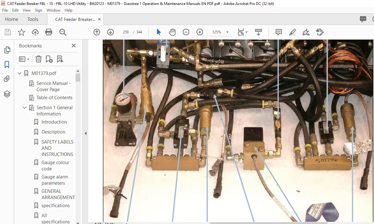
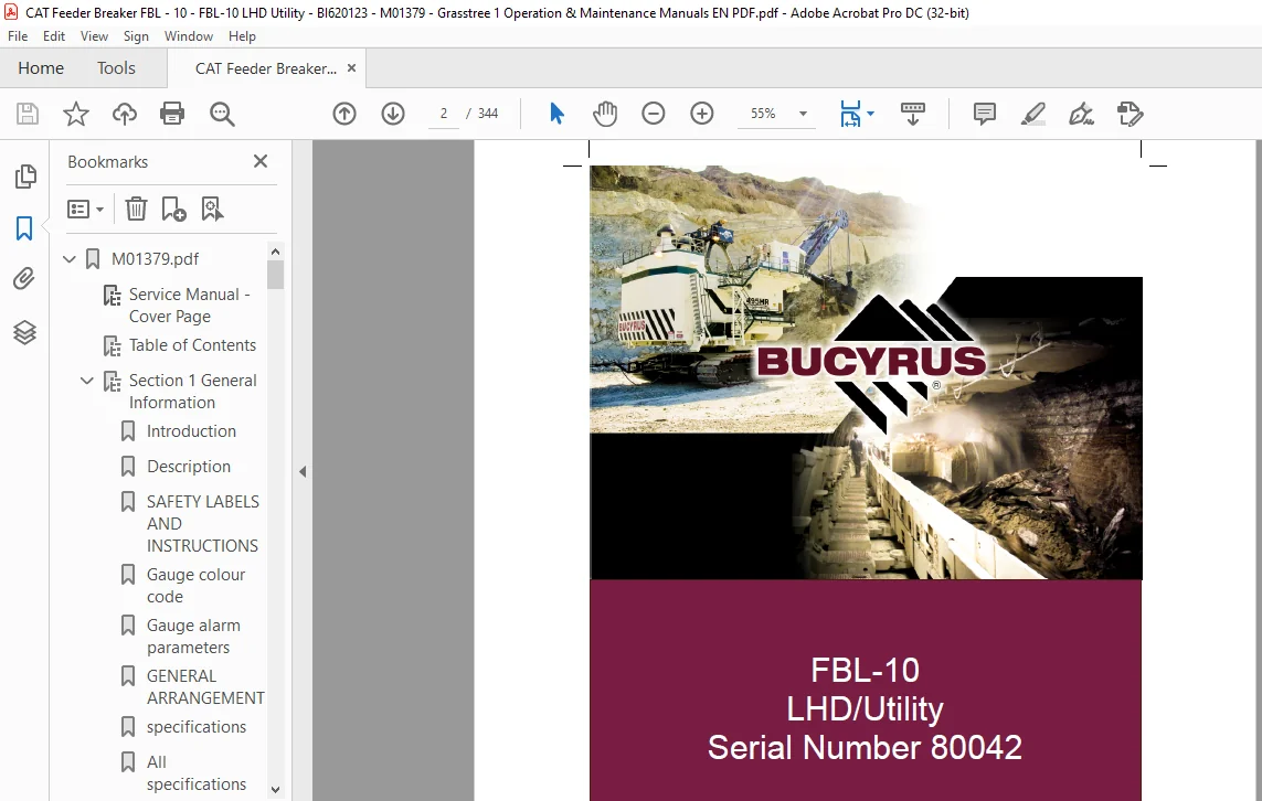
IMAGES PREVIEW OF THE MANUAL:
Cat Feeder Breaker FBL-10 LHD/Utility Service Manual – PDF DOWNLAODCat Feeder Breaker FBL-10 LHD/Utility Service Manual – PDF DOWNLAOD
PLEASE NOTE:
This is the same manual used by the DEALERSHIPS to SERVICE your vehicle.
The manual can be all yours – Once payment is complete, you will be taken to the download page from where you can download the manual. All in 2-5 minutes time!!
Need any other service / repair / parts manual, please feel free to contact us at heydownloadss @gmail.com . We may surprise you with a nice offer
S.M
✹
What Our Customers Say
★★★★★Live reviews from customers
Loading customer reviews...
🌟 Related Products
Discover more professional manuals for your equipment