
Cat Lift Trucks S6S Diesel Engine Parts Manual 98735-50000 – PDF Download
Original price was: $59.95.$39.95Current price is: $39.95.
Complete illustrated Cat Lift Trucks S6S diesel engine parts manual, publication 98735-50000. Covers E35AFL, E35BFL, E35CFL, Y35AFL and Z35AFL with exploded views, genuine part numbers, quantities and model applicability for every engine assembly.
Description
Cat Lift Trucks S6S Diesel Engine Parts Manual – Publication 98735-50000
This is the full illustrated Cat Lift Trucks S6S Diesel Engine Parts Manual, issued under document number 98735-50000. It is the parts catalogue for the S6S diesel engine as installed in Cat lift truck models E35AFL, E35BFL, E35CFL, Y35AFL and Z35AFL across the SGS 25Amp, 50Amp and 75Amp build variations. Every engine assembly is broken down to component level and presented with reference numbers that tie directly to the accompanying exploded illustrations, so a part can be identified visually and then confirmed against its part number, quantity and model column before it is ordered or fitted.
Because this is the parts manual and not a service guide, its strength is identification: it tells you what each component is, how it sits in relation to the parts around it, how many are required per engine, and which of the five listed truck models uses it. That makes it the reference to keep open on the bench whenever an S6S engine is being stripped, rebuilt, resealed or simply re-ordered after a failure.
File Details
- Manual type: Illustrated Parts Manual
- Brand: Cat Lift Trucks
- Engine: S6S diesel
- Models covered: E35AFL, E35BFL, E35CFL, Y35AFL, Z35AFL (SGS 25Amp, 50Amp and 75Amp)
- Publication number: 98735-50000
- Language: English
- Page count: 132
- File format: PDF
Chapters Covered
- Engine Body
- Inlet & Exhaust System
- Lubrication System
- Cooling System
- Fuel System
- Starting System
- Instrument
- Repair Parts
Engine Body
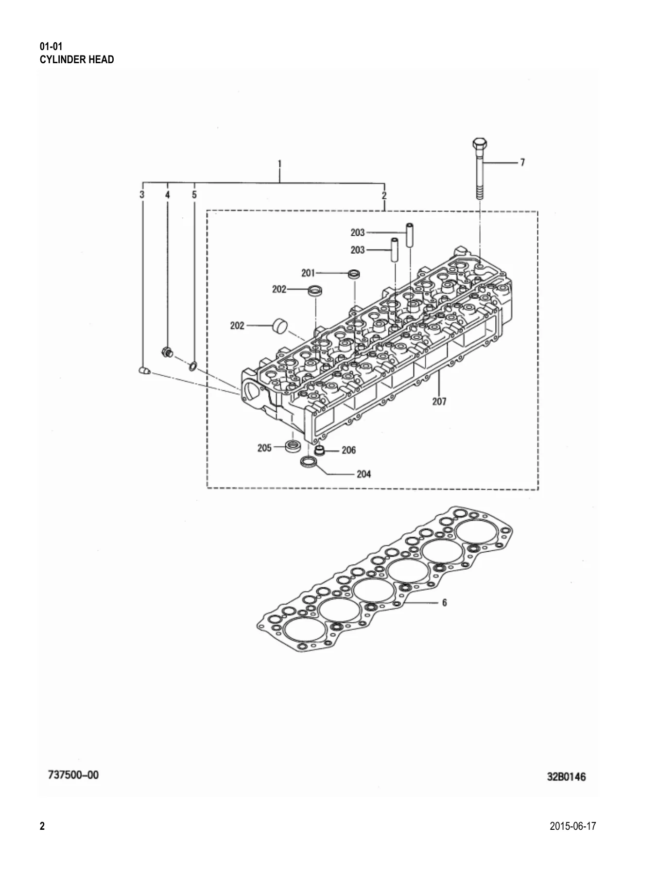
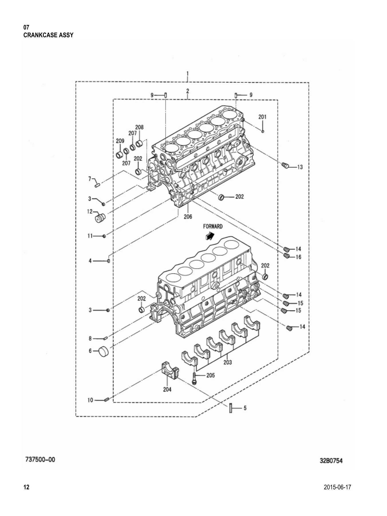
The core of the manual and by far the largest group. It opens with the Cylinder Head assembly and its sealing caps, valve guides and valve seats, then moves through the Lifting Eye, the complete Valve Mechanism (inlet and exhaust valves, outer springs, retainers, cotters, stem seals and the rocker and shaft assembly) and the Rocker Cover with its breather pipe and oil filler cap. From there the Camshaft & Tappet group details the camshaft, Woodruff key, thrust plate, tappets and pushrods. The Crankcase Assembly section lists the crankcase sub-assembly, bearing caps, camshaft bushings, dowel and spring pins, taper plugs and the idler shaft, followed by the Rear Plate and its oil seal, and the Main Metal group with standard and undersize main bearing sets, thrust plates and their 0.15 and 0.30 oversizes. The Timing Gear Case covers the front plate, gear case, gaskets, timing gear cover, oil seal assembly and pointer plate. Reciprocating parts follow: Piston in standard and 0.25 / 0.50 oversizes with piston ring sets, piston pins and snap rings; Connecting Rod assemblies with rod bolts, bushings and connecting rod metal sets in standard and three oversizes; and the Crankshaft group with its dowel pin, Woodruff key, crankshaft nut and crankshaft gear, plus the separate Crank Pulley. The group closes with the Flywheel assembly and ring gear, the Torsional Damper, and the Timing Gear set covering the camshaft gear, injection pump gear, idler assembly with bushing and gear, thrust plate and the oil pump gear.
Inlet & Exhaust System
Covers the Inlet System with the inlet manifold assembly and breather pipe, and the separate Inlet Pipe with its air inlet elbow, air heater gasket and mounting hardware. The Exhaust System section lists the exhaust manifold, its gasket, studs, spacers, washers and bolts.
Lubrication System
The Oil Pump group gives the oil pump assembly with its O-ring and mounting hardware, and the Oil Strainer section covers the strainer, O-ring and stay. The Oil System adds the safety valve assembly and gasket. The Oil Cooler group details the crankcase side cover and side cover gasket, and the Oil Filter section lists the cartridge assembly and oil filter union. The Breather group covers the breather hose and both clamps, routed to the inlet manifold.
Cooling System
The Water Pump group includes both water pump gasket part numbers, the pump assembly, water pump cover, water pipe, taper plug, pump cover gasket and the mounting bolt sizes. The Water Pump Pulley is listed separately. The Cooling System section covers the hose clamp, thermostat assembly, thermostat cover, thermostat gasket, elbow gasket, thermostat case assembly and the by-pass hose. The Fan and Fan Spacer groups give the cooling fan, plate, spacer and bolts, and the V-Belt section lists the low edge V-belt.
Fuel System
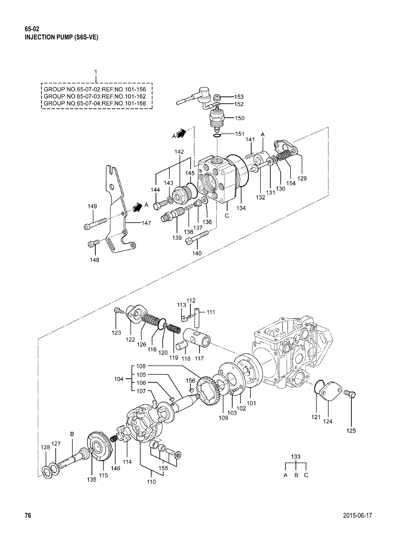
A detailed group that starts with the Nozzle assembly – nozzle holder, nozzle body, pressure pin and spring, retaining nut and distance piece – plus the full range of adjusting washers from T=0.900 through T=1.950 for setting nozzle opening pressure, and the nozzle tip assembly. The Fuel System section lists fuel return and leak-off pipes, hoses, clamps, stays and clips, and the six numbered injection pipes. The Fuel Filter group covers the filter assembly, body, element kit, fuel filter sensor and plugs. The Injection Pump (S6S-VE) is split across four sub-sections and is the most granular part of the manual: pump assembly, feed pump, drive shaft assembly and key, damper, gear, roller assembly, pins and clips, cam disk, O-rings, piston, slider, timer springs and the extensive shim selection (both timer shims and the distributor shim range from T=1.90 to T=2.32), the guide pin, heat distributor, magnet valve, wire, plunger spring kit and roller kit. The governor section adds the governor cover assembly, control shaft, governor levers and their mark numbers, load screws in three lengths, governor shaft, governor spring, pivot bolt and the closing plug range from L=2.10 up to L=5.90.
Starting System
The Starter (12V-3KW) group breaks the starter down fully – screw sets, switch assembly, bracket, plain bearing, shift lever, ball, packing set, armature assembly, pinion set, stopper kit, over-running clutch, internal gear, gear shaft, brush springs and brush holder. The Glow Plug & Wire section covers the glow plugs and connection plate. Five Alternator sections follow: the alternator general assemblies for the E35AFL, E35BFL, Y35AFL and Z35AFL, the alternator general for the E35CFL, and the 12V-50A, 12V-75A and 12V-25A alternator builds – each with pulley, rotor, stator, front and rear brackets, regulator set, brush set, rectifier and bearing part numbers.
Instrument & Repair Parts
The Instrument section lists the oil pressure switch. The Repair Parts chapter is the overhaul gasket kit, broken out line by line so every gasket, O-ring and seal included in the kit is shown with its own part number and quantity.
Maintenance Parts, Interchangeability and Indexes
Near the front of the manual is a Maintenance Parts table that groups the service items – oil pressure switch, starter assembly, connection plate, fuel element kit and fuel filter sensor, injector pump filter, glow plug filter, V-belt, oil filler cap and oil filter cartridge – with the service interval notes printed against them. The general information chapter explains the interchangeability codes used throughout the lists (R, 1, 3, N and G) so you know whether a new part number is a direct substitute for an old one, whether it must be fitted in combination with another part, or whether the two are simply not interchangeable. An Alpha Index and a Numeric Index at the back let you jump straight from a part number or part name to its reference number and page.
Why This Parts Manual Belongs in the Workshop
Ordering the wrong part for an S6S diesel is an expensive way to lose a day. This manual removes that risk. The exploded illustrations show how the engine goes together, and the lists beside them give the part number, the description, the quantity required per engine and the model applicability, so a main bearing set, a shim of the correct thickness, a nozzle adjusting washer or a specific alternator brush set can be confirmed on paper before anyone reaches for a phone.
It is equally useful during a rebuild. Working from the illustrations you can see the order in which components stack – the rocker shaft assembly, the camshaft thrust plate, the idler gear and thrust plate, the injection pump cam disk and slider, the thermostat case and by-pass hose – and because quantities are listed, nothing gets overlooked on the re-order. The oversize and undersize options are spelled out too: main metal sets, connecting rod metals and pistons in standard and oversizes, thrust plates, and the full shim and closing plug ranges, all with their own numbers so the correct size is selected the first time.
IMAGES PREVIEW
Delivery is instant. The file is a PDF that downloads immediately after payment, with no shipping and no waiting for a printed book. Open it on a laptop in the workshop, a tablet on the machine or a phone at the parts counter, zoom into the exploded views as far as the screen allows, and print the pages you need for the job in front of you. It is a Cat Lift Trucks S6S diesel engine parts manual built to be used, not shelved – keep it with the truck and it will pay for itself the first time it stops you ordering the wrong component.
Reviews
There are no reviews yet.