Cat MD5125 Hydraulic Track Drill Service Manual – PDF DOWNLOAD
Original price was: $89.95.$39.95Current price is: $39.95.
Cat MD5125 Hydraulic Track Drill Service Manual – PDF DOWNLOAD
Description
Cat MD5125 Hydraulic Track Drill Service Manual – PDF DOWNLOAD
IMAGES PREVIEW OF THE MANUAL:


DESCRIPTION:
Cat MD5125 Hydraulic Track Drill Service Manual – PDF DOWNLOAD
PARTS ORDERING AND PRODUCT SUPPORT
Use only genuine Cat® parts in the maintenance, rebuild or repair of these machines. The manufacturer shall have no liability as to any unauthorized modification of machines or parts. The manufacturer is also not obligated or liable for any machines or parts that have been improperly handled; that have not been operated, maintained or repaired according to furnished manuals or other written instructions, and that have been operated with other than genuine Cat parts or authorized OEM components.
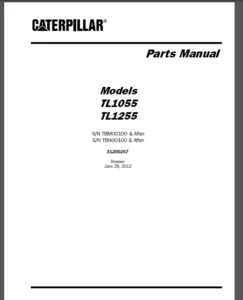
IDENTIFICATION OF THE MACHINE
Always furnish the Model Number and Serial Number when ordering parts. This information is found on the machine nameplate.
PART NUMBER AND DESCRIPTION
In addition to the Model and Serial Number, always give the part number and description of each part ordered. If there is any doubt as to the correct part number and description, furnish a dimensional sketch or return the part to be replaced, transportation charges prepaid. Your cooperation in furnishing as much information as possible will assist us in filling your orders correctly and in the shortest possible time.
SHIPMENT
Unless otherwise instructed, all shipments will be made via motor freight collect, freight forwarder or UPS prepaid and charged on our invoice. Shipments cannot be made on open account until your credit has been approved by our accounting department.
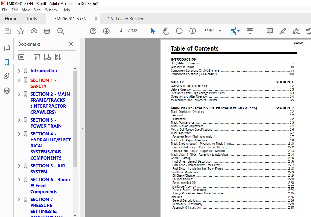
TABLE OF CONTENTS:
Cat MD5125 Hydraulic Track Drill Service Manual – PDF DOWNLOAD
INTRODUCTION
U S /Metric Conversions x
Glossary of Terms xii
Component Locations (C-10/11 engine) xiv
Component Locations (3306 engine) xviii
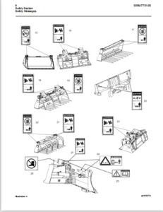
SAFETY SECTION 1
Overview of Potential Hazards 1-2
Before Operation 1-3
Clearances from High Voltage Power Lines 1-3
Operation and After Operation 1-4
Maintenance and Equipment Transfer 1-5
MAIN FRAME/TRACKS (INTERTRACTOR CRAWLERS) SECTION 2
Track Oscillation Cylinders 2-2
Removal 2-2
Installation 2-2
Track Maintenance 2-3
Track Tension Adjustment 2-4
Metric Bolt Torque Specifications 2-6
Track Assembly 2-7
Separate Track Chain Assembly 2-7
Track Link – Repair & Replace 2-8
Track Shoe (grouser) – Mounting to Track Chain 2-10
Grouser Bolt Torque (Direct Torque Method) 2-12
Grouser Bolt Torque (Torque Turn Method) 2-13
Track Chain & Shoe – Assembly & Installation 2-14
Crawler Carriage 2-16
Final Drive – General Description 2-16
Final Drive – Removal from Track Frame 2-17
Final Drive – Installation into Track Frame 2-18
Final Drive Maintenance 2-19
Oil Check/Change 2-19
Oil Specifications 2-20
Recommended Oils 2-20
Final Drive Assembly 2-22
Parking Brake – Description 2-24
Towing Procedure – Gear Drive Disconnect 2-25
Idler Unit 2-26
General Description 2-26
Removal & Disassembly 2-28
Assembly & Installation 2-30
BI006829
Introduction iii
Table of Contents
MAIN FRAME/TRACKS (INTERTRACTOR CRAWLERS) SECTION 2
Track Rollers – General Description 2-33
Removal & Disassembly 2-34
Assembly 2-36
Test & Installation 2-37
Support Rollers – General Description 2-38
Removal & Disassembly 2-39
POWER TRAIN SECTION 3
Hydraulic Pumps 3-2
Hydraulic Pumps – Removal and Installation 3-2
Hydraulic Pump – Repair 3-2
Pump Drive 3-3
Funk Pump Drive – Removal 3-3
Funk Pump Drive – Repair, Inspection, Assembly, Installation & Lubrication 3-7
Terrell Pump Drive – Repair, Inspection & Assembly 3-9
Terrell Pump Drive – Bearing Setting Procedure 3-10
Terrell Pump Drive – Installation & Lubrication 3-12
Hydraulic Pump Retrofit Procedure 3-13
Rexroth Pump Installation 3-14
Parts List 3-15
Procedure for Replacing a PVD45 Vickers Pump with a A11VLO Rexroth Pump 3-16
Fuel System – Cat 3306 Engine 3-22
Fuel Tank Maintenance 3-22
Fuel Filters – Every 250 Hours of Operation 3-23
Priming the Fuel System 3-23
Fuel System – Cat C-10 & 11 Engine 3-24
Fuel Tank Maintenance 3-24
Fuel Filters – Every 250 Hours of Operation 3-25
Priming the Fuel System 3-25
Coolers – Cat 3306 Engine 3-26
Engine Radiator – Capacity and Service 3-26
Coolant Specifications 3-27
Coolers – Cat C-10 & 11 Engine 3-28
Engine Radiator – Capacity and Service 3-28
Coolant Specifications 3-29
Compressor Oil Cooler (Cat 3306) – Removal & Installation 3-30
Radiator/Oil Cooler (Cat 3306) – Removal & Installation 3-31
Radiator/Oil Cooler (Cat C-10 & 11) – Removal & Installation 3-32
BI006829
iv Introduction
Table of Contents
HYDRAULIC/ELECTRICAL SYSTEMS/CAB COMPONENTS SECTION 4
Welding Caution 4-1
Hydraulic System 4-2
Basic Hydraulic Schematic (Vickers Pumps) 4-3
Basic Hydraulic Schematic (Rexroth Pumps) 4-4
Basic Hydraulic Schematic (Linde Pumps) 4-5
Tram Console with Boom Hosing 4-6
Hydraulic Schematic – Drill Console 4-7
Hydraulic Schematic – Cab 4-9
Rod Changer Piping 4-11
Boom Piping 4-12
Hydraulic Valves – Maintenance 4-13
Boom/Feed Pilot Valve 4-13
Pilot Tube Cleaning Instructions 4-13
Tram Pilot Valve 4-14
Pilot Tube Cleaning Instructions 4-14
Electrical Arrangement – 3306 Engine 4-15
D C Schematic – Non-Cab Machine (3306 Engine) 4-18
D C Schematic – with Cab (3306 Engine) 4-20
Wiring Diagram – with Cab (3306 Engine) 4-26
Wire Number/Color Code Chart – Cab to Main Junction Box (3306 Engine) 4-29
Wire Number/Color Code Chart – Inside Cab (3306 Engine) 4-30
Wiring Diagram – Boom Control Panel 4-32
Wiring Diagram – Drill Control Panel 4-33
Wiring Diagram – Tram Control Panel 4-34
Wiring Diagram – Instrument Panel (3306 Engine) 4-35
Air Ride Seat Assembly 4-36
Air Ride Seat – Removal/Installation and Repair 4-38
Electrical Arrangement – C-10 Engine 4-41
D C Schematic – with Cab (C-10 & 11 Engine) 4-44
Wiring Diagram – Instrument Panel (C-10 & 11 Engine) 4-49
Wiring Diagram – with Cab (C-10 & 11 Engine) 4-50
Electrical Arrangement – C-11 Engine 4-52
AIR SYSTEM SECTION 5
Air Receiver Tank 5-2
Preventive Maintenance 5-2
Compressor Oil Separator Element: 5-2
Preventive Maintenance 5-2
Air Receiver Tank – Troubleshooting 5-4
Air System Components 5-6
Compressor Oil Piping 5-7
Thermostatic Bypass Valve 5-7
Air Valve Piping (cab machines) 5-8
Air Valve Piping (non-cab machines) 5-9
Compressor Assembly – 350 CFM 5-10
BI006829
Introduction v
Table of Contents
Compressor Unit – 350 CFM 5-11
Removal and Installation 5-11
Drive Coupling – Replacement 5-11
Air Compressor Drive Motor (fixed displacement) 5-12
Air Compressor Drive Motor (variable displacement) 5-13
Adjustment and Case Drain Pressure 5-13
Detergent Tank Piping 5-14
BOOM & FEED COMPONENTS SECTION 6
Boom Lift Cylinder – Removal 6-2
Boom Lift Cylinder – Replace 6-3
Cylinder Bleeding Procedure and Final Installation: 6-3
Boom Swing Cylinder – Removal 6-4
Boom Swing Cylinder – Replace 6-5
Cylinder Bleeding Procedure and Final Installation: 6-5
Feed Dump Cylinder – Removal 6-6
Feed Dump Cylinder – Replace 6-7
Cylinder Bleeding Procedure and Final Installation: 6-7
Feed Swing Cylinder – Removal 6-9
Feed Swing Cylinder – Replace 6-11
Cylinder Bleeding Procedure and Final Installation: 6-11
Feed Swing Cylinder – Indexing 6-12
Feed Extension Cylinder – Removal 6-15
Feed Extension Cylinder – Replace 6-17
Cylinder Bleeding Procedure and Final Installation: 6-17
Boom Shim/Wear Pad Replacement 6-18
Boom Wear Pads – Inspection 6-19
Feed and Feed Table (early style) – Removal from Boom 6-20
Feed and Feed Table (late style) – Removal from Boom 6-22
Inner Boom Tube – Removal 6-25
Rear Wear Pads and Shims – Installation 6-27
Front Wear Pads and Shims – Installation 6-29
Feed and Feed Table – Installation on Boom 6-30
Boom Wear Pads – Final Inspection 6-33
HPR2 Hydraulic Rock Drill 6-34
Removal from Feed 6-35
Installation on Feed 6-35
Mounting Slide Adjustment 6-36
Feed Chain Tension 6-37
Adjustment 6-37
Traveling Hose Reel Timing 6-39
Feed Table Wear Pad Adjustment 6-40
Feed Table Pivot Pin Adjustment & Maintenance 6-41
AIR SYSTEM SECTION 5
BI006829
vi Introduction
Table of Contents
PRESSURE SETTINGS & ADJUSTMENTS SECTION 7
Engine Adjustments – Cat 3306 7-2
Engine Low Idle 7-2
Engine High Idle 7-2
Engine Adjustments – Cat C-10 & 11 7-4
ECM Diagnostic Light 7-5
Brake Valve Adjustments 7-6
Brake Valve Adjustment (with Vickers Main Pumps) 7-7
Brake Sequence Valve – Bench Test Procedure 7-8
Brake Valve Adjustment (with Rexroth/Linde Main Pumps) 7-9
Tram System 7-10
Counterbalance Valve – Adjustment Procedure 7-11
Tram Circuit Diagram 7-12
Tram Counterbalance Valve – Bench Test Procedure 7-13
Tram Valve /Joystick Adjustments 7-14
Joystick Adjustment: 7-14
Adjustment Procedures & Troubleshooting 7-17
Tramming Adjustment 7-20
Feed/Boom Valve Adjustment 7-21
Main Pump Adjustments (Vickers PVD45) 7-22
Standby Pressure Adjustment 7-23
Maximum Pressure and Differential Pressure Adjustment 7-25
Case Pressure 7-25
Main Pump Adjustments (Rexroth A11VLO) 7-26
Load Sense Pressure Adjustment 7-27
High Pressure Adjustment (machines with relief valves) 7-27
High Pressure Adjustment (machines without relief valves) 7-28
Pressure Reducing Valve Adjustment 7-29
Case Pressure 7-29
Main Pump Adjustments (Linde HPR105) 7-30
High Pressure Adjustment 7-31
Pressure Reducing Valve Adjustment 7-32
Case Pressure 7-33
Rotation Pump Circuit 7-34
Rotation Circuit 7-35
Adjustment Procedure 7-37
Case Drain 7-37
Drill & Feed Valve Adjustments 7-38
Drill & Feed Valve Pressure Settings 7-38
Drill (Hammer) Valve (Older Models) 7-38
Drill (Hammer) Valve (Late Models) 7-39
Drill Rotation Valve 7-39
Feed Valve 7-39
Feed Pressure Override 7-39
Collaring Circuit Adjustment (Older Models) 7-40
Collaring Circuit 7-41
Collaring Circuit Adjustment (Late Models 7-42
BI006829
Introduction vii
Table of Contents
Collaring Circuit 7-43
Anti-Jam / Collaring Circuit 7-44
Anti-Jam/Collaring Circuit Adjustment 7-46
Reverse Percussion Option 7-47
Description 7-47
Operating Principle 7-47
Maintenance 7-47
Reverse Percussion – Repair 7-49
Inspection 7-49
Valve Circuit 7-50
Adjustment 7-51
Dust Collector Assembly 7-52
Function of Dust Collector 7-53
Detailed Function of Components 7-53
Dust Collector Setup 7-54
Initial Start-up and Tuning 7-54
Dust Collector Valve – Adjustment 7-54
Air Pressure Regulator – Adjustment 7-55
Timer – Adjustment 7-56
Fan Speed Adjustment 7-56
Filter Elements 7-58
Dust Collector Efficiency 7-58
Operational Variables 7-59
Fine Tuning 7-59
Manometer Setup Instructions 7-60
Timer Installation 7-62
To Set Timer 7-62
Control Circuit 7-63
Fan Removal and Installation 7-64
Dust Collector Troubleshooting 7-65
Centralizer Adjustment 7-67
Vertical Indicator 7-68
Vertical Description & Adjustment 7-68
Wiring 7-69
Troubleshooting 7-69
Rod Changer Valve 7-70
Pressure Adjustments 7-70
3 Bank Valve – Cab/Drill Console 7-72
Pressure Adjustments 7-72
Coupling Grease System 7-74
Adjustments 7-75
Daily Maintenance 7-75
Air Pressure Regulator Assembly & Maintenance 7-76
Troubleshooting 7-76
Filter Assembly & Maintenance 7-77
Lubricator Assembly & Maintenance 7-78
PRESSURE SETTINGS & ADJUSTMENTS SECTION 7
BI006829
viii Introduction
Table of Contents
Operation 7-79
3-Way Air Valve – Maintenance 7-80
Auxiliary Operator – Maintenance 7-81
Auxiliary Operator – Adjustment 7-82
3-Way Air Valve – “CF” Solenoid with Junction Box 7-83
Air Powered Grease Pump 7-84
Backpressure Valve 7-85
VENDOR SERVICE INFORMATION SECTION 8
Index to Service Information 8-2
HYDRAULIC ROCK DRILL REPAIR SECTION 9
Hydraulic Rock Drill Service Manual
LUBRICATION & TORQUE SPECIFICATIONS SECTION 10
Hydraulic Oils for Percussion Drills 10-2
Lubrication and Inspection 10-3
Engine Oil 10-3
Preventive Maintenance Chart 10-4
Bolt Maintenance 10-6
Bolt Torque Specifications 10-7
Maintenance Record 10-8
PRESSURE SETTINGS & ADJUSTMENTS SECTION 7
CAT MD5125 HYDRAULIC TRACK DRILL SERVICE MANUAL – PDF DOWNLOAD:
PLEASE NOTE:
- This is the SAME MANUAL used by the dealerships to diagnose your vehicle
- No waiting for couriers / posts as this is a PDF manual and you can download it within 2 minutes time once you make the payment.
- Your payment is all safe and the delivery of the manual is INSTANT – You will be taken to the DOWNLOAD PAGE.
- So have no hesitations whatsoever and write to us about any queries you may have : heydownloadss @gmail.com
S.V