CAT NEWPAC COLLIERY LONGWALL PUMP STATION SERVICE & MAINTENANCE MANUAL 2006 BI619136PDF
$28.95
CAT NEWPAC COLLIERY LONGWALL PUMP STATION SERVICE & MAINTENANCE MANUAL 2006 BI619136 – PDF DOWNLOAD
Description
CAT NEWPAC COLLIERY LONGWALL PUMP STATION SERVICE & MAINTENANCE MANUAL 2006 BI619136 – PDF DOWNLOAD
FILE DETAILS:
CAT NEWPAC COLLIERY LONGWALL PUMP STATION SERVICE & MAINTENANCE MANUAL 2006 BI619136 – PDF DOWNLOAD
Language : English
Pages : 284
Downloadable : Yes
File Type : PDF
IMAGES PREVIEW OF THE MANUAL:
TABLE OF CONTENTS:
CAT NEWPAC COLLIERY LONGWALL PUMP STATION SERVICE & MAINTENANCE MANUAL 2006 BI619136 – PDF DOWNLOAD
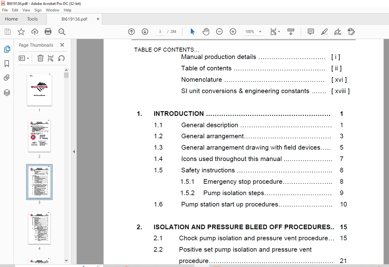
Manual production details [ i ]
Table of contents [ ii ]
Nomenclature [ xvi ]
SI unit conversions & engineering constants [ xviii ]
1 INTRODUCTION 1
1 1 General description 1
1 2 General arrangement 3
1 3 General arrangement drawing with field devices 5
1 4 Icons used throughout this manual 7
1 5 Safety instructions 8
1 5 1 Emergency stop procedure 8
1 5 2 Pump isolation steps 9
1 6 Pump station start up procedures 10
2 ISOLATION AND PRESSURE BLEED OFF PROCEDURES 15
2 1 Chock pump isolation and pressure vent procedure 15
2 2 Positive set pump isolation and pressure vent
procedure 21
2 3 Shearer water pump & 20L Accumulator isolation
and pressure vent procedure 25
2 4 20L Dual accumulator manifold isolation and
pressure vent procedure 28
2 5 Single Chock accumulator manifold assembly
isolation and pressure vent procedure 31
2 6 Positive Set accumulator manifold assembly isolation
and pressure vent procedure 35
BI619136
NEWPAC NUMBER 1 COLLIERY
LONGWALL PUMP STATION
SERVICE & MAINTENANCE MANUAL 2006
iii
3 EMULSION CHOCK PUMP 39
3 1 Pump technical information 39
3 2 Pump components 40
3 3 General description 42
3 4 Pump operation 43
3 5 Unloading control system 45
3 6 Lubrication system 46
3 7 Correction direction of operation 49
3 8 Accumulators 50
3 8 1 General Description 50
3 8 2 Procedure for Lifting 20L Accumulator
Bottle from Pump Station 52
3 9 Servicing and maintenance of pumps 54
3 9 1 Inspection and maintenance requirements 54
3 9 1 1 Daily inspection and maintenance 54
3 9 1 2 Every 3 months – OR – 1000 hours of
operation 54
3 9 1 3 Every 12 months – OR – 5000 hours
of operation inspection to be carried
out by SES service engineer 55
3 9 2 Maintenance procedures 56
3 9 2 1 Pre-maintenance 56
3 9 2 2 Procedure for checking the pump oil
level 57
3 9 2 3 Procedure for adding lubricating oil to
the crankcase 58
BI619136
NEWPAC NUMBER 1 COLLIERY
LONGWALL PUMP STATION
SERVICE & MAINTENANCE MANUAL 2006
iv
3 9 2 4 Procedure for changing lubricating oil 59
3 9 2 5 Procedure for changing oil filter 63
3 9 2 6 Procedure for changing oil seal and
nozzle in oil distributor 67
3 9 2 7 Procedure for removing a pump insert
assembly 71
3 9 2 8 Procedure for the disassembly of a
pump insert 74
3 9 2 9 Pump insert inspection requirements 77
3 9 2 10 Procedure for the reassembly of a
pump insert 78
3 9 2 11 Procedure for the refitting of a pump
insert assembly 80
3 9 2 12 Procedure for the removal of plungers 82
3 9 2 13 Refitting plungers 85
3 9 2 14 Replacing the plunger packing 86
3 9 2 15 Removal of ADM solenoid filter block
assembly 89
3 9 2 16 Replacing ADM solenoid filter block
assembly filter element 91
3 9 2 17 Exchange of safety relief valve 93
3 9 3 Service tools 96
3 9 3 1 Set screws for valve holders of pump
inserts 96
3 9 3 2 Set screw for oil distributor 96
3 9 3 3 Withdrawing device for plungers 96
BI619136
NEWPAC NUMBER 1 COLLIERY
LONGWALL PUMP STATION
SERVICE & MAINTENANCE MANUAL 2006
v
3 9 3 4 Withdrawing device and assembly
mandrel locking pin of crosshead 97
3 9 4 Additional pump information 98
3 9 4 1 Bolt tightening torques 98
3 9 4 2 Grease 99
3 9 4 3 Sealant 99
3 9 5 Trouble shooting guide for Hauhinco
pumps 100
4 POSITIVE SET PRESSURE PUMP 103
4 1 Pump technical information 103
4 2 General description 104
4 3 Pump operation 107
4 4 Unloading control system & 32L accumulator 107
4 5 Lubrication system 109
4 6 Correct direction of operation 111
4 7 Service & maintenance of pumps 112
4 7 1 Inspection and maintenance requirements 112
4 7 1 1 Daily inspections and maintenance 112
4 7 1 2 Every 3 months or 1000 hours of
operation 112
4 7 1 3 Every 12 months or 5000 hours of
operation Inspection to be carried out by
SES service engineer 113
4 7 2 Maintenance procedures 114
4 7 2 1 Pre-maintenance procedures 114
BI619136
NEWPAC NUMBER 1 COLLIERY
LONGWALL PUMP STATION
SERVICE & MAINTENANCE MANUAL 2006
vi
4 7 2 2 Procedure for checking the pump oil
level 115
4 7 2 3 Procedure for adding oil to the
crankcase 116
4 7 2 4 Procedure for changing lubricating oil 116
4 7 2 5 Procedure for changing oil filter 116
4 7 2 6 Procedure for changing nozzle and oil
seal in the oil distributor 117
4 7 2 7 Procedure for removing pump intake
and delivery valves 121
4 7 2 8 Procedure for removing pump insert
assemblies 122
4 7 2 9 Procedure for refitting of pump insert
assemblies 124
4 7 2 10 Procedure for removal of plungers 126
4 7 2 11 Procedure for fitting of plungers 129
4 7 2 12 Replacing the plunger packing 130
4 7 2 13 Procedure for replacing safety valves 133
4 7 3 Additional pump information 136
4 7 3 1 Bolt tightening torques 136
4 7 3 2 Grease 137
4 7 3 3 Sealant 137
4 7 4 Trouble shooting guide for Hauhinco
pumps 138
BI619136
NEWPAC NUMBER 1 COLLIERY
LONGWALL PUMP STATION
SERVICE & MAINTENANCE MANUAL 2006
vii
5 EMULSION STORAGE TANK 140
5 1 Technical information 140
5 2 Emulsion suction outlet ports 141
5 3 Suction Isolation valves 142
5 4 Air breathers 143
5 5 Emulsion tank fluid level viewing port 144
5 6 Drain ports 145
Emulsion temperature transducer
Suction Discharge Bleed point
5 9 Low pressure emulsion sample point 148
5 10 Procedure for taking sample of emulsion from tank 149
5 11 Service and maintenance 152
5 11 1 Inspection and maintenance requirements 152
5 11 1 1 Daily inspections and requirements 152
5 11 1 2 Twelve monthly – OR – every 5000
hours of operation inspection
requirements 152
5 12 Maintenance procedures 153
5 12 1 Suction isolation 153
5 12 2 Procedure changing air breather elements 155
6 EMULSION BOOST PUMP 157
6 1 Emulsion Boost Pump Details 157
6 2 General description 158
6 3 Operation 159
6 4 Emulsion pressure transducer 161
6 5 Boost Pump Start & Stop Buttons 162
BI619136
NEWPAC NUMBER 1 COLLIERY
LONGWALL PUMP STATION
SERVICE & MAINTENANCE MANUAL 2006
viii
6 6 Boost pump maintenance requirements
6 6 1 Inspections and maintenance requirements
6 6 1 1 Weekly inspections
7 PUMP STATION MONITORING SYSTEM 164
7 1 Pump station monitoring system components 164
7 2 General description 167
7 3 Emulsion tank monitoring 167
7 3 1 Emulsion temperature transducer 167
7 4 Chock and positive set pump monitoring 169
7 4 1 Emulsion system pressure transducer 169
7 4 2 Pump lubrication oil pressure switch 170
7 4 3 Lubrication oil pressure transducer 171
7 5 Filtration system monitoring 172
7 5 1 Emulsion return line filter pressure
transmitter & DP switches 172
7 6 Calibration of transducer 173
7 6 1 Lubricating oil pressure transducer
calibration 173
7 6 2 Lube oil temperature transducer calibration 173
8 FILTRATION SYSTEM 174
8 1 General description 174
8 2 Emulsion return line filters 174
8 3 Emulsion inlet filter 176
BI619136
NEWPAC NUMBER 1 COLLIERY
LONGWALL PUMP STATION
SERVICE & MAINTENANCE MANUAL 2006
ix
8 4 Mineral oil filter 177
8 4 1 General description 177
8 5 Shearer water pump inlet filters 178
8 6 Emulsion storage tank air breathers and filtration
magnets 176
8 7 Solenoid pre-control valve filter 181
8 8 Service and maintenance procedures 182
8 8 1 Procedure for changing return line filter
elements and emulsion infill filter element 182
8 8 2 Procedure for changing shearer water inlet
filter element 182
9 MINERAL OIL CONTROL SYSTEM 186
9 1 General description 186
9 2 Levelling cylinders 187
9 3 Load locks 188
9 4 Directional control valves 188
9 5 Diverter ball valve 189
9 6 Remote pendant control system 190
9 6 1 Remote pendant control box 190
9 6 2 Remote pendant control connection panel 191
9 7 Crawler track units 192
9 8 Mineral oil pressure filter 192
9 9 Brake valve 193
9 10 Brake valve hydraulic gauge 193
9 11 Austar Coal Mine hydraulic pump station positioning
procedure 194
BI619136
NEWPAC NUMBER 1 COLLIERY
LONGWALL PUMP STATION
SERVICE & MAINTENANCE MANUAL 2006
x
10 CRAWLER TRACKS ASSEMBLY 197
10 1 Crawler tracks unit specifications 197
10 2 General description 198
10 3 Towing the pump station 200
10 3 Connecting towing unit to the ‘A-frame’ tow
bar 200
10 3 2 Procedure for connecting towing ‘A-frame to
tow vehicle 201
10 3 3 Procedure for freewheeling crawler tracks 213
10 4 Tramming pump station using the crawler track unit 210
10 5 Procedure for replacing oil filling of planetary hubs 213
10 6 Inspection and tensioning crawler tracks 215
10 6 1 Procedure for inspecting and tensioning
crawler tracks 215
11 SHEARER WATER PUMP 219
11 1 Pump technical information 219
11 2 Shearer water pump components 220
11 3 General description 221
11 4 Pump operation 223
11 5 Unloading system 224
11 5 1 General Description 224
11 5 2 Shearer water pump unloader valves 225
11 6 Lubrication system 227
11 7 Correct direction of operation 229
11 8 Transducers for shearer water pump monitoring 230
BI619136
NEWPAC NUMBER 1 COLLIERY
LONGWALL PUMP STATION
SERVICE & MAINTENANCE MANUAL 2006
xi
9 8 1 Delivery pressure transducer 235
9 8 2 Inlet water Pressure transducer 235
9 8 3 Lube oil pressure transducer 235
9 8 4 Lube oil temperature transducer 235
9 8 5 Transducer pressure dampener 236
11 9 Shearer water pump inline inlet water filter 236
11 10 Service and maintenance 237
11 10 1 Inspection and maintenance requirements
for shearer water pump unit 238
11 10 1 1 Daily inspection and maintenance 239
11 10 1 2 Weekly inspection and maintenance 239
11 10 1 3 Every 3 months – OR – 1000 hours of
operation 239
11 10 1 4 Every 12 months – OR – 5000 hours
of operation inspection to be carried
out by SES service engineer 240
11 10 2 Procedure for changing the unloader valve
11 10 3 Maintenance procedures 245
12 MISCELLENOUS ITEMS 246
12 1 Quick release electrical receptacles 246
12 2 Emergency stop buttons 248
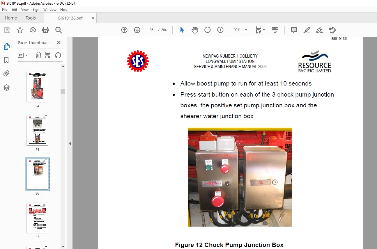
12 3 Start and stop buttons 249
12 3 1 Chock pump & positive set pump 249
12 3 2 Shearer water pump start & stop buttons 250
12 4 Lockable ball valves 251
12 4 1 Face delivery isolation ball valves 251
BI619136
NEWPAC NUMBER 1 COLLIERY
LONGWALL PUMP STATION
SERVICE & MAINTENANCE MANUAL 2006
xii
12 4 2 Chock pump delivery isolation ball valves 253
12 5 Lifting points 255
12 6 Pump station level indicator 256
12 7 Face emulsion return ports 258
12 8 Important signs attached to the pump station 259
13 INSPECTION REQUIREMENTS 260
13 1 Daily inspections 260
13 2 Every 3 months – OR – 1000 hours of operation 261
13 3 Every 6 months 261
13 4 Every 12 months – OR – 5000 hours of operation
Inspection and service to be carried out by SES
service engineer 262
A APPENDIX ‘A’ – NEWPAC SPARE PARTS SCHEDULE
1 Field devices 1 of 4
2 Chock pumps 1 of 4
3 Shearer water pump 1 &2 of 4
4 Chock pumps & shearer water pump 2 of 4
5 General spares 2 of 4
6 Consumables 3 of 4
7 Service exchange items 4 of 4
B APPENDIX ‘B’ – HAUHINCO PUMPS SPARE PARTS LIST No of
PAGES
B 1 Emulsion Chock Pump
Refer Part No Description
BI619136
NEWPAC NUMBER 1 COLLIERY
LONGWALL PUMP STATION
SERVICE & MAINTENANCE MANUAL 2006
xiii
Sect 2 5131162 EHP-3K 200/53 FL (50Hz) 1
Sect 2 5133556 EHP-3K 200 Flange 4
Sect 2 6042600 Spare parts drawing 1
Sect 2 6310176 Oil distributor including filter 2
Sect 2 5132797 Oil pressure control device 2
Sect 2 2321823 Oil pressure control device Condor FF-4 series 1
Sect 2 6208770 Lubrication pump 2
Sect 2 6136249 Bearing cover with flange pump 2
Sect 2 6424287 Complete oil suction filter 1
Sect 2 6426840 Suction pipe for oil pump 1
Sect 2 6343821 Feeding pipe for oil cooler 1
Sect 2 6499155 Return line from oil cooler 1
Sect 2 6230660 Oil cooler 2
Sect 2 2321823 Oil filler/air breather filter 2
Sect 2 2350343 Oil filler/air breather filter 2
Sect 2 6540260 Pump insert with plunger 53 D 3
Sect 2 5118905 Valve cover with spring guide 2
Sect 2 5118867 Valve holder with spring guide 2
Sect 2 6339042 Main control valve H30 2
Sect 2 6256279 3/2 way solenoid valve DN 3 2
Sect 2 6136508 3/2 way-seat-valve DN 3 positive intrinsically
safe 12V
3
Sect 2 6147291 Connection plate 2
Sect 2 6531547 High pressure filter 1
Sect 2 6513158 Pulse-tone accumulator 2 5 l – 400 Bar 2
Sect 2 6344917 Mounting support for pulse-tone accumulator 2
Sect 2 6467768 Pressure gauge connection complete 1
Sect 2 2311763 Pulse-tone accumulator 2
Sect 2 4564596 Hollow screw 1
Sect 2 1720007 Safety valve s 301/108 1
Sect 2 4151852 Safety valve s 301/108 5
BI619136
NEWPAC NUMBER 1 COLLIERY
LONGWALL PUMP STATION
SERVICE & MAINTENANCE MANUAL 2006
xiv
Sect 2 6536352 Pressure connection cover 1
Sect 2 4571657 Coupling half pkd 30 – D 60 – pump side 1
B 2 Positive Set Pressure Pump
Sect 3 5135486 EHP-3K 110FF 7
Sect 3 1720023 Safety Valve S 01/95 1
Sect 3 2310201 2 5L Accumulator 4
Sect 3 2321823 Control Pressure Switch 5
Sect 3 3762254 Lubrication pump 2
Sect 3 4160282 Air vent cock with armatures 1
Sect 3 4571657 Coupling half pkd 30 D60 pump side 1
Sect 3 5100674 Main control valve H300/20 3
Sect 3 5108101 Suction connection with hole G2 2
Sect 3 5118603 Lubrication pump without spur gear 2
Sect 3 5125359 Suction connection – blind 2
Sect 3 6136508 3/2 way-seat valve DN3 positive intrinsically
safe 12V
3
Sect 3 6217486 Oil pressure controller with armatures &
pendant switch
3
Sect 3 6242499 3/2-way-solenoid valve DN3 1
Sect 3 6378218 Complete hollow screw 1
Sect 3 6536344 Pressure connection cover 1
Sect 3 6536395 Intermediate plate DS300 1
Sect 3 6555942 Pump insert with plunger 40D 1
Sect 3 6378226 Hydraulic accumulator with armatures 450Bar 2
B 3 Shearer Water Pump Assembly
Sect 9 5133602 EHP-3K 150/70 flange 1
Sect 9 5133599 EHP 3K 150/70 flange (50Hz) 6
Sect 9 3762254 Lubrication pump 2
Sect 9 5118603 Lubrication pump without spur gear 2
Sect 9 6513360 Pump insert with plunger 70 D 3
BI619136
NEWPAC NUMBER 1 COLLIERY
LONGWALL PUMP STATION
SERVICE & MAINTENANCE MANUAL 2006
xv
Sect 9 5118913 Valve cover with spring guide 2
Sect 9 5118883 Valve Holder with Spring guide 2
Sect 9 5108101 Suction connection with hole G2 2
Sect 9 6518109 Suction connection plate G 2 2
Sect 9 6225748 Intermediate plate 1
Sect 9 6217486 Oil pressure controller with armatures &
pendant switch 3
Sect 9 2321823 Oil pressure control device – Condor ff-4 series 1
Sect 9 6479545 Overflow valve U 504/400 1
Sect 9 6229441 Overflow valve U 540/400 3
Sect 9 6480071 Overflow valve U 504/400 1
Sect 9 4571657 Coupling half pkd 30 D 60 pump side 1
C APPENDIX ‘C’ – FIELD DEVICES
Sect 5 Pump station monitoring system components 3
Sect 5 4152-21B Drawing- pump station field devices 1
D APPENDIX ‘D’ – DBT CRAWLER TRACKS (Size 9)
Sect 8 85300050 Torque hub drawing & bill of materials 2
Sect 8 8700060 Crawler track #9 assembly & bill of materials 3
Sect 8
187000603 Crawler track #9 assembly LH-00 & bill of
materials
5
Sect 8 DBT Technical data sheets 3
Sect 8 8958 028 010 Hydraulic circuit tramming bill of materials 1
Sect 8 8958 028 010 Hydraulic circuit tramming & positioning 1
Sect 8 CT45 Assembly – disassembly manual 12
E APPENDIX ‘E’ PIRTEK HOSE & FITTINGS SCHEDULE
Emulsion hosing circuit 1
Pump accumulator circuit 1
BI619136
NEWPAC NUMBER 1 COLLIERY
LONGWALL PUMP STATION
SERVICE & MAINTENANCE MANUAL 2006
xvi
Pressure and return circuit – mineral oil 1
Tram Motor Circuit 2
Levelling Cylinder Circuit 1
Split flange & ball valve spare parts list 1
F APPENDIX ‘F’ – AMPCONTROL ELECTRICAL CIRCUIT
Pump 1 2181-1021 Local J/Box wiring diagram 1
Pump 2 2181-1031 Local J/Box wiring diagram 1
Pump 3 2181-1041 Local J/Box wiring diagram 1
2181-1061 Emulsion tank marshalling J/Box 1
2181-1071 Pump cart marshalling box 1
G APPENDIX ‘G’ – HYDRAULIC SCHEMATIC
4512-03C Pump station hydraulic schematic 1
H APPENDIX ‘H’ – ENGINEERING DRAWINGS
4152-04H Plan on turning circle 1
4152-21B General arrangement drawing with field devices 1
8708-A Shearer water pump general arrangement 1
I APPENDIX ‘I’ – TOSHIBA 200kW ELECTRIC MOTOR
INSTRUCTION MANUAL
* The Toshiba 200kW electrical motor instruction manual is included in
the form ‘as is’ as supplied by Toshiba The index and contents of the
motor section a separate page numbering, not continuing on from the rest
of the SES Group service manual
(I) 1 0 Instruction Manual No : TMAN000-SCIM-R06 1
(I) 1 0 Receiving Checks 3
I) 1 1 Check on Received Merchandise 3
BI619136
NEWPAC NUMBER 1 COLLIERY
LONGWALL PUMP STATION
SERVICE & MAINTENANCE MANUAL 2006
xvii
I) 1 2 Storage 3
(I) 2 0 Installation 4
I) 2 1 Environment 4
I) 2 2 Foundation 6
I) 2 3 Alignment Procedures 6
(I) 3 0 Start-Up 8
I) 3 1 Check before Start-Up 8
I) 3 2 Checking point during Start-Up 9
(I) 4 0 Disassembly & Reassembly of Motor 11
I) 4 1 Disassembly of Motor 11
I) 4 2 Reassembly of Motor 11
I) 4 3 Grease Requirement 11
(I) 5 0 Maintenance 13
I) 5 1 Routine Maintenance 13
I) 5 2 Knock-Down Examination 14
I) 5 3 Useful Information regarding Operation and
Maintenance
15
(I) 6 0 Troubleshooting and repair 21
(I) 7 0 Storage 25
I) 7 1 Introduction 25
I) 7 2 Storage Area 25
I) 7 3 Storage Maintenance 25
I) 7 4 Storage Inspection Record 27
(I) 8 0 Appendix
Motor Construction Drawing
Bearing Construction Drawing
BI619136
NEWPAC NUMBER 1 COLLIERY
LONGWALL PUMP STATION
SERVICE & MAINTENANCE MANUAL 2006
xviii
J APPENDIX ‘J’ – MATERIAL SAFETY DATA SHEETS
Shell Omala Oil 320
Fuchs RENEP K220
Fuchs Solcenic 2020 4% V/V Emulsion
K APPENDIX ‘K’ – BOOST PUMP DATA
Operating instructions
Arrangement Drawing
DESCRIPTION:
CAT NEWPAC COLLIERY LONGWALL PUMP STATION SERVICE & MAINTENANCE MANUAL 2006 BI619136 – PDF DOWNLOAD
INTRODUCTION
1.1 GENERAL DESCRIPTION
This service and maintenance manual provides an overview of
the equipment installed and specific information pertaining to
the operation and maintenance of the mobile longwall hydraulic
pump station as supplied by Southern Engineering Services Pty
Ltd, in September 2006.
The Newpac Number 1 Colliery’s mobile longwall hydraulic
pump station has been designed to provide the necessary
hydraulic power to efficiently operate the roof supports within a
longwall mine and provide cooling water for the shearer drum
and dust suppression at the coalface.
The pump station is comprised of 3 sleds in total:
• Two (2) off crawler track mounted emulsion sleds
• One (1) off monorail mounted shearer water pump sled
Each Emulsion Sled has the following equipment mounted on
it:
• Three (3) off 3K200/53 chock pump/200 kW motor sets.
• One (1) off 3K110/40 positive set pump/200 kW motor set.
• One (1) off 8,500L stainless steel emulsion storage tank.
S.V 24/03/2025