Cat Rotary Track Drill M-4-SS BLAST HOLE DRILL MAINTENANCE AND OPERATION MANUAL – PDF DOWNLOAD
Original price was: $80.00.$36.95Current price is: $36.95.
Cat Rotary Track Drill M-4-SS BLAST HOLE DRILL MAINTENANCE AND OPERATION MANUAL – PDF DOWNLOAD
Description
Cat Rotary Track Drill M-4-SS BLAST HOLE DRILL MAINTENANCE AND OPERATION MANUAL – PDF DOWNLOAD
DESCRIPTION:
Cat Rotary Track Drill M-4-SS BLAST HOLE DRILL MAINTENANCE AND OPERATION MANUAL – PDF DOWNLOAD
INTRODUCTION
- The Marion Rotary Blast Hole Drill uses a t for the drilling of holes to accept an explosive material. The denotation of the “charge” breaks the rock and loosens the over·
- burden. The rotary bit threads to a drill pipe section that threads to a direct current electric motor on the rotary gearbox on the mast. The rotary gearbox provides torque and rotary speed to the drill bit.
- A roller chain hoist-pull down system, powered by two hydraulic motors, raises and lowers the rotary gearbox and provides a load (or force) to the drill bit.
- The drill air compressor uses a rotary vane impeller to supply air down thru the drill pipe and thru the drill bit. This bailing air cools the bearings in the drill hit and removes the drilled material cuttings from the hole. A leveling system provided on the machine permits the operator to level the machine before each drilling cycle.
- The leveling jacks (cylinders) are controlled in the OPERATION cab with jack location front and rear at each side of the machine. The machine is equipped with an independent propel system which uses a hydraulic motor on each crawler.
- The operator is afforded control of each crawler separately to permit ex· cellent machine maneuverability. The hoist·pull down and propel hydraulic circuits are included in the main system.
- This system is powered by a 200 horsepower motor geared to two variable displacement axial piston pumps.
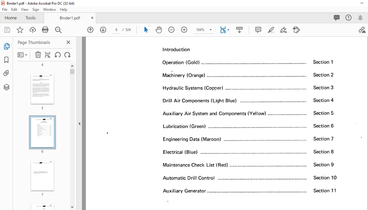
TABLE OF CONTENTS:
Cat Rotary Track Drill M-4-SS BLAST HOLE DRILL MAINTENANCE AND OPERATION MANUAL – PDF DOWNLOAD
Introduction
Operation (Gold) Section 1
Machinery (Orange) Section 2
Hydraulic Systems (Copper) . Section 3
Drill Air Components (Light Blue) Section 4
Auxiliary Air System and Components (Yellow) Section 5
Lubrication (Green) . Section 6
Engineering Data (Maroon) Section 7
Electrical (Blue) . Section 8
Maintenance Check List (Red) Section 9
Automatic Drill Control Section 10
Auxiliary Generator Section 11
Crawlers , 1
Crawler Belt . 1
Adjustment of Crawler Belt . 2
Removing and Replacing Belts . 3
Load Rollers and Top Rollers . 3
Propel Gear Case . 4
Propel Brake
Leveling Jacks ,
Mast and Mast Machinery:
Break Out Tong . 23
Break Out Tool (“Bit Pot”) -•• 24
Winch and Lifting Tackle . 24
Machinery House . 26
House Ventilation System . 27
Propel Control Cable . 28
Installation Procedure for Propel Control Cable
Electri~al Cable Reel:
Start Up and Operating Instructions
C3ble Reel Drum . 33
Collector Ring Assembly . 33
Level Wind Drive Assembly . 33
Amerpulse Dust Collector:
Operating Principles . 38
Solenoid Valve Test
Printed Circuit Timer Test
Final Inspection
High Pressure Drop/Poor Bag Reconditioning . 45
Exhauster Operation Start Up . . . 46
Fan Vvheel Removal . 47
Keep Bearings and Shaft Clean 48
Maintenance 48
Inspect Housing and Wheel . 48
V-Belt Drive Installation . 48
Modular Concept . 1
Main Hydraulic System 1
Accumulator . 2
Pressure Switches . 2
Propel Mode 2
Mode Selection 2
Normal Hoist Pull Down . 3
High Speed Hoist Pull Down Mode
Color Charts (4)
Propel Mode ( Reverse)
Propel Mode (#1 Pump in Neutral, #2 Pump Forward
Propel)(L.H. Crawler)
Hoist Pull Down Mode (Hoist – Normal Speed)
Hoist Pull Down Mode (Hoist – Fast Speed)
Hydrotransmission Valve
Installation . 8
Adjusting . 10
Troubleshooting . 11
Auxiliary Hydraulic System:
Stem Lock Circuit . 13
Stem Rc1ck Cylinder Circuit . 14
Mast Rc1ising and Lowering Cylinders . 14
Leveling Cylinders . 14
Dual Front Jack Leveling System
Steady Guide Circuits
Dust Skirt Circuit
Breakout Tong Circuit . 15
Stem Rack Latch Actuator . 16
Auxiliary Hydraulic System Schematic
Hydraulic System Care and Maintenance:
New Hydraulic Fluid . 17
Change Schedule for Hydraulic Fluid . 18
Hydraulic Filters . 19
Main Hydraulic Control Valves 20
Adjustment of Valves . 20
Staffa Case Leakage . 22
Hose Installation Guide
Recovery
Metal to Metal Contact 25
O-ring Problems . 26
Poor Installation . 26
Installation Preparation . 28
Installation . 29
Back Up Rings . 29
Basic Things to Remember . 31
Modes of Failure . 32
Component Repair and Replacement:
Variable Displacement Axial Piston Pump Assemblies . 33
Main Pump Replacement . 33
Main Pump Installation 34
Minor Repairs, Variable Displacement Pump . 35
Replacement of Pump Shaft Seal . 36
Replacement of Charge Pump and Charge Check Valves . 38
General Parts Identification . 42
Installation Torque Values
Radial Piston Hydraulic Motor
Removing Hydraulic Motor . 46
Valve Assembly Removal and Disassembly . 46
Crank Shaft Removal and Piston Assembly Break Down . 46
Remove Bearings from Motor . 47
Cylinder Head Removal
Crank Case Relief Valve Disassembly
Component Inspection:
Valves, Pistons and Bores . 47
Connecting Rod and Crankshaft . 47
Bearing Inspection . 48
Piston and Valve Seal Rings . 48
0-rings . 48
Shaft Seal 48
Retaining Rings . 48
Socket Cap Screws . 48
Oldham Coupling . 48
Motor Assembly . . 49
BI006459 11111
(Section 3 – Hydraulic Systems cont.) Page
Assembling Valve to Motor . 49
Piston and Connecting Rod Assembling . 50
Connecting Rod & Crank Case Reassembling into Motor Case 50
Setting Crank Shaft End Float . 51
Cylinder Heat Refit . 51
Cross Section of Staffa
Parts Inspection . . . 65
Leveling Jack Cylinder Service Instructions:
Piston Rod Assembly . 68
Head Seals and Bushing Replacement . 68
Piston Seal Replacement . 68
Piston Removal 69
Piston Re-Installation . 69
Installation of Piston Rod Assembly into Cylinder . 69
Jack Cylinder Parts Breakdown . 70
Cross Section of Hydraulic Leveling Jack Cylinder 71
Troubleshooting the Hydraulic Systems:
Charge Pressure Low or Absent . 72
Variable Displacement Pump Does Not Deliver Pressure
or Low Pressure . 72
Hydraulic Motor Does Not Respond to Control , 73
Pump Making Noise . 73
Improper Operation of Motor . 73
Low Auxiliary Hydraulic Pressure . ’73
Mast Will Not Lower , 73
Stem Rack Will Not Lower . 74
Machine Will Not Remain Level, Jack Will Not Hold . 74
Excessive Heat in System . 74
Troubleshooting Guide for Sundstrand:
Introduction 75
Instructions . , 75
Neutral Difficult or Impossible to Find . 76
System Operating Hot . 77
Transmission Operates in One Direction Only . 78
System Response Sluggish . 79
Inspect Control Valve . , . 81
Inspect System Relief Valves . , . 82
Inspect Shuttle Valve . 82
Inspect Charge Check Valves . 83
Check Charge Pressure . 84
Air . 1
Rotary Pressure Joint . 2
Rotary Compressor . . . 2
Cylinder . 2
Cylinder Heads
Rotor and Shaft
Rotor Blades
Shaft Seal
Bearing
Precautions Before Starting . 3
Starting Procedures . 4
Operating Precautions . 4
Intermittent Service Units
Dismantling the Air Compressor . 7
Reassembly . 8
Redoweling . 10
Troubleshooting – Drill Air Compressor . 12
Drill Air Compressor Lubricator . 13
Operation of Lubricator ( Manzel 94 V) . 13
Troubleshooting – Force Feed Lubricator . 14
Uni-Block Flow Divider . 15
Phase Monitor . . . 21
Operating Principals . 21
Drill Air Compressor Cooling System . 26
Anti-Freeze . . . 27
Air Cleaner , 1
Anti-Freezer 1
Anti-Freezer Adjustment . 2
Oil Fog Lubricator . , . 2
Filter Cleaning . : . 2
Filter Pressure Regulator . 3
Air Valves 3
Air Compressor Preventative Maintenance . 4
Air Compressor Operation . 6
Pressure Switch 7
Check Valve . , . 8
Centrifugal Pressure Release (CPR) . 9
CPR Adjustment . 9
CPR Servicing and Removal . 9
Safety Valves 10
Automatic Unloader 11
Air Cylinder Service Instructions , 14
lubrication Fittings . 1
Anti-Friction Bearings . 1
Open Gears . . . 1
Enclosed Gear Cases
Temperature Operation Range . 1
Lubrication Specifications – Greases
Lubrication Specifications – Oils
Special Lubrication Specifications for -5o0c Celcius (-58°F) . 8
Multi-purpose Grease (MPG) 9
Special Instructions for Cold Weather Operation of Drill Air Comp . 10
Hydrostatic Drive Fluid . 11
Specifications . . . 12
MPS Co. Specification – HOF Hydrostatic Drive Fluid . 13
HOF – All Season . 14
M-4-SS
BI006459 11111
(Section 6 – Lubrication cont.) Page
HDF – Summer . 14
HDF – Winter . 14
Approved Products:
Full Approval 14
Conditional Approval . 14
Final Acceptance . 14
Fully Approved Products . 14
Conditionally Approved Products . 14
Special Hydraulic Drive Fluid (HDF) Specifications 15
Hydrostatic Drive Fluid (HOF) Maintenance . 16
Lubrication of Crawler Mount . 18
Lubrication of Rotary Gearbox and Pull Down . 18
Lubrication of Stem Rack
Lubrication Miscellaneous
Semi-Automatic Lubrication for Drill . 21
Replacement of Auto-Lube Components . 21
Liquid Capacities of Machine (U.S. Gallons)
Uni-Block Lubemation System
Operation 26
Displacement and Porting Chart . 27
Basic Lubemation Diagram . 28
Bronze Sleeve Bushings . 1
Flange Bushing 1
Straight Sleeve Bushing . 1
Bushing Life 1
Bushing Replacement . 1
Running Clearance for Bronze Bushings . 2
Installation of Oil and Grease Seals . 4
Split Seals 4
Gear Case Seal . . . . . . . . . . . 5
Installation of Vee Type Grease Seals
Anaerobic Adhesives:
Surface Preparation . 6
Adhesive Removal . . . 6
Adhesive Application . 7
Cured Spline Disassembly 7
Pressure Equipment . 9
Finishing and Recommended Fits . 10
Checking Coupling Alignment . 10
The Solidly Coupled Sets Procedure 10
Recommended Torque Valves . 11
Coup I ing Parts . 13
Installation . 14
Lubrication of Coupling During Assembly , 16
Cap Screw Classes and Tightening Procedures . 17
Turn-of-Nut r”1ethod . , . 17
Torque Method . 17
Engineering Standard 1101-2
Welding Information:
Recommendations for Casting Repairs
Proper Preparation for Welding . 21
Preheat 22
Increase Preheat
Maintain Preheat . ; . 22
Postheat . 22
The Order of Welding . , . 22
Peening 22
Reinforcing Requires Extreme Caution . 23
Postheat Treatment . 23
Material Identification – Marion Material Symbol!> and Major
Component Parts:
Cast Iron Welding Instructions . 24
Table 1 ~ 24
Electrodes . 25
Preheats and Postheats . 25
Material Reference Table . 26
Brush Installation 1
Commutators . . 2
Never Use Emery Cloth or Emery Paper . 2
Proper Lubrication . 3
Feeder Cable . 4
Power Line Grounding . 4
Weekly Electrical Inspection . 13
Weekly Mechanical Inspection . 15
Monthly Electrical Inspection . 25
Monthly Mechanical Inspection . 27
AUTOMATIC DRILL CONTROL
General Description
Marion Automatic Drill Control System
Introduction
Operator Controls
Main Control Panel and Transducers .
System Block Diagram .
Preliminary Measurements .
Power Supplies .
Logic Conditions .
Manual-Drill Set-Up .
Serv,) Amplifier Balance Adjustment .
Gain Adjustrnents .
Auto-Drill Set-Up .
Initial Conditions .
Gain Adjustments
Final Adjustments . 3-5
Propel Set-Up 3-6
Servo Amplifier 4-1
Mother Board/Low Voltage Drop Out Assembly . 4-1
Voltage Regulations . 4-1
Power Amplifiers . 4-4
Pressure Control
Mother Board
Pressure Transducer .
Pressure Transducer Amplifier .
Multiplexer .
Current Control
Current Transducer
Current Transducer Amplifier .
Mother Board
Limit Control
Drill/Propel Logic , 7-1
Propel Control . 7-7
Joystick Option
Meter Assembly . 7-12
Service Kit . , , . , , , .
Preventive, Routine , • ‘. 8-1
A.C. Input Voltage Problems . ,. . , 8-1
Malfunction Flow Chart , 8-2
Card Level Repair . . 8-2
Use of the Model 326 Meter Assembly , 8-2
Factory Repairs , 8-5
$pare Parts and Parts Lists 9-1
Recommended Spare Parts . 9-1
Spare Parts Acquistion 9-1
Parts , 9-1
Sub-Assembly Sheet . 9-1
Control Panel Assembly ., . 9~1
Main Chassis Assembly ,, , 9-1
P.C. Cards . , . 9-1
Appendixes 10-1
Drawing Number Detail . 10-1
Figure Number and Drawing Number Gross Reference • 10-1
P.C. Card Labeling Conventions . 10-1
Engineering Change Orders 11-1
ECO-255A-1 Capacitor Addition, 2/6/73 . 11-1
ECO-255A-2 Wiring Change, 2/6/73 . , , 11-2
ECO-255A-3 Component Change, 6/5/73 , 11-3
ECO-255A-4 P.C. Card (2151) Change, 11/11/75 . 11-4
Cont, ol Panel . . . . . . . 2
Engine . 4
AC Generator . . . . . . . 5
Instruments Mounted in the Control Panel for AC Generator 6
Preparation ;-.nd Inspection Before Starting the Engine
Starting Engine
Functions to Help Start Engine .
Operation .
Starting Engine Without Use of Preheating Device .
Starting Engine With Preheat Device .
Operation After the Engine Starts .
Use of AC Power Source .
Inspection During Operation .
Stoppage .
Emergency Stop .
Precautions on Handling . ; .
Battery .
Maintenance Manual:
General Desicription
Anti-Vibration Rubber
Engine .
Items and Methods of Inspection .
Inspection
Troubles and Countermeasures .
Oil Supply .
Engine Main Part Adjustment Data .
Generator Main Body
Contents and Method of Inspection . 48
Method of Inspection . 49
Main Causes 49
Countermeasures . 49
Brush . 50
Brush Holder and Stud . 51
Bearing . 51
Replacement of Bearing . 51
Insulation 52
Control Panel
Cont’3nts and Methods of Inspection . . . . . 53
Method of Inspection . 53
Trouble and Countermeasure
General Description . . . . . . . 54
AC Generator . . . . . 54
Control Panel 57
Mechanical Disorder . 59
Standards for Adjustment . 59
Battery
Items and Method of Inspection 59
Trouble in Battery . 60
Overcharge . 60
Maximum Current Charging . 61
Insufficient Charge . 61
Volume of Electrolyte . 61
Wrong Installation . 61
Blockade of Exhaust Portion . 62
Freezing of Electrolyte Liquid . 62
CAT ROTARY TRACK DRILL M-4-SS BLAST HOLE DRILL MAINTENANCE AND OPERATION MANUAL – PDF DOWNLOAD:
IMAGES PREVIEW OF THE MANUAL:


PLEASE NOTE:
- This is the same manual used by the dealers to diagnose and troubleshoot your vehicle
- You will be directed to the download page as soon as the purchase is completed. The whole payment and downloading process will take anywhere between 2-5 minutes
- Need any other service / repair / parts manual, please feel free to contact [email protected] . We still have 50,000 manuals unlisted
S.M