Cat Rotary Track Drill MD6420 SKSS-16 Terex Infinity Blasthole Drill Service Manual – PDF DOWNLOAD
Original price was: $80.00.$38.95Current price is: $38.95.
Cat Rotary Track Drill MD6420 SKSS-16 Terex Infinity Blasthole Drill Service Manual – PDF DOWNLOAD
Serial No.1S67A07
SERVICE MANUAL PART NO. 91-A11-421
Description
Cat Rotary Track Drill MD6420 SKSS-16 Terex Infinity Blasthole Drill Service Manual – PDF DOWNLOAD
DESCRIPTION:
Cat Rotary Track Drill MD6420 SKSS-16 Terex Infinity Blasthole Drill Service Manual – PDF DOWNLOAD
Safety Information:
This safety alert symbol indicates important safety messages in this manual. When you see this symbol, carefully read the message that follows and be alert to the possibility of personal injury or property damage.
WARNING:
BEFORE STARTING ENGINE:
- Study Operator and Service Manuals
- Study Engine Operator and Maintenance Manual
- Practice All Safety Precautions
- Make Pre-Operation Check
- Learn Controls Before Operating
It is YOUR responsibility to understand and follow manufacturer’s instructions on machine operation and service, and to observe pertinent safety precautions, laws and regulations.
- Failure to read and understand this manual and all safety, capacity and instruction placards on the machine before operating the unit, constitutes a misuse of the machine.
- It is your responsibility to know the manufacturer’s specific requirements, government regulations, required precautions and any work hazards which may exist.
- You must make these known to all personnel working with the equipment or in the area, so that all may take the necessary and required safety precautions.
- Keep all children, visitors, and untrained personnel away from the equipment. It is also your responsibility to operate your equipment with skill, good judgment, and caution.
- Following recognized safety procedures will help you avoid accidents. Failure to heed these instructions can result in property damage, serious injury or death.
TABLE OF CONTENTS:
Cat Rotary Track Drill MD6420 SKSS-16 Terex Infinity Blasthole Drill Service Manual – PDF DOWNLOAD
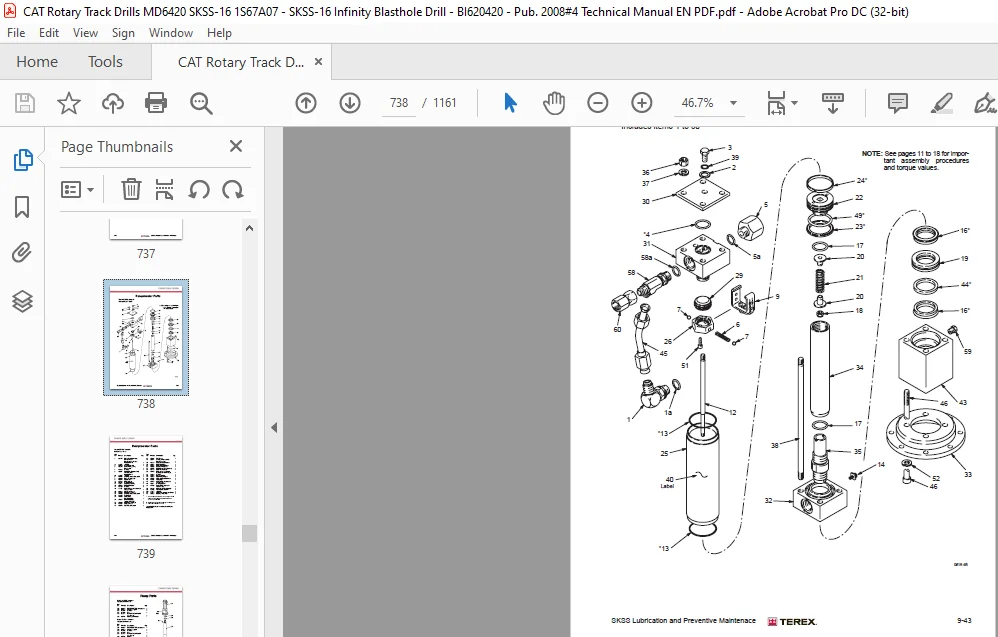
SKSS A07 Service Manual.pdf......................................................  0
	Introduction.................................................................  3
		Safety Information.......................................................  3
		Parts Ordering and Product Support.......................................  4
		Table of Contents........................................................  5
		General Locator.......................................................... 17
	Section 1 - Safety........................................................... 20
		Section 1 Contents....................................................... 22
		Safety................................................................... 23
			Personal Protective Equipment........................................ 23
			Noise................................................................ 23
			Electrical Contact................................................... 23
			Overhead and Buried Utilities........................................ 23
			Contact with Electric Wires.......................................... 24
			Contaminated Air..................................................... 24
			Machine Stability.................................................... 25
			Moving and Rotating Parts............................................ 26
			High Pressure Air or Fluid........................................... 26
			Before Operation..................................................... 26
			During Operation..................................................... 27
			Maintenance.......................................................... 29
			Safety Locator....................................................... 30
	Section 2 - Operator's Cab / Controls........................................ 32
		Section 2 Contents....................................................... 34
		Graphic Symbol Legend.................................................... 35
		Warning Decals........................................................... 39
		Operators Controls and Indicators........................................ 41
			Control Panels....................................................... 41
		Right Hand Control Panel................................................. 42
		Instrument Panel and Circuit Breakers.................................... 43
			Circuit Breakers..................................................... 43
			Light Switches....................................................... 44
			Instrument Panel..................................................... 44
		System Pressure Guage Panel.............................................. 45
		Left Hand Control Panel.................................................. 47
		Foot Control Pedals...................................................... 53
			Cab Foot Controls.................................................... 53
			Thread Grease Switch................................................. 53
			Pipe Safety Arm Override Switch...................................... 53
		Air Conditioner.......................................................... 54
			T8 Series Split System Air Conditioning Manual....................... 54
	Section 3 - Main Frame / Crawlers............................................ 84
		Section 3 Contents....................................................... 86
		Main Frame Repair - General.............................................. 88
			Main Frame Repair.................................................... 88
		Leveling Jacks........................................................... 89
			Leveling Jacks....................................................... 89
			Leveling Jack Cylinders.............................................. 90
		Mast Elevating Cylinders................................................. 91
			Mast Elevating Cylinders............................................. 92
			Remove............................................................... 93
			Repair............................................................... 93
			Replace.............................................................. 93
		Crawler Assembly......................................................... 94
			Crawler Component Repair............................................. 95
		Metric Bolt Torque Specifications........................................ 96
		Track Maintenance........................................................ 97
			Before Operating the Machine......................................... 97
			General Maintenance.................................................. 97
		Track Tension Adjustment................................................. 98
			Hydraulic Tensioner.................................................. 99
			Description..........................................................100
			Nitrogen Tensioner...................................................101
		Hydraulic Tensioner......................................................102
			Repair...............................................................102
		Nitrogen Tensioner Assembly..............................................103
		Nitrogen Tensioner - Fitting Instructions................................104
			Nitrogen Tensioner - Pressure Check..................................106
			Nitrogen Tensioner - Pressure Release................................106
		Track Chain - Separate...................................................107
		Track Chain - Repair.....................................................108
			Track Link - Repair & Replace........................................108
			Track Link - Description.............................................109
		Track Shoes Installation.................................................110
			Track Link Position..................................................110
			Track Shoe - Mounting to Tracsk Chain................................111
		Track Shoe Bolt Torque (Direct Torque Method)............................112
		Track Shoe Bolt Torque (Torque Turn Method)..............................113
		Track Chain and Shoe Installation........................................114
			Track Chain with Shoes...............................................114
			Track Chain & Shoe - Assembly & Installation.........................114
		Final Drive..............................................................116
			Removal from Track Frame.............................................116
			Final Drive Assembly.................................................117
			Final Drive Service..................................................119
			Final Drive Installation.............................................141
		Idler Unit Assembly......................................................142
			Idler Unit - Assembly................................................144
		Idler Unit Removal.......................................................148
			Idler Unit - Removal.................................................148
		Track and Support Rollers................................................150
			General Description..................................................150
			Track Roller - Removal & Disassembly.................................152
			Track and Support Roller - Assembly..................................154
			Track and Support Roller - Test and Install..........................155
		Auxiliary Crane..........................................................157
			Hydraulic Crane (Auxiliary Crane)....................................157
			Load Lift Capacities.................................................157
			Maintenance..........................................................158
	Section 4 - Engine / Drive Train / Compressor................................160
		Section 4 Contents.......................................................162
		Power Group Locator......................................................165
		Cummins Engine...........................................................166
			Engine Fuel System...................................................167
			Construction.........................................................168
			Combo Fuel Filter Head & Pump Manifold...............................169
			FS1006 Fuel Filter with Water Separator..............................169
			Fuel Manifold with Integrated FSO Valve..............................170
			Fuel Connections.....................................................170
			Pre Filters..........................................................171
			Wiring with EFS Power Relay..........................................171
			Pressure and Temperature Sensors.....................................171
			Operation............................................................172
			QST30 Electric Fuel Supply System....................................173
			Oil Reserve Systems..................................................175
			Engine Oil Reserve System (Basic Circuit)............................175
			LED Monitor Readings.................................................176
			Adjustment of Running Oil Level......................................176
			Oil Reserve Basic Circuit............................................177
			Oil Pressure Switch..................................................177
			Oil Reserve System...................................................177
			Troubleshooting......................................................178
			Maintenance..........................................................178
		Engine and Compressor Air Cleaner........................................179
			Engine and Compressor Air Cleaner Service............................180
		Compressor Assembly......................................................183
		Flexible Drive Coupling..................................................184
			Flexible Drive Coupling Service......................................184
		Pump Drive...............................................................186
			Pump Identification..................................................186
			Pump Drive Assembly - Removal and Replacement........................187
		Pump Drive Gearbox.......................................................188
			Pump Drive Gearbox Repair............................................189
			3" Input Shaft Assembly..............................................191
		Hydraulic Pump...........................................................192
			Hydraulic Pumps - Removal and Replacement............................192
		Compressor Installation..................................................193
			Compressor Drive Coupling............................................193
			Compressor Drive Coupling - Removal and Replacement..................197
		Compressor Shaft Seal....................................................199
			Compressor Shaft Seal................................................199
		High Pressure Compressosr................................................202
			Safety...............................................................202
			Description..........................................................205
			Compressed Air Functions.............................................205
		Compressor Oil Circuit...................................................209
			Diagram Legend.......................................................209
			Compressor Oil Circuit - COLD........................................210
			Compressor Oil Circuit - HOT.........................................211
		Compressor Condensation Table............................................212
		Compressor Air Circuit...................................................213
			Compressor Air Circuits - 1475cfm @ 500psi...........................213
		Compressor Functional Description........................................228
		Compressor Operation.....................................................231
			Operation............................................................231
		Compressor Maintenance...................................................234
			General Maintenance..................................................234
			Interstage Tube......................................................236
			Discharge Check Valve................................................237
			Separator/Receiver Tank..............................................238
			Scavenge Line........................................................240
			Compressor Discharge Temperature Gauge, Switch and Sender............241
			Minimum Pressure Valve...............................................242
			Minimum Pressure / Check Valve Maintenance...........................242
			Thermal Bypass Valve.................................................243
			Thermal Bypass Valve Maintenance.....................................244
			Oil Stop Valve.......................................................245
			Compressor Fluid Filter..............................................247
			Changing Filter Elements.............................................248
			Inlet Valve..........................................................249
			Relieving Regulators.................................................251
			Reducing Regulators..................................................254
			System Blowdown Valve................................................256
			Running Blowdown Valve...............................................257
			Running Blowdown Maintenance.........................................258
			Moisture Separator Maintenance.......................................259
			System Air Dryer.....................................................260
			Airodyn Compressed Air Drain Trap Installation.......................261
			Airodyn Compressed Air Drain Trap Operation..........................261
			Airodyn Compressed Air Drain Trap Maintenance........................262
			Auxiliary Regulators.................................................263
			Auxiliary Regulator Maintenance......................................265
			Troubleshooting......................................................267
		Cooler Locator...........................................................270
		Compressor Oil Cooler Assembly...........................................271
		Hydraulic Oil / Radiator Cooler Assembly.................................272
		Coolers Maintenance......................................................273
		Compressor Oil / Hydraulic Oil Cooler Service Manual.....................274
		Radiator Cooler Service Manual...........................................281
	Section 5 - Dust Control System..............................................288
		Dust Control System......................................................291
			Dust Control Systems.................................................291
		Water Injection..........................................................292
			Water Tanks..........................................................292
			Water Tank Top up Soleniod Valve.....................................293
			Water Injection Relief Valve.........................................295
			Water Injection Control..............................................296
			Water Injection Basic Circuit........................................298
		Water Pump...............................................................299
			Pump Specifications..................................................299
			Servicing Instructions...............................................299
			Parts List...........................................................300
			Replacing Piston Cup Seals...........................................301
			Replacing Suction and Discharge Valves...............................302
			Replacing Power End Bearings.........................................303
			Servicing the Wrist Pin Bearings.....................................304
			Fastener Torque Requirements.........................................304
			Recommended Lubricants...............................................305
			Water Pump Motor Repair..............................................305
			Water Injection Hydraulic Control Valve Repair.......................305
			Water Pump Drive Coupling............................................305
			Level and Flow Transducer............................................305
		High Pressure Cleaner....................................................306
			High Pressure Wash down (Motor and Pump).............................306
		Water Injection Valve....................................................312
			Water Injection Ball valve assembly..................................312
			Water Injection Ball valve...........................................312
			Actuator - Installation Operation and Maintenance Manual.............314
			Actuator - Contents..................................................315
			Actuator - Air Connections...........................................316
			Actuator - Installation..............................................317
			Actuator - Dis-assembly..............................................318
			Actuator - Removing Endcaps type ES..................................319
			Actuator - Removing Pistons/Spindle..................................320
			Actuator - Re-assembly guide band and shaft..........................320
			Actuator - Reassembly Pistons........................................321
			Actuator - Re-assembly Endcaps single acting actuators...............322
			Actuator - Re-assembly of springclip and insert......................323
			Actuator - Parts List................................................324
	Section 6 - Mast / Rotary Drive / Pipe Rack..................................326
		Section 6 Contents.......................................................328
		Mast Weldment............................................................329
			Mast Repair..........................................................329
		Mast Assembly............................................................330
			Mast Assembly........................................................330
			Mast Pivot...........................................................331
		Feed Cylinders...........................................................332
			Feed Cylinder - Removal..............................................334
			Feed Cylinder Assembly...............................................336
			Repair...............................................................337
			Installation.........................................................337
		Hoist / Pulldown Cable Adjustment........................................338
			Hosit / Pulldown Cable Adjustment....................................339
			Hoist / Pulldown Cable Replacement...................................342
		Rotary Drive Assembly....................................................343
			Rotary Head Guide Alignment..........................................344
			Rotary Head - Drive System...........................................345
			Rotary Drive - Removal from Mast.....................................346
			Rotary Drive - Installation..........................................346
		Rotary Drive Gearbox.....................................................347
			Rotary Drive Gearbox - Item Listing..................................348
			Rotary Head Bull Shaft Bearing Nut...................................348
			Rotary Drive Gearbox - Repair........................................349
			Air Swivel...........................................................350
		Winch Assembly...........................................................351
			Precautions on the use of Winches....................................351
			Wedge Socket.........................................................353
			Grooved Drums........................................................354
			Plain (Smooth) Drums.................................................354
			Drums - Multiple Layers..............................................354
			Winch Assembly Service...............................................355
			BG8A and BG8B Hydraulic Winch Service Manual.........................356
		Deck Wrench..............................................................387
		H.O.B.O. Wrench..........................................................388
			Breakout System - HOBO...............................................389
			Pipe Safety Arm......................................................389
		Pipe Positioner..........................................................390
		Carousel Pipe Rack.......................................................391
			Major Components.....................................................391
			Rod Handling - Carousel Indexing.....................................392
			Carousel Pipe Rack Assembly..........................................393
			General Information..................................................394
			Pipe Rack Bearings - Removal.........................................394
			Pipe Rack Componetns - Inspection....................................397
			Pipe Rack - Assembly and Installation................................398
			Pipe Rack Roller - Remove and Replace................................399
			Pipe Rack Roller - Disassembly and Assembly..........................400
	Section 7 - Hydraulic Systems................................................402
		Section 7 Contents.......................................................404
		Hydraulic Symbols........................................................407
		Pressure Setting Sequence................................................409
			Pressure Setting Sequence............................................409
		Hydraulic Tank...........................................................411
			Hydraulic Tank.......................................................411
			Return Hydraulic Filters.............................................412
		Main Return and Case Drain Filters.......................................413
			Routine Maintenance..................................................414
			Changing Filter Elements.............................................414
		Main Hydraulic Pumps.....................................................415
			Pump Identification..................................................415
		Right Track, Left Track / Rotation Pumps.................................416
			Hydraulic Piston Pumps - Removal and REplacement.....................416
			AA4VG 180 Hydraulic Pump HD/D Control................................417
			Technical Data.......................................................419
			Port Locations.......................................................423
			Setting Procedure....................................................424
			Charge Pressure, High Pressure, P.O.R. and Zero Position Settings....425
			Set Charge Pressure - 450psi (31 bar)................................425
			Set Crossover Relief (High Pressure) - 5500psi (380 bar).............426
			Set Pressure Override (P.O.R) - 5000psi (345 bar)....................427
			Set Mechanical Zero Position - HD Pump Control.......................428
			Set Hydraulic Zero Position - HD Pump Control........................429
			Removal and Inspection of Charge Pump................................430
			Removal and Installation of Shaft Seal...............................431
			Routine Maintenance..................................................432
		Charge Filter............................................................435
			Routine Maintenance..................................................435
			Changing Filter Elements.............................................435
		Main Pumps Circuit.......................................................437
			Main Pumps Circuit...................................................437
			Rotation/Tram Motor Circuit..........................................438
		Loop Filters.............................................................439
			Routine Maintenance..................................................439
			Changing Filter Elements.............................................442
		Rotation Circuit.........................................................443
			Rotation Circuit.....................................................443
		Rotary Drive Gearbox Motor...............................................445
			Rotary Drive Gearbox Motor - Test and Repair.........................445
			Shaft Seal Replacement...............................................446
			Trouvle Shooting.....................................................448
		Tram Circuit.............................................................450
			Tram Circuit.........................................................450
		Feed and Auxiliary Pump Circuit..........................................452
			Hydraulic Piston Pumps - Removal and Replacement.....................452
			Feed and Auxiliary Functions Pump....................................455
			Repair Instructions..................................................456
			Pump Replacement - Start Up..........................................457
		Hydraulic Systems........................................................459
			Auxiliary and Feed Circuits..........................................459
		Main Control Valves......................................................460
			Valve Stand Assembly.................................................460
		Pilot Control Manifold...................................................461
		Control Valve Assembly...................................................463
			Auxiliary Pump Load Solenoid Valve...................................463
		Hydraulic Feed Circuit...................................................469
		MP22 Valve - Hoist and Pulldown Control..................................471
		Feed Valve Assembly......................................................474
		Holdback Control.........................................................477
		Jack Control and Mast Elevating Circuit..................................478
			Jack Control and Mast Elevating Circuit..............................479
		MP18 Valve - Jack and Mast Raise Valve...................................480
		Counterbalance Valves....................................................482
			Counterbalance Valve Adjustment......................................482
		Leveling Jack Cylinders..................................................483
			Counterbalance Valve Test Procedure..................................484
		Mast Elevating Cylinders.................................................485
			Counterbalance Valve Test Procedure..................................486
		Auxiliary Functions Circuit..............................................487
			Auxiliary Functions Circuit..........................................487
		4WE6 - Aux. Functions and Mast Valves....................................489
			Repair Kits..........................................................491
			Exploded View of 4WE6................................................492
		Hydraulic Operated Breakout Wrench.......................................493
			Setting of HOBO Sequence Valves......................................494
		Hydraulic Systems........................................................495
			Pipe Safety Arm......................................................496
			Hydraulic Gear Pumps - Removal and Relpacement.......................497
			Hydraulic Gear Pumps - Repair........................................497
			Hydraulic Gear Pumps - Shaft Seal Removal and Replacement............498
		Cooler Fan Circuit.......................................................500
			Fan Motor Circuit....................................................500
		Cooler Fan Motor.........................................................503
			Hydraulic Motor......................................................503
		Hydraulic Thermostatic Valve.............................................507
			Hydraulic Cooler - Thermal Valve.....................................507
		Central Lube.............................................................508
			Hydraulic Circuit....................................................509
		Air Conditioner Compressor Drive Circuit.................................510
		Air Conditioner Drive Motor..............................................511
			Design...............................................................511
			Operational Check....................................................511
			Shaft Seal Replacement...............................................512
			Screw Tightening Torque..............................................512
			Gear Backlash........................................................512
			Specifications.......................................................512
			Parts List...........................................................513
		Water Injection / Foam Injection Circuit.................................514
			Water Injection / Foam Injection Valve...............................515
		Water Injection / Foam Injection Valve...................................517
			Introduciton.........................................................517
			Valve Stack Assembly.................................................518
			Segment Alterations..................................................519
			Pulsar Solenoid Removal and Plug.....................................521
			Recommended Test Stand...............................................522
			Final Stack Adjustment...............................................525
			Assembly Drawing - VBL Bypass Inlet Segment Parts List...............531
			Assembly Drawing - VPL Work Segment Parts List.......................533
		Water Pump Motor.........................................................535
			Water Pump Motor Repair Information..................................535
			Shaft Seal Repair....................................................536
		Foam Injection Unit......................................................539
		Hydraulic Cylinder Repair................................................540
			General Information..................................................541
			H Head...............................................................543
			N Head...............................................................544
			Z Head...............................................................545
			Z Head ( Two Piece)..................................................546
			K Head...............................................................547
			M Head...............................................................548
			Z Piston.............................................................549
			Z Piston (Threaded)..................................................550
			H & K Piston.........................................................551
			M Piston.............................................................552
			N Piston.............................................................555
	Section 8 - Electrical Components............................................556
		Section 8 Contents.......................................................558
		Electrical Locator.......................................................559
			Electrical Locator Parts List........................................561
		Jump Starting............................................................562
		Batteries................................................................564
		Welding Precautions......................................................565
		Vigilante Guide..........................................................566
			Important Information................................................566
			PLC..................................................................567
			EEPROM...............................................................568
			Output Card..........................................................569
			Touchscreen..........................................................570
			Laser Depth System...................................................571
			Safety Instructions & Precautions....................................572
			Pipe in Hole Detection...............................................573
			Distance Meter.......................................................573
			Start Up and Shut Down...............................................574
			Hydraulic Function Enable............................................574
			Alarms...............................................................574
			Solenoid Control.....................................................575
			Auto Lube............................................................578
			Hammer Oiler System..................................................578
			Gauges...............................................................579
			Pressure Transducer..................................................579
			Level Transducer.....................................................579
			Hammer Oil Level Transducer..........................................579
			Temperature Transducer...............................................580
			Water Flow Transducer................................................582
			Inclinometers........................................................583
			Head Speed Module....................................................584
			Level Switches.......................................................585
			Dust Suppression.....................................................585
			Turkey Spray.........................................................585
			Water Suppression Tank - Top Up......................................585
		Vigilante System Component Information...................................586
			Head Speed Module....................................................586
			Rotary Head Speed Flowmeter..........................................588
			Inclinometer.........................................................592
			Ladder Prox Switch...................................................595
			LDM 40 A Laser.......................................................596
			Level Switches - Capacitive Level Switch (Hydraulic Oil Level).......608
			Radiator Level Switch................................................612
			Level Transducer - Electronic Level Sensor...........................616
			Hammer Oil Level Transducer..........................................626
			Pressure Transducer - Combined Pressure Sensor.......................628
			Temperature Transducer - Control Monitor for Temperature Sensors.....637
			Temperature Sensor...................................................649
			Water Flow Transducer - Flow Sensor Analog...........................650
			Water Control Module.................................................664
			Rod Counter Switch...................................................693
			Remote Fuel Level Display............................................694
	Section 9 - Lubrication and Preventive Maintenance...........................696
		Section 9 Contents.......................................................698
		Central Lube System......................................................700
			Hydraulic Control Schematic..........................................701
			Auto Lube............................................................701
			Central Lube Pump Module.............................................705
			Central Lube Pump....................................................718
		Hammer Oiler Tank Assembly...............................................744
		Hammer Oil Circuit.......................................................745
		Hammer Oil System........................................................746
			Air Service Unit Components..........................................746
			Filter Regulator.....................................................747
			Air Line Oiler.......................................................748
			Fire Ball 425 Pump - Instructions....................................749
		Pipe Thread Lubricator...................................................766
			Air Service Unit.....................................................766
			Filter Regulator.....................................................767
			Air Line Lubricator..................................................768
			Pipe Thread Pump.....................................................769
		Filter Locator...........................................................777
		Lubrication General......................................................779
			Equipment Lubrication................................................779
			Care of Lubrication Points...........................................779
		Torque Valves for Split Flange Connections...............................780
		Lubrication and Preventive Maintenance...................................783
			Safety...............................................................783
			Track Gear...........................................................783
			Engine Maintenance...................................................785
			Air Cleaners.........................................................786
			Air Filter Elements..................................................786
			Alternator Maintenance...............................................786
			Pump Drive and Drive Shaft Maintenance...............................787
			Compressor Maintenance...............................................787
			Cooler Packs.........................................................787
			A-Frame and Pivot Point Maintenance..................................789
			Pull Down and Hoist Ropes and Sheaves Maintenance....................789
			Hydraulic System Maintenance.........................................791
			Hydraulic Maintenance................................................791
			Water Pump Maintenance...............................................791
			Cab Maintenance......................................................791
			Air Conditioner Maintenance..........................................793
			Battery Maintenance..................................................793
			Lubrication System Maintenance.......................................793
			Fire Suppression Maintenance.........................................793
		Lubrication and Maintenance Chart 250hr..................................795
		Lubrication and Maintenance Chart 500hr..................................805
		Lubrication and Maintenance Chart 1000hr.................................816
		Lubrication and Maintenance Chart 2000hr.................................827
		Lubricant Specifications.................................................839
			Hydraulic System.....................................................839
			Hydraulic Tank Capacity..............................................839
			Compressor Lubrication...............................................840
			Compressor Lubricant Specifications..................................840
			Lubricating Grease...................................................841
			Gear Lubricant.......................................................841
			Scheduled Oil Sampling Analysis......................................841
CAT ROTARY TRACK DRILL MD6420 SKSS-16 TEREX INFINITY BLASTHOLE DRILL SERVICE MANUAL – PDF DOWNLOAD:
IMAGES PREVIEW OF THE MANUAL:


PLEASE NOTE:
- This is the same manual used by the dealers to diagnose and troubleshoot your vehicle
- You will be directed to the download page as soon as the purchase is completed. The whole payment and downloading process will take anywhere between 2-5 minutes
- Need any other service / repair / parts manual, please feel free to contact [email protected] . We still have 50,000 manuals unlisted
S.M