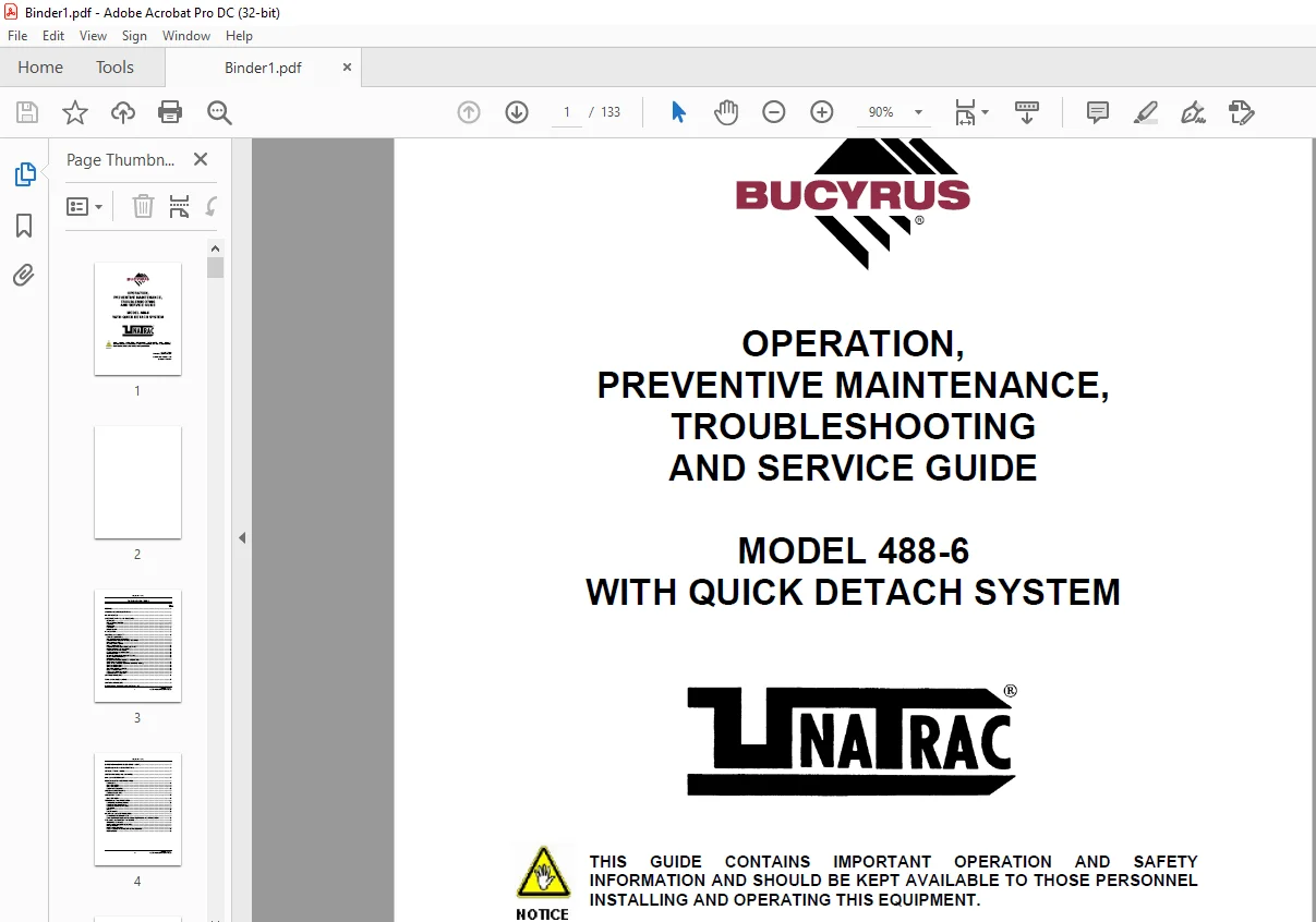
CAT Scoop 488-6 WITH QUICK DETACH SYSTEM OPERATION, PREVENTIVE MAINTENANCE, TROUBLESHOOTING & SERVICE GUIDE MANUAL A6474X240
$26.95
CAT Scoop 488-6 WITH QUICK DETACH SYSTEM OPERATION, PREVENTIVE MAINTENANCE, TROUBLESHOOTING & SERVICE GUIDE MANUAL A6474X240 – PDF DOWNLOAD
Description
CAT Scoop 488-6 WITH QUICK DETACH SYSTEM OPERATION, PREVENTIVE MAINTENANCE, TROUBLESHOOTING & SERVICE GUIDE MANUAL A6474X240 – PDF DOWNLOAD
FILE DETAILS:
CAT Scoop 488-6 WITH QUICK DETACH SYSTEM OPERATION, PREVENTIVE MAINTENANCE, TROUBLESHOOTING & SERVICE GUIDE MANUAL A6474X240 – PDF DOWNLOAD
Language : English
Pages : 133
Downloadable : Yes
File Type : PDF
IMAGES PREVIEW OF THE MANUAL:
DESCRIPTION:
CAT Scoop 488-6 WITH QUICK DETACH SYSTEM OPERATION, PREVENTIVE MAINTENANCE, TROUBLESHOOTING & SERVICE GUIDE MANUAL A6474X240 – PDF DOWNLOAD
PREFACE:
This manual is intended to provide GENERAL product information for the Model
488 Series UN-A-TRAC®. The illustrations, descriptions and procedures contained in
this publication apply only to this Model 488 UN-A-TRAC®. Bucyrus America, Inc. reserves the
right to revise models and designs without prior notice.
- This Model 488 UN-A-TRAC® was manufactured under the guidelines, procedures and
requirements of the U. S. Federal Coal Mine Health and Safety Act, Code of Federal Regulations,
Title 30, Chapter 1, Subpart 0, Part 75 for underground coal mines, and other
applicable non-U. S. regulatory agency standards. - At the completion of the manufacturing process, this Model 488 UN-A-TRAC® was issued the
appropriate approval numbers and nameplates indicating it met the technical requirements of
these regulatory agencies. Any change to the design or structure of this Model 488
UN-A-TRAC®, without the consent of Bucyrus America, Inc., and these regulatory
agencies, or any repair or replacement of parts contrary to Bucyrus America’s instructions,
may invalidate these approvals and render this Model 488 UN-A-TRAC® unsafe to operate. - Strict compliance with all Federal and State Mining laws, regulations and practices
regarding the safe operation and maintenance of underground mining equipment and strict adherence
to the instructions in this manual is necessary for the personal safety of those working on or
around this Model 488 UN-A-TRAC®. - While this manual attempts to anticipate the most important operations and maintenance needs for
this Model 488 UN-A-TRAC®, unforeseen circumstances may arise that have not been addressed in
this manual. If any concerns or questions arise, please contact your Bucyrus America
Service Representative immediately. - This work contains information protected under trade secret and other intellectual property laws,
and is protected under the U. S. Copyright Act of 1976, as amended. This work is
provided under license and the license is non- transferable. Distribution and
access is limited only to authorized personnel. Disclosure, reproduction, distribution or
unauthorized use may be a violation of federal and state laws and may subject the unauthorized user
to criminal liability.
SAFETY PRECAUTIONS AND GUIDELINES
OVERVIEW
- Before you operate, maintain or in any other way, use this unit –
- READ and STUDY this guide. KNOW how to safely use the unit’s controls and what you must do for
safe maintenance. - ALWAYS wear or use the proper safety items required for your personal protection.
- If you have ANY QUESTIONS about the safe use or maintenance of this unit:
- ASK YOUR SUPERVISOR – NEVER GUESS – ALWAYS CHECK
PRE-START INSPECTION:
- Read this entire guide BEFORE attempting to operate this unit. You should be familiar with the
controls and their functions before the unit is energized. - INSPECT your machine by doing a pre-operational inspection. Have any malfunctioning,
broken or missing parts corrected or replaced before use. - VERIFY that all maintenance has been performed.
- VERIFY that all the instruction and safety labels are in place and readable. These are as
important as any other equipment on the machine. - CLEAN any foreign material from the operator’s compartment.
- THIS Model 488 Series UN-A-TRAC® was shipped from the factory equipped with a protective canopy.
- This canopy MUST be securely in place before operating the unit.
STARTING:
- DO NOT operate any levers or pedals from outside the operator’s compartment to keep the machine
from hitting you or other personnel. - FOLLOW the instructions in the STARTING PROCEDURES section of this guide (page 23). DO NOT operate
any levers or pedals if anyone is in the Hazard Zone (page 21). - BE familiar with the operation of the tape switches and be prepared for the sudden stop when the
tape switches are struck.
OPERATING:
- ALWAYS make sure that no person or obstruction is in your line of travel BEFORE starting the unit
into motion or in the articulation area when steering the unit. - NEVER climb onto, or climb out of the machine while it is in motion.
- DO NOT operate the machine with any part of your body outside of the operator’s compartment in
order prevent body parts from being crushed between the machine and objects outside.
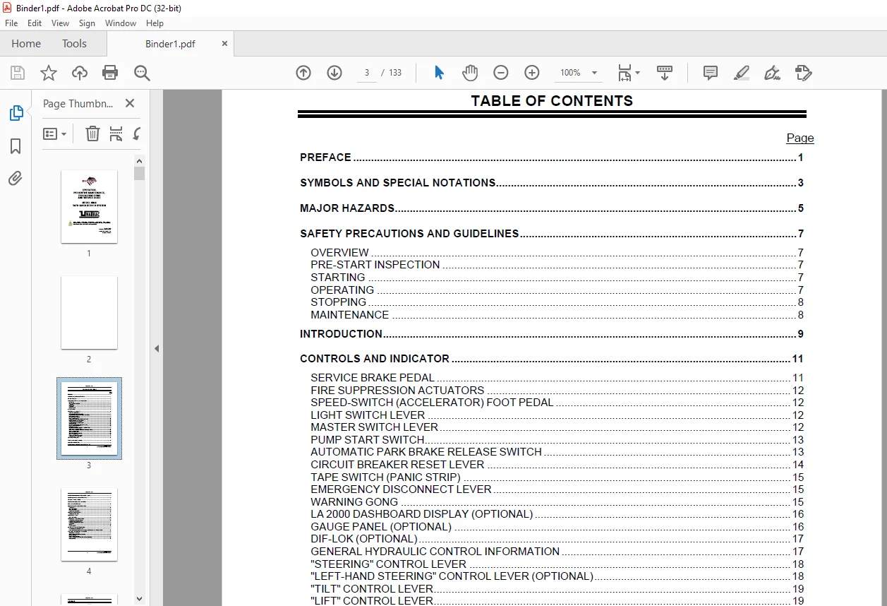
TABLE OF CONTENTS:
CAT Scoop 488-6 WITH QUICK DETACH SYSTEM OPERATION, PREVENTIVE MAINTENANCE, TROUBLESHOOTING & SERVICE GUIDE MANUAL A6474X240 – PDF DOWNLOAD
PREFACE 1
SYMBOLS AND SPECIAL NOTATIONS 3
MAJOR HAZARDS 5
SAFETY PRECAUTIONS AND GUIDELINES 7
OVERVIEW 7
PRE-START INSPECTION 7
STARTING 7
OPERATING 7
STOPPING 8
MAINTENANCE 8
INTRODUCTION 9
CONTROLS AND INDICATOR 11
SERVICE BRAKE PEDAL 11
FIRE SUPPRESSION ACTUATORS 12
SPEED-SWITCH (ACCELERATOR) FOOT PEDAL 12
LIGHT SWITCH LEVER 12
MASTER SWITCH LEVER 12
PUMP START SWITCH 13
AUTOMATIC PARK BRAKE RELEASE SWITCH 13
CIRCUIT BREAKER RESET LEVER 14
TAPE SWITCH (PANIC STRIP) 15
EMERGENCY DISCONNECT LEVER 15
WARNING GONG 15
LA 2000 DASHBOARD DISPLAY (OPTIONAL) 16
GAUGE PANEL (OPTIONAL) 16
DIF-LOK (OPTIONAL) 17
GENERAL HYDRAULIC CONTROL INFORMATION 17
“STEERING” CONTROL LEVER 18
“LEFT-HAND STEERING” CONTROL LEVER (OPTIONAL) 18
“TILT” CONTROL LEVER 19
“LIFT” CONTROL LEVER 19
“EJECTOR” CONTROL LEVER 19
“QDS” CONTROL LEVER 19
“PTO / BATT” CONTROL LEVER 20
BRAKE RELEASE HAND PUMP 20
STARTING PROCEDURE 23
TOWING A DISABLED MACHINE 27
SHUTDOWN PROCEDURE 29
BATTERY CHANGE PROCEDURE (VERTICAL LIFT) 32
BATTERY CHANGE PROCEDURE (GROUND LEVEL) 37
GENERAL MAINTENANCE INSTRUCTIONS 45
CRITICAL TORQUE VALUES 47
LUBRICANTS, FLUIDS AND CAPACITIES 47
MAINTENANCE CHECK LIST 49
PERIODIC MAINTENANCE PROCEDURES 51
EVERY SHIFT 51
ONCE PER WEEK 50
ONCE PER MONTH 60
EVERY THREE MONTHS 62
LUBRICANT SPECIFICATIONS 65
APPROVED SUPPLIERS 65
LUBRICATION CHART 67
ONCE PER WEEK 67
TROUBLESHOOTING PROCEDURES 69
HYDRAULIC SYSTEM (GENERAL) 70
BRAKES (SERVICE) WET DISC 71
BRAKES (AUTOMATIC WET DISC) 72
CYLINDERS 72
PUMPS 73
RELIEF VALVES 75
MAJOR MAINTENANCE PROCEDURES 77
CONTACTOR TIP REPLACEMENT 77
DRIVE MOTOR/GEARBOX (SPEED REDUCER) REMOVAL AND REPLACEMENT 78
TIRE/WHEEL INSTALLATION PROCEDURE 81
TIRE/WHEEL STRESSES 81
WHEEL MOUNTING ARRANGEMENTS 81
PROBLEM AREAS 81
WHEEL MOUNTING TIPS 82
RECOMMENDED WHEEL MOUNTING PROCEDURES: 83
PRECAUTIONS: 83
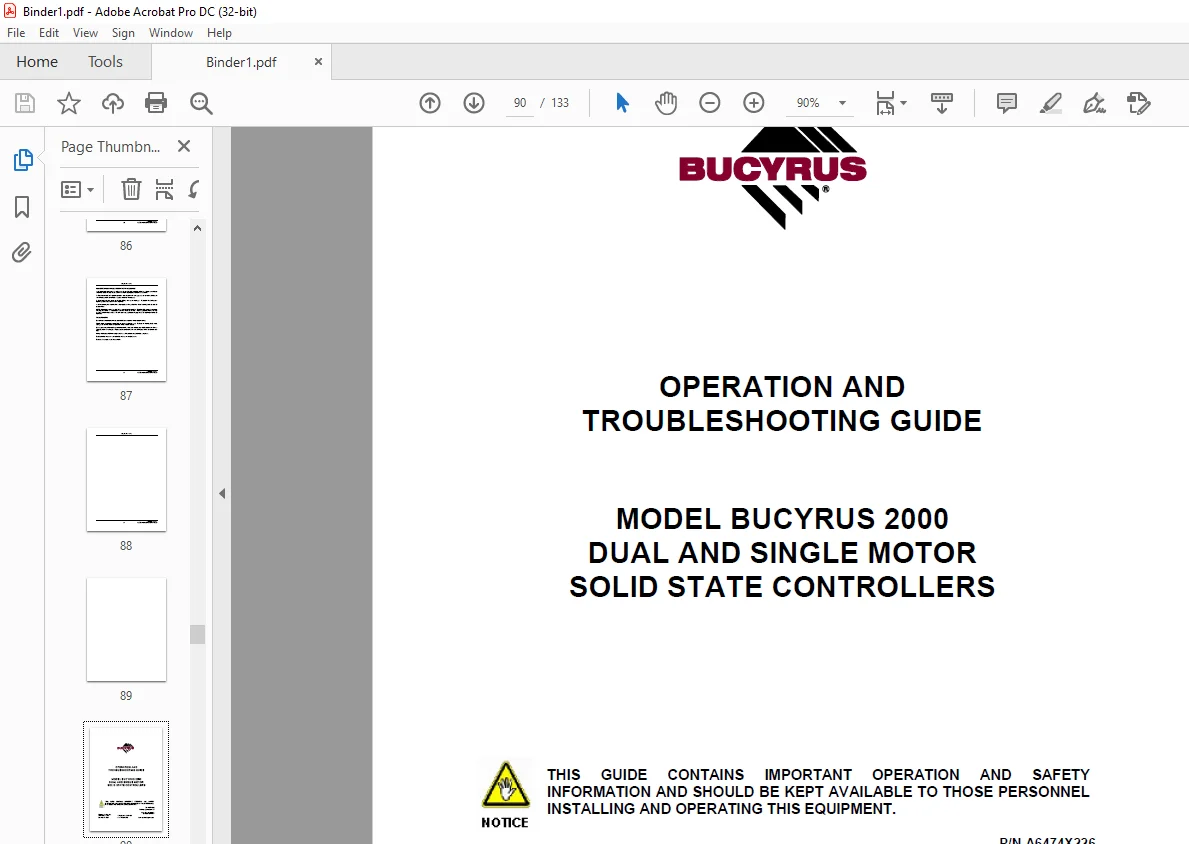
2. CAT Scoop BUCYRUS 2000 DUAL & SINGLE MOTOR SOLID STATE CONTROLLERS OPERATION & TROUBLESHOOTING GUIDE MANUAL PN A6474X226
PREFACE 2
SYMBOLS AND SPECIAL NOTATIONS 3
MAJOR HAZARDS 5
SAFETY PRECAUTIONS AND GUIDELINES 6
OVERVIEW 6
MAINTENANCE 6
INTRODUCTION 7
BUCYRUS 2000: INNOVATIVE SPEED CONTROL BY BUCYRUS AMERICA, INC 7
GENERAL SPECIFICATIONS 12
FAIL-SAFE OPERATION WILL INCLUDE THE FOLLOWING: 12
DESCRIPTION OF FEATURES 13
BUCYRUS 2000 MOTOR CONTROLLER CONSIST OF: 13
BUCYRUS 2000 MOTOR IGBT PANEL (POWER CONNECTIONS) 13
MICROPROCESSOR BASED LOGIC CARD (CONTROL INPUTS) 13
CONFIGURATION JUMPER TABLE 15
OPTIONAL DASHBOARD DISPLAY FEATURES (SEE FIGURE 9) 15
FAULT MESSAGE CHART 16
OPTIONAL HAND HELD DIAGNOSTICS/CALIBRATOR UNIT 18
PERSONALITY ADJUSTMENT PROCEDURE 19
TRACTION PERSONALITIES (CONTROLLER ADJUSTMENTS) 19
TRACTION STATUS DISPLAY 21
TRACTION TEST DISPLAY 23
TRACTION BDI DISPLAY 24
ERROR CODE LEGEND (STATUS DISPLAY) 25
TROUBLESHOOTING 26
IGBTMEASUREMENTS 27
INDIVIDUAL IGBT MEASUREMENTS 28
DIODEMEASUREMENTS 29
DIODEMEASUREMENTS 30
PANEL MEASUREMENTS 31
DRIVER MEASUREMENTS 32
IGBT DUAL MOTOR PANEL, FIGURE 16 34
IGBT SINGLEMOTOR PANEL,FIGURE 17 35
IGBT HEAT SINK ASSEMBLY, FIGURE 18 36
SINGLE MOTOR PANEL HARNESS ASSEMBLY, FIGURE 19 37
DUAL MOTOR PANEL HARNESS ASSEMBLY, FIGURE 20 38
DASHBOARD DISPLAY, FIGURE 21 39
DUAL “Y” HARNESS, FIGURE 22 40
HARNESS FOR DASHBOARD DISPLAY, FIGURE 23 41
CALIBRATOR UNIT, FIGURE 24 42
BUCYRUS 2000 PUMPMOTOR SHUNT, FIGURE 25 42
BUCYRUS 2000 PANELWIRING HARNESS, FIGURE 26 43
Contact us: [email protected]
S.V