CAT Shearer EL2000 Operation & Maintenance Manual BI628443 – PDF DOWNLOAD
$28.95
CAT Shearer EL2000 Operation & Maintenance Manual BI628443 – PDF DOWNLOAD
Description
CAT Shearer EL2000 Operation & Maintenance Manual BI628443 – PDF DOWNLOAD
FILE DETAILS:
CAT Shearer EL2000 Operation & Maintenance Manual BI628443 – PDF DOWNLOAD
Language : English
Pages : 320
Downloadable : Yes
File Type : PDF
IMAGES PREVIEW OF THE MANUAL:
DESCRIPTION:
CAT Shearer EL2000 Operation & Maintenance Manual BI628443 – PDF DOWNLOAD
This chapter contains important information which will simplify the
use of this manual for you. In addition it includes information about
the structure of the manual and on the characters and symbols
used.
Before starting work:
correct operating manual:
If you use an operating manual which has not been written for your
machine type, you will endanger yourself and others.
Ensure that the serial number on you machine corresponds with the
following :
Shearer EL 2000
Ident. no.: EL2000-034
The operating manual must be accessible at all times to all persons
working on, or with, this shearer.
If your manual is no longer complete, has become illegible or damaged,
send for a replacement immediately.
Who is this operating manual intended for?
This operating manual is intended for all persons working with or on
the shearer.
All persons working with the shearer must have read this manual.
This includes persons:
- responsible for transport
- carrying out the drivage
- carrying out erection / dismantling
- operating the shearer
- eliminating faults
- carrying out routine work on the face
- carrying out maintenance operations
- carrying out repairs
TABLE OF CONTENTS:
CAT Shearer EL2000 Operation & Maintenance Manual BI628443 – PDF DOWNLOAD
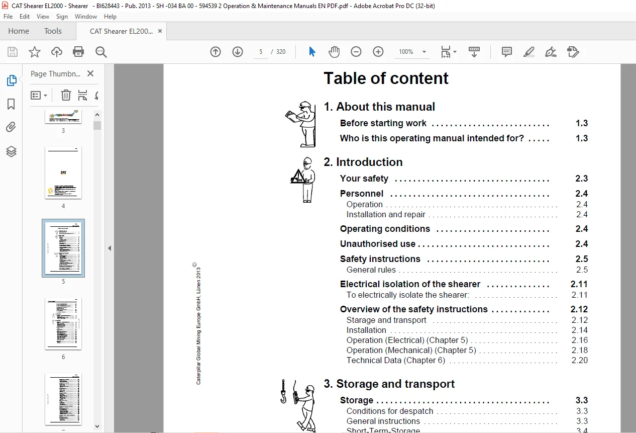
1 About this manual
Before starting work 1 3
Who is this operating manual intended for? 1 3
2 Introduction
Your safety 2 3
Personnel 2 4
Operation 2 4
Installation and repair 2 4
Operating conditions 2 4
Unauthorised use 2 4
Safety instructions 2 5
General rules 2 5
Electrical isolation of the shearer 2 11
To electrically isolate the shearer: 2 11
Overview of the safety instructions 2 12
Starage and transport 2 12
Installation 2 14
Operation (Electrical) (Chapter 5) 2 16
Operation (Mechanical) (Chapter 5) 2 18
Technical Data (Chapter 6) 2 20
3 Storage and transport
Storage 3 3
Conditions for despatch 3 3
General instructions 3 3
Short-Term-Storage 3 4
Long-Term-Storage 3 4
Storing used equipment 3 4
Transport 3 6
Load Units, Dimensions and Weights 3 6
Before Transport 3 6
Transport of the Components 3 6
Transporting The Machine Underground 3 7
Cutting Drum Removal 3 10
Ranging Arm Hydraulic Cylinder Removal 3 12
EL58B Ranging Arm Motor Removal 3 13
EL62F Ranging Arm Removal 3 14
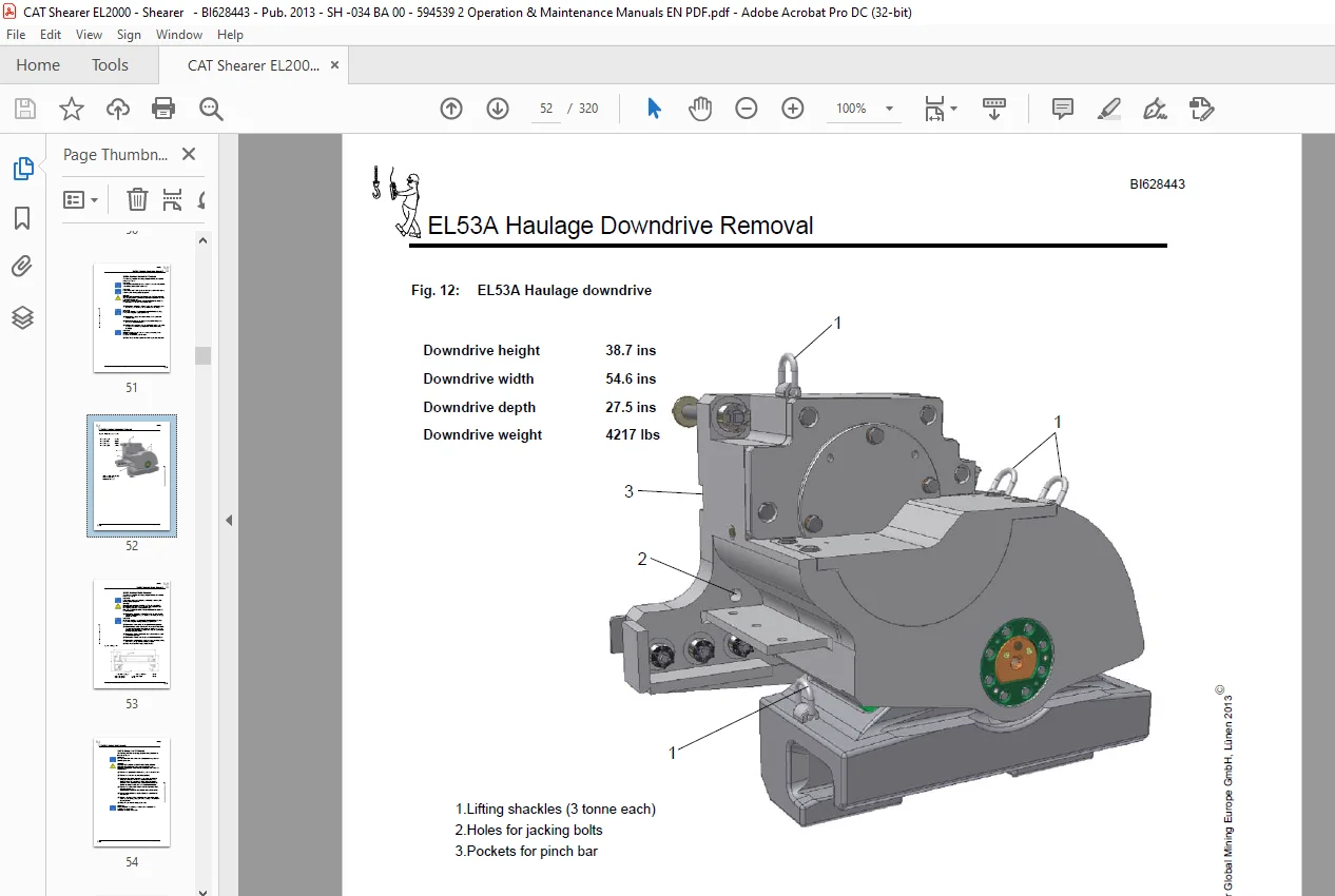
EL53A Haulage Downdrive Removal 3 15
Caterpillar Global Mining Europe GmbH, Lünen 2013E
BI628443
Table of content
Shearer EL 2000
EL55C Haulage Motor Removal 3 17
EL57B Haulage Unit Removal 3 18
EL56BN Hydraulic Pump Motor Removal 3 20
Hydraulic Reservoir Removal 3 21
Control Box (EL49A),
Power Box (EL48A) Removal 3 22
EL45A Mainframe 3 24
Face Side Shoe Removal 3 25
4 Installation
Installation of the machine underground 4 3
Greasing 4 4
Oil and Fluid filling 4 4
Commissioning the Haulage System 4 6
Fault Diagnosis and Repair 4 6
5 Operation
Introduction To Electrical Equipment 5 3
General 5 3
Electrical control boxes 5 4
Electric motor driven units 5 4
Hydraulically actuated units 5 5
Other electrical equipment 5 6
EL49A Control box 5 9
General 5 9
EL48A Power box 5 13
General 5 13
Operator Controls (electrical) 5 15
Main Switch Handle 5 17
Machine ‘START’ pushbutton 5 17
Pilot ‘TEST’ pushbutton 5 17
Machine ‘START/TEST’ pushbutton 5 17
Machine ‘START RUN’ pushbutton 5 17
Motor START / STOP pushbutton 5 18
Motors ‘STOP’ pushbutton 5 18
Stop / Emergency stop lever 5 18
Keypad 5 18
Radio control selection 5 18
Pilot circuit 5 19
General 5 19
Pilot circuit 5 20
Caterpillar Global Mining Europe GmbH, Lünen 2013E
BI628443
Table of content
Doc no : SHEL2000-034 BA 00 VPSP / 01
Electrical power distribution 5 23
General 5 23
Main power distribution 5 24
Control power distribution 5 25
EL58B Ranging Arm Motors 5 27
General 5 28
System operation 5 29
Motor start circuits 5 31
Quill Shaft Removal Procedure 5 32
Lubrication 5 32
EL56BN Pump Motor 5 33
General 5 33
System operation 5 34
Motor start circuit 5 35
Lubrication 5 36
EL55C Haulage Motor 5 37
General 5 37
Motor operation 5 38
Motor start circuit 5 38
Motor removal procedure 5 38
Quill Shaft 5 41
Removal Procedure 5 42
Assembly Procedure 5 46
Lubrication 5 48
Radio Control System 5 49
General 5 49
Key Features 5 49
System operation 5 49
Transmitter 5 50
Radio Receiver Unit 5 53
Hydraulic Functions (electrical control) 5 54
General 5 54
Haulage System (AC drive) 5 58
General Description 5 58
Basic System Operation 5 58
Haulage Circuit Description 5 59
Introduction To Inverter Drive 5 61
Multiple Drives And Motors 5 65
COMPACT Display Module and Keypad 5 67
Configuration Switches 5 69
Component Location (quick reference guide) 5 71
General 5 71
Maintenance (electrical) 5 77
Fault diagnosis (electrical) 5 82
Diagnosis Guide 1 5 82
Diagnostic Guide 2 5 82
Caterpillar Global Mining Europe GmbH, Lünen 2013E
BI628443
Table of content
Shearer EL 2000
General machine specification 5 83
Hoses 5 85
Abbreviations 5 85
Operator controls (mechanical & electrical) 5 86
Electrical Supply 5 86
Machine controls 5 86
Control mode selector switch 5 86
Cooling supply 5 86
Emergency stop switch and buttons 5 86
Face conditions 5 87
Stopping the shearer 5 87
Electrical trips 5 87
Shearer Operators Report 5 88
Mainframe (EL45A) 5 89
Tollok locking assemblies 5 94
Installation 5 94
Dismantling 5 99
Haulage unit (EL57B) 5 102
General 5 102
Downdrive system (EL53A) 5 110
Drive Quill Shaft Removal/Assembly 5 113
Lubrication 5 115
Ranging arm EL62F 5 116
Introduction 5 116
General 5 116
High speed section 5 116
Drum speed 5 116
Seals 5 116
Cooler 5 116
Ranging arm lifting cylinder 5 120
Face seal fitting instructions 5 121
Arm position monitoring set-up procedure 5 122
Lubrication 5 123
Power pack EL50A & hydraulic system 5 124
Introduction 5 124
General 5 124
Hydraulic Reservoir (Fig 125) 5 125
Reservoir Fluid Filling 5 126
Hydraulic Fluid Cooling 5 126
Manifold Block 5 126
Hydraulic Pump (Fig 128) 5 127
Directional Control Valve Bank (Fig 129) 5 128
Solenoid Valve (Fig 130) 5 130
Ranging Arm Lifting Cylinder (Fig 132) 5 132
Pilot Operated Check Valve (Fig 133) 5 134
Cowl Float Valve (Fig 134) 5 135
Hydraulic System Technical Data 5 137
Lubrication 5 139
Caterpillar Global Mining Europe GmbH, Lünen 2013E
BI628443
Table of content
Doc no : SHEL2000-034 BA 00 VPSP / 01
Water System 5 140
Introduction 5 140
Shearer Cooling System (Fig 140) 5 140
Dust Suppression System (Fig 140) 5 141
Fire Deluge System (Fig 140) 5 141
Cowl Flush System 5 141
Ranging Arm Motor Cooling (Fig 140) 5 142
Ranging Arm Internal Cooler (Fig 141) 5 142
Haulage Motor Cooling (Fig 142) 5 143
Haulage Unit Cooler (Fig 143) 5 143
Power Box Cooling (Fig 144) 5 144
Pump Motor Cooling (Fig 145) 5 144
Hydraulic Fluid Cooler (Fig 146) 5 145
Maintenance (mechanical) 5 147
Introduction 5 147
Oil and Fluid Condition Monitoring 5 148
Fault diagnosis (mechanical) 5 158
Introduction 5 158
General 5 158
Diagnostic Guide 1 5 159
Diagnostic Guide 2 5 159
Diagnostic Guide 3 5 160
Diagnostic Guide 4 5 161
Diagnostic Guide 5 5 161
Diagnostic Guide 6 5 162
Diagnostic Guide 7 5 162
Diagnostic Guide 8 5 163
6 Technical data
Permissible Media 6 3
General 6 3
Shearer lubrication 6 4
Gear oil filling 6 4
Lubricants (Gear Oil) 6 5
Lubricants (Hydraulic Fluid) 6 6
Lubricants (Quill Shaft Grease) 6 7
Lubricants (Electric Motor Bearing Grease) 6 8
Lubricants (All Other Grease Applications) 6 9
Torque table 6 10
Torque table 6 11
SPECIAL APPLICATIONS ONLY 6 11
Torque table 6 12
Torque table 6 13
Torque table 6 14
Caterpillar Global Mining Europe GmbH, Lünen 2013E
BI628443
Table of content
Shearer EL 2000
SUPERNUT tensioning system 6 15
Electrical diagrams 6 16
Diagram Identification 6 16
Balloon Mapping Instructions 6 16
Relay Mapping Instructions 6 16
Wire Number Color Code 6 16
Wire Numbering and Color Coding 6 17
Standing Instructions 6 17
Plug and Socket Details 6 17
Electrical Diagrams 6 17
Hydraulic & water diagrams 6 17
7 For your information
Our service 7 3
Standards and guidelines 7 4
Referenced European standards and guidelines 7 4
Referenced USA standards and guidelines 7 4
Referenced Australian standards and guidelines 7 4
ANNEXE 7 5
Electrical, Hydraulic, Water and Lubrication Diagrams
SUPERNUT (Downdrive)
P & S Expansion Bolt System (Shoepost)
Clampex clamping set
AmerCable Trailing Cable
Pempek Radio System
Rocol DryMoly Paste
ACT Cable Handler
Questions? Email us: [email protected]
S.V