CAT Shearer PMC™ Evo-S Control System EL3000 Operating & Maintenance Manual – PDF DOWNLOAD
$28.95
CAT Shearer PMC™ Evo-S Control System EL3000 Operating & Maintenance Manual – PDF DOWNLOAD
Description
CAT Shearer PMC™ Evo-S Control System EL3000 Operating & Maintenance Manual – PDF DOWNLOAD
FILE DETAILS:
CAT Shearer PMC™ Evo-S Control System EL3000 Operating & Maintenance Manual – PDF DOWNLOAD
Language : English
Pages : 284
Downloadable : Yes
File Type : PDF
IMAGES PREVIEW OF THE MANUAL:
DESCRIPTION:
CAT Shearer PMC™ Evo-S Control System EL3000 Operating & Maintenance Manual – PDF DOWNLOAD
System Overview:
1.2.1 PLC:
The system core is the Rockwell PLC which oversees basic operation and safety. The PLC communicates
exclusively using Ethernet to all peripheral equipment, including sensors, actuators, high level
automation, and other On and Off-board systems. The majority of control data is routed internally
on the shearer through a network of CIOS assemblies. CIOS comprises of a flexible arrangement of
plugable units, allows wiring to sensor and actuator wiring to be routed efficiently in localised
groups. The CIOS modules may be used both ex- ternally as intrinsically safe (IS) devices, or used
within the control compart- ments in an explosion protected environment (FLP).
Scope of Control:
- The PLC is responsible for the monitoring of all machine health and safety transducers. PMC-S
monitors numerous intrinsically safe pressure, flow, level, temperature, angle and strain
transducers. These sensors are used to monitor properties such as gearbox / reservoir fluid levels,
oil temperatures and surface temperatures. The data from these transducers provides warning and
protection against abnormal operating conditions hazardous to operators, and the longwall
environment. - Actuators are controlled by the PLC logic and depend on exhaustive interlock- ing requirements of
machine functions and sensors. The main areas of interest being Motor start / stop, Hydraulic
actuators, Haulage Drive signals, and water circuit controls. - All on-board sensors, actuators, systems and components are monitored exclu-
sively by the PLC application.
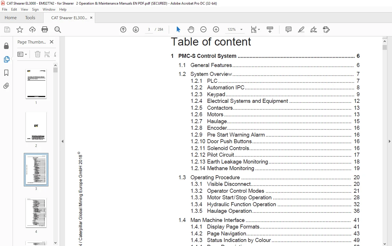
TABLE OF CONTENTS:
CAT Shearer PMC™ Evo-S Control System EL3000 Operating & Maintenance Manual – PDF DOWNLOAD
 Table of content..............................................  3
1 PMC-S Control System.........................................  6
	1.1 General Features.......................................  6
	1.2 System Overview........................................  7
		1.2.1 PLC..............................................  7
		1.2.2 Automation IPC...................................  8
		1.2.3 Keypad...........................................  9
		1.2.4 Electrical Systems and Equipment................. 12
		1.2.5 Contactors....................................... 13
		1.2.6 Motors........................................... 13
		1.2.7 Haulage.......................................... 15
		1.2.8 Encoder.......................................... 16
		1.2.9 Pre Start Warning Alarm.......................... 16
		1.2.10 Door Push Buttons............................... 16
		1.2.11 Solenoid Controls............................... 16
		1.2.12 Pilot Circuit................................... 17
		1.2.13 Earth Leakage Monitoring........................ 18
		1.2.14 Methane Monitoring.............................. 19
	1.3 Operating Procedure.................................... 20
		1.3.1 Visible Disconnect............................... 20
		1.3.2 Operator Control Modes........................... 21
		1.3.3 Motor Start / Stop Operation..................... 28
		1.3.4 Hydraulic Function Operation..................... 32
		1.3.5 Haulage Operation................................ 36
	1.4 Man Machine Interface.................................. 41
		1.4.1 Display Page Formats............................. 41
		1.4.2 Page Navigation.................................. 43
		1.4.3 Status Indication by Colour...................... 49
		1.4.4 Page Descriptions................................ 50
		1.4.5 Device Module Set up............................. 87
		1.4.6 Setting up MAC Table............................. 97
		1.4.7 Software Installation MMC........................100
		1.4.8 Web browser Installation.........................111
		1.4.9 Software Revision Check..........................113
		1.4.10 Parameter Management............................116
2 Control System: Automation...................................124
	2.1 Introduction and Purpose of Auto Steering..............124
		2.1.1 Machine Automation Information...................124
	2.2 Machine Dimensions.....................................124
		2.2.1 Device Positions.................................126
		2.2.2 Machine and Drum Positions.......................127
	2.3 Machine Position Encoders..............................128
		2.3.1 Overview and Commissioning.......................128
		2.3.2 Machine Angle Measurement........................130
		2.3.3 Ranging Arm Potentiometers.......................132
	2.4 General Operation Overview.............................134
		2.4.1 Communication Layout.............................135
		2.4.2 Shearer Radio Transmitter Operation Overview.....135
		2.4.3 Haulage Overview.................................137
		2.4.4 Status Beacons...................................137
		2.4.5 Drum Modes and Automation Methods................138
	2.5 Automation Zones.......................................145
		2.5.1 Face Settings Zones..............................146
		2.5.2 Drum Automation Zones............................146
		2.5.3 Cowl Automation Zones............................148
	2.6 State based Automation.................................148
		2.6.1 State Automation Overview........................149
		2.6.2 Automation State Table Description...............150
		2.6.3 Automation State Quick Guide.....................152
	2.7 Automation Configuration Options.......................155
		2.7.1 Ranging Arm Control Set Up.......................155
		2.7.2 Gain Definitions.................................159
		2.7.3 Limit Definitions................................163
	2.8 Anti-Collision Drum Raise Inhibit......................168
	2.9 LongwallFusion Face Alignment..........................169
	2.10 Enhanced Horizon Control..............................178
	2.11 Extended Functions....................................178
		2.11.1 Dual Tow Arm System.............................178
		2.11.2 Encoder Fail Detect.............................183
		2.11.3 Fibre Offboard Monitoring.......................184
		2.11.4 Hydraulic Filter Monitoring.....................188
		2.11.5 Introduction Gruenewald Oil Level Transducer....190
		2.11.6 Ranging Arm Gear Mesh Enhancement...............194
		2.11.7 Ranging Arm Levelling...........................198
		2.11.8 Shearer Automatic Motor Shutdown................200
		2.11.9 Thermal Inclinometer Enhancement................204
		2.11.10 Water Exclusion Zone Enhancement...............209
	2.12 Remote Control........................................211
		2.12.1 System Overview.................................211
		2.12.2 Display.........................................212
		2.12.3 Operator Modes..................................212
		2.12.4 Visualisation...................................213
		2.12.5 Communications Monitoring.......................215
			2.12.5.1 Link Status Monitoring....................215
			2.12.5.2 Radio Link Loss Monitoring................215
			2.12.5.3 Illegal Transmitter Detection.............215
			2.12.5.4 Signal Strength Monitoring................216
			2.12.5.5 Battery Level Monitoring..................216
			2.12.5.6 Radio Status Monitoring...................216
		2.12.6 Tilt / Drop Detection...........................216
		2.12.7 Handset Display.................................216
		2.12.8 Radio Handset Messaging.........................217
	2.13 Remote Operator Cabin (ROC)...........................219
		2.13.1 Introduction....................................219
		2.13.2 Cabin equipment.................................221
		2.13.3 Shearer Equipment...............................222
		2.13.4 Operating/Handling..............................223
		2.13.5 Faults..........................................225
3 Faults and Alarms............................................227
	3.1 Introduction...........................................227
	3.2 Keypad Overview........................................228
	3.3 Display Pages Overview.................................229
	3.4 Display Pages Menu Overview............................230
	3.5 Faults, Alarm and Event Handling.......................231
		3.5.1 Faults Overview..................................234
		3.5.2 Fault Actions....................................238
		3.5.3 Fault Descriptions...............................241
	3.6 Inactive Functions  /  Transducers.....................242
	3.7 Logged Faults, Alarms and Events.......................244
	3.8 MMC Fault Management...................................246
		3.8.1 Fault List.......................................246
		3.8.2 Fault Description Window.........................247
		3.8.3 Navigation.......................................248
		3.8.4 Flow Chart.......................................248
4 Appendix.....................................................249
	4.1 PMC™ Evo-S Commissioning Menu Pages....................249
	4.2 PMC™ Evo-S Commissioning Automation Pages..............250
	4.3 Faults, Alarms and Events..............................260
		4.3.1 Machine Event Messages...........................261
		4.3.2 Machine Fault Messages...........................262
		4.3.3 Machine Alarm Messages...........................276
		4.3.4 State Automation Faults..........................280
		4.3.5 State Automation Alarms..........................282
Need help? Contact: [email protected]
S.V