CAT Terex SCH2500 SCH3500 SCH4500 HYDRA-TRACE Hydraulic Track Drill System Setup & Maintenance Manual BI116122 – PDF DOWNLOAD
$27.95
CAT Terex SCH2500 SCH3500 SCH4500 HYDRA-TRACE Hydraulic Track Drill System Setup & Maintenance Manual BI116122 – PDF DOWNLOAD
Description
CAT Terex SCH2500 SCH3500 SCH4500 HYDRA-TRACE Hydraulic Track Drill System Setup & Maintenance Manual BI116122 – PDF DOWNLOAD
FILE DETAILS:
CAT Terex SCH2500 SCH3500 SCH4500 HYDRA-TRACE Hydraulic Track Drill System Setup & Maintenance Manual BI116122 – PDF DOWNLOAD
Language : English
Pages : 156
Downloadable : Yes
File Type : PDF
DESCRIPTION:
CAT Terex SCH2500 SCH3500 SCH4500 HYDRA-TRACE Hydraulic Track Drill System Setup & Maintenance Manual BI116122 – PDF DOWNLOAD
HPRI ROTATION END:
- There are several functions of drilling performed by the rotation end. it rotates the shank so that
the drill string is kept tight and re-indexes the bit so new rock Is continually being broken by the
bit. Secondly, through the swivel, the flushing (air or water) Is introduced Into the shank as the
hole can be cleaned of cuttings. There is a third less obvious function and that is to hold the
shank at the appropriate striking position so the hammer can travel the proper distance to deliver
its energy to the end of the shank. - The torque from the rotation motor is delivered through the drive shaft. The pinion end of the
drive shaft is carried by 2 bushings. Torque is delivered through the pinion to the ring gear on the
chuck driver. The chuck has an external and Internal spline. The external spline engages an internal
spline in the chuck driver. The internal spline in the chuck drives the shank.
The entire chuck driver assembly is carried in two large bushings. The chuck driver assembly is made up of four
components:
1. Chuck driver.
2. Chuck.
3. Shank bushing.
4. Thrust collar.
- The swivel assembly has one purpose. That is to direct the flushing medium (or or water) into the
shank. A seal is placed on either side of the flushing slot area of the shank. These seals are held
In place by a pair of bronze seal retainer and snap rings. The seals are supplied with an Internal
back up 0 or quad ring. In many applications better seal life is obtained by removing the Internal
backup rings when new seals are installed. The bronze real retainers may be damaged as a result
of mis-alignment while drilling. They can be cleaned up several times with emery paper or a file
and reused. The swivel seals are a wear item and must be placed periodically. - The internal chuck spline should be inspected for wear each time the shank is removed. Examine
the chuck splines, if high wear Is evident replace the chuck. It is good practice to change the
shank bushing when renewing the chuck. When the chuck is being renewed, it is necessary to
remove the rotation housing cover. At this time Inspect the remainder of the rotation housing Internal
parts. Look for excessive play In the drive shaft bushings.
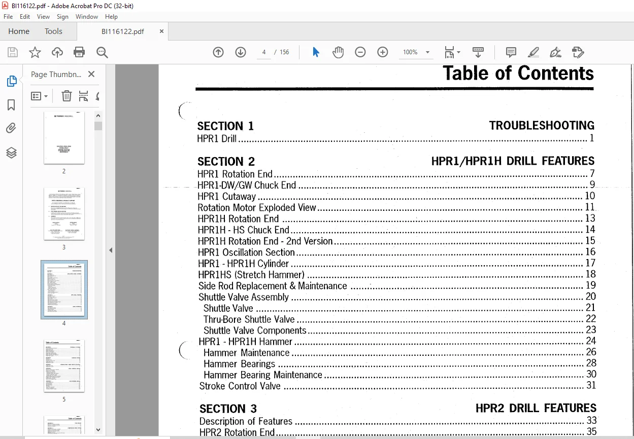
TABLE OF CONTENTS:
CAT Terex SCH2500 SCH3500 SCH4500 HYDRA-TRACE Hydraulic Track Drill System Setup & Maintenance Manual BI116122 – PDF DOWNLOAD
SECTION 1
HPR1 Drill
SECTION 2
TROUBLESHOOTING
HPR1/HPR1H DRILL FEATURES
HPR1 Rotation End 7
HPR1-DW/GW Chuck End 9
HPR1 Cutaway 10
Rotation Motor Exploded View 11.
HPR1H Rotation End 13
HPR1H – HS Chuck End 14
HPR1H Rotation End – 2nd Version 15
HPR1 Oscillation Section 16
HPR1 – HPR1H Cylinder 17
HPR1HS (Stretch Hammer) 18
Side Rod Replacement & Maintenance 19
Shuttle Valve Assembly 20
Shuttle Valve 21
Thru-Bore Shuttle Valve 22
Shuttle Valve Components 23
HPR1 – HPR1H Hammer 24
Hammer Maintenance 26
Hammer Bearings 28
Hammer Bearing Maintenance 30
Stroke Control Valve 31
SECTION 3 HPR2 DRILL FEATURES
Description of Features 33
HPR2 Rotation End 35
HPR2 Oscillation Chamber 36
HPR2 Hammer 37
HPR2 Front Hammer Bearing 38
HPR2 Rear Hammer Bearing 39
HPR2 Shuttle Valve (Thru-Bore Design) 40
HPR2 Shuttle Valve Assembly 41
Hydraulic Oil Specifications 42
Helpful Information (formulas) 44
SECTION 4 BASIC HYDRAULICS
Basic Hydraulic Symbols 47
Typical Directional Valve 48
Hydraulic Symbols 49
Directional Valve Symbols 50
Basic Closed Loop System 51
BI116122
Table of Contents
SECTION 5 HYDRAULIC SYSTEMS
Pressure and Flow Specifications 53
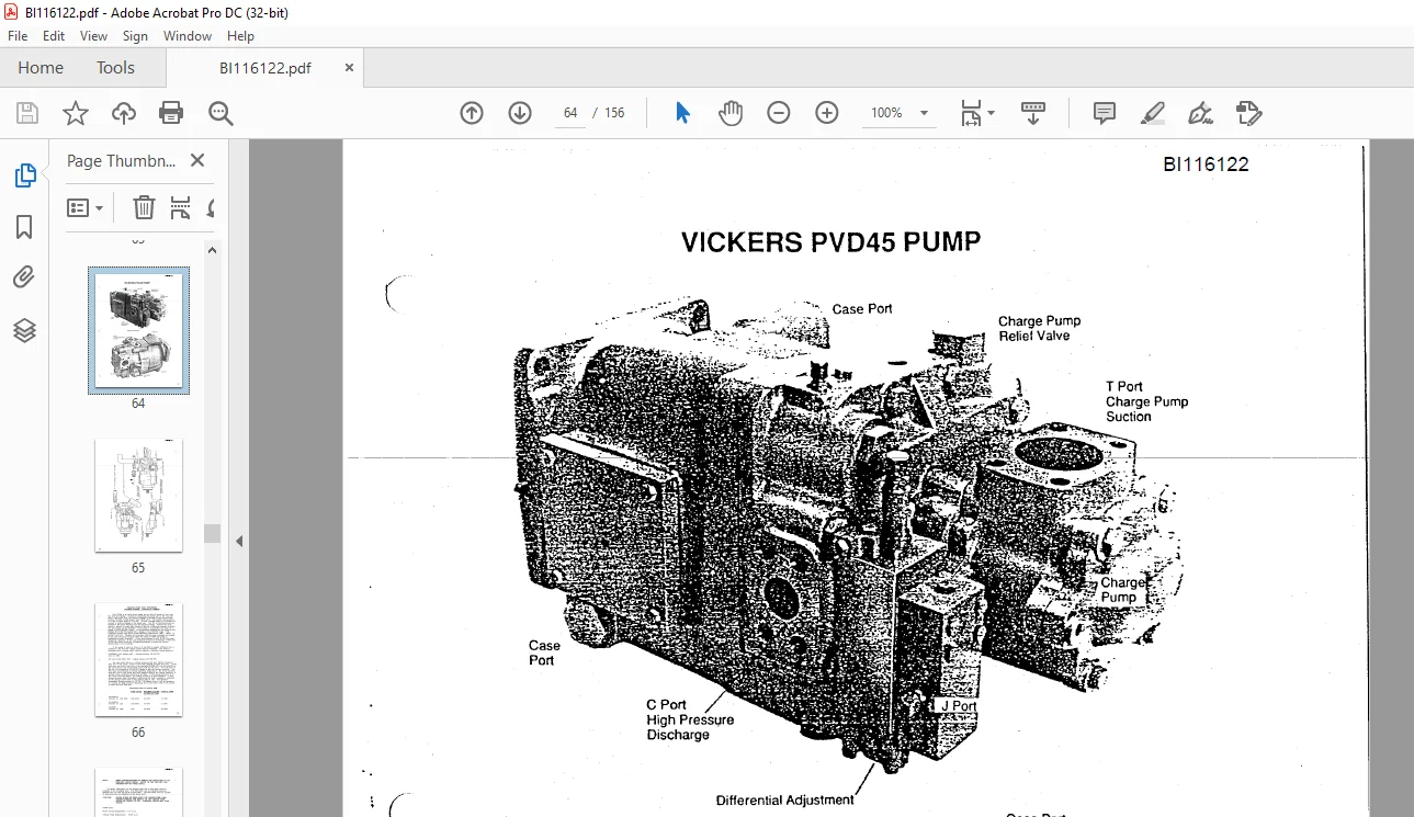
Vickers PVD45 Pump 54
PVD45 Pump Circuit 56
PVD45 Port Identification 57
PVD45Test Procedure … ……. ……… ……. ……… . …………. ……………………….. ….. . …… ….. 59
Piston Pump Troubleshooting 61
PVD45 Pump Main Components 62
PVD45 System Pressure Adjustment 63
PVD45 Pump Control 64
SECTION 6 SCH4500 SYSTEM
Pump Drive 65
Hydraulic Circuit 68
Compressor Pump Circuit 70
System Pump Circuit 72
Adjustment Procedure 74
SECTION 7 VICKERS PVD80 PUMP CIRCUIT (SCH2500)
PVD80 Pump Circuit 76
Adjustment Procedure 77
SECTION 8 DRILL CONTROL CIRCUIT
Drill/Tram Selector Circuit – SCH4500 80
Return Circuit – SCH4500 82
Rotation Circuit – SCH3500 85
Sundstrand Rotation Pump 87
Sundstrand Rotation Pump Controls 89
Pressure Compensator Control 91
Rotation Pump Test Procedure 92
Alternate Rotation Pump Circuit – SCH3500 93
Rotation Circuit – SCH2500 and HT2500 95
Rotation Circuit – SCH4500 97
Vickers PVE19 Rotation Pump 98
SECTION 9 LOAD SENSING CIRCUIT
Load Sensing Control 99
Directional Valves 101
HPI Valve System 103
Manifold Drill Valve 104
Drill Valve 105
Typical HPI Compensator 107
Hammer Compensator 108
Compensator Relief Cartridges 109
SECTION 10 FEED CIRCUIT
Feed Circuit – Hydraulic Drive Motor 111
Feed Circuit – SCH2500 & SCH3500 113
Feed Circuit – SCH4500 114
SECTION 11 COMPRESSOR DRIVE SYSTEM
Compressor Drive System – SCH3500 115
Compressor Circuit with 190 CFM 117
Compressor Circuit with 250 CFM 118
Adjustment Procedure 119
SCH3500 BV1 Compressor Circuit Test Procedure 120
Vented Relief/Unloading Valve 121
Compressor Drive System – SCH2500 122
Compressor Drive System – SCH4500 126
SECTION 12 TRAMMING CIRCUIT
Tramming Circuit – SCH3500 129
Tram System Adjustment Procedure – SCH4500, 3500, 2500 132
Counterbalance Valve & Flow Control Valve 136
Tramming Circuit Test Points 137
Auxiliary Tramming Flow 139
Tramming Circuit – SCH4500 140
SECTION 13 AUXILIARY CIRCUITS
Linear Rod Changer Circuit 143
Rod Wrench Circuit 144
Dust Collector Circuit – SCH3500 & SCH4500 146
Dust Collector Adjustment (Tipton) – SCH3500 & SCH4500 147
Dust Collector Circuit – SCH2500 148
Air Compressor Circuit – SCH3500 149
IMAGES PREVIEW OF THE MANUAL:
Questions? Email us: [email protected]
https://vimeo.com/865038676?share=copy
PLEASE NOTE:
- This is the SAME MANUAL used by the dealerships to diagnose your vehicle
- No waiting for couriers / posts as this is a PDF manual and you can download it within 2 minutes time once you make the payment.
- Your payment is all safe and the delivery of the manual is INSTANT – You will be taken to the DOWNLOAD PAGE.
- So have no hesitations whatsoever and write to us about any queries you may have : heydownloadss @gmail.com
S.V