Cat TH220B & TH330B Telehandler Service Manual – PDF DOWNLOAD
DESCRIPTION:
Cat TH220B & TH330B Telehandler Service Manual – PDF DOWNLOAD
Important Safety Information
Most accidents that involve product operation, maintenance and repair are caused by failure to observe basic safety rules or precautions.
An accident can often be avoided by recognizing potentially hazardous situations before an accident occurs.
A person must be alert to potential hazards. This person should also have the necessary training, skills and tools to perform these functions properly
Improper operation, lubrication, maintenance or repair of this product can be dangerous and could result in injury or death.
Do not operate or perform any lubrication, maintenance or repair on this product, until you have read and understood the operation, lubrication, maintenance and repair information.
Safety precautions and warnings are provided in this manual and on the product. If these hazard warnings are not heeded, bodily injury or death could occur to you or to other persons
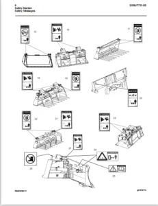
The hazards are identified by the “Safety Alert Symbol” and followed by a “Signal Word” such as “DANGER”, “WARNING” or “CAUTION”. The Safety Alert “WARNING” label is shown below.
WARNING
The meaning of this safety alert symbol is as follows: Attention! Become Alert! Your Safety is Involved.
The message that appears under the warning explains the hazard and can be either written or pictorially presented.
Operations that may cause product damage are identified by “NOTICE” labels on the product and in this publication.
Caterpillar cannot anticipate every possible circumstance that might involve a potential hazard. The warnings in this publication and on the product are, therefore, not all inclusive.
If a tool, procedure, work method or operating technique that is not specifically recommended by Caterpillar is used, you must satisfy yourself that it is safe for you and for others.
You should also ensure that the product will not be damaged or be made unsafe by the operation, lubrication, maintenance or repair procedures that you choose.
The information, specifications, and illustrations in this publication are on the basis of information that was available at the time that the publication was written. The specifications, torques, pressures, measurements, adjustments, illustrations, and other items can change at any time.
These changes can affect the service that is given to the product. Obtain the complete and most current information before you start any job. Caterpillar® dealers have the most current information available.
TABLE OF CONTENTS:
Cat TH220B & TH330B Telehandler Service Manual – PDF DOWNLOAD
31200262_TH220B & TH330B Service Manual....................................................................... 1
31200263_Contents of 31200262............................................................................. 1
TORQUE SPECIFICATIONS..................................................................................... 2
31200268_Torque Specifications........................................................................ 2
Table of Contents................................................................................. 4
Specifications Section............................................................................ 6
General Information........................................................................... 6
Introduction to Torque.................................................................... 6
Torque-Turn............................................................................... 6
Torque Sequence........................................................................... 6
Metric (ISO) Fasteners........................................................................ 7
Metric (ISO) Nuts and Bolts............................................................... 7
Metric (ISO) Taperlock Studs.............................................................. 7
Metric (ISO) Machine Screws............................................................... 7
Hex Button Head Screw and Set Screw....................................................... 7
English (SAE) Fasteners....................................................................... 8
English (SAE) Nuts and Bolts.............................................................. 8
English (SAE) Taperlock Studs............................................................. 8
English (SAE) Machine Screws.............................................................. 8
Hex Button Head Screw and Set Screws...................................................... 9
Ground Engaging Tool (G.E.T.) Fasteners....................................................... 9
Installation of Fittings...................................................................... 10
Installation of Split Flange Couplings.................................................... 10
Installation of Adjustable STOR Fittings.................................................. 11
Straight Thread O-Ring Fittings............................................................... 11
Plugs......................................................................................... 13
Straight Thread O-Ring Plugs (Hex Drive).................................................. 13
Straight Thread O-Ring Plugs (Socket Drive)............................................... 14
Drain Plugs with Straight Thread.......................................................... 14
Straight Thread O-Ring Plugs (Mechanical Joint Tube Assemblies)........................... 14
O-Ring Face Seal Fittings..................................................................... 15
Bulkhead Nuts................................................................................. 15
Flare Fittings................................................................................ 16
37 Degree Flare Fitting................................................................... 16
45 Degree Flare and 45 Degree Inverted Flare Fittings..................................... 16
Air Conditioning Fittings..................................................................... 17
Air Brake Fittings............................................................................ 17
Tapered Pipe Thread Fittings.................................................................. 17
Miscellaneous Fittings........................................................................ 18
Hi Duty Tube Fittings (Shear Sleeve)...................................................... 18
SAE Flareless Fittings.................................................................... 18
Flex Fittings............................................................................. 18
Hose Clamps................................................................................... 18
Worm Drive Band Type Clamps............................................................... 18
Constant Torque Hose Clamps............................................................... 19
ENGINE.................................................................................................... 24
31200269_Engine Disassembly-Assembly.................................................................. 24
Table of Contents................................................................................. 4
Disassembly and Assembly Section.................................................................. 28
Battery - Remove and Install.................................................................. 28
Removal Procedure......................................................................... 28
Installation Procedure.................................................................... 29
Alternator - Remove and Install............................................................... 29
Removal Procedure......................................................................... 29
Installation Procedure.................................................................... 30
Electric Starting Motor -Remove and Install................................................... 30
Removal Procedure......................................................................... 30
Installation Procedure.................................................................... 30
Air Cleaner - Remove and Install.............................................................. 31
Removal Procedure......................................................................... 31
Installation Procedure.................................................................... 31
Muffler - Remove and Install.................................................................. 32
Removal Procedure......................................................................... 32
Installation Procedure.................................................................... 33
Expansion Tank - Remove and Install........................................................... 34
Removal Procedure......................................................................... 34
Radiator - Remove............................................................................. 35
Removal Procedure......................................................................... 35
Radiator - Install............................................................................ 39
Installation Procedure.................................................................... 39
Fan Guard - Remove and Install................................................................ 42
Removal Procedure......................................................................... 42
Installation Procedure.................................................................... 42
Fan - Remove and Install...................................................................... 42
Removal Procedure......................................................................... 42
Installation Procedure.................................................................... 43
Engine Mount - Remove and Install............................................................. 43
Removal Procedure......................................................................... 43
Installation Procedure.................................................................... 45
Refrigerant Compressor - Remove and Install................................................... 47
Removal Procedure......................................................................... 47
Installation Procedure.................................................................... 48
Refrigerant Condenser - Remove and Install.................................................... 48
Removal Procedure......................................................................... 48
Installation Procedure.................................................................... 49
Engine Enclosure - Remove and Install......................................................... 50
Removal Procedure......................................................................... 50
Installation Procedure.................................................................... 51
Engine - Remove............................................................................... 52
Removal Procedure......................................................................... 52
Engine - Install.............................................................................. 58
Installation Procedure.................................................................... 58
POWER TRAIN............................................................................................... 70
31200270_Power Train Test-Adjust...................................................................... 70
Table of Contents................................................................................. 4
Systems Operation Section......................................................................... 74
Graphic Color Codes........................................................................... 74
Introduction.................................................................................. 75
General Information........................................................................... 76
Location of Electrical Components............................................................. 77
Transmission Neutralizer Switch........................................................... 78
Parking Brake Switch...................................................................... 78
Service Brake Pressure Switch............................................................. 78
Transmission Direction Control Lever (Power Shuttle Transmission)......................... 79
Transmission Speed Selector (Powersynchro Transmission)................................... 79
Differential Lock Switch (if Equipped..................................................... 79
Transmission Oil Temperature Sensor....................................................... 79
Torque Converter Output Sensor for the Temperature of the Oil............................. 79
Engine Speed Sensor....................................................................... 79
Torque Converter Output Speed Sensor...................................................... 79
Transmission Intermediate Speed Sensors................................................... 80
Transmission Output Speed Sensor.......................................................... 80
Shift Rail Sensors........................................................................ 80
Electronic Control Module................................................................. 80
Modulating Valve for the Synchronizers.................................................... 80
Solenoid Valves........................................................................... 81
Transmission Neutralizer Override Switch.................................................. 81
Location of Hydraulic Components.............................................................. 81
Transmission Charge Pump.................................................................. 82
Torque Converter.......................................................................... 82
Hydraulic Oil Cooler...................................................................... 82
Electrical Input Components................................................................... 83
Sensors................................................................................... 83
Switches.................................................................................. 85
Transmission Control...................................................................... 86
Electronic Control Module..................................................................... 87
Inputs.................................................................................... 87
Outputs................................................................................... 87
Input/Output.............................................................................. 87
Electrical Output Components.................................................................. 91
Synchronizer Solenoids.................................................................... 92
Directional Solenoids..................................................................... 92
Instrument Cluster........................................................................ 92
Data Link..................................................................................... 93
CAT Data Link............................................................................. 93
CAN Data Link............................................................................. 93
Electrical Schematic.......................................................................... 93
Transmission Charge Pump...................................................................... 95
Modulating Valve (Transmission)............................................................... 95
Solenoid Valves (Transmission)................................................................ 95
Directional Solenoids..................................................................... 95
Speed or Synchronized Solenoids........................................................... 96
Torque Converter.............................................................................. 97
Transmission.................................................................................. 99
Clutch Operation.......................................................................... 102
Operation of the Synchronizers............................................................ 103
Synchronizer for the Third Speed and Fourth Speed......................................... 106
Limits.................................................................................... 108
Cooler (Hydraulic Oil)........................................................................ 109
Transmission Control (Shift Lever)............................................................ 109
Powersynchro Transmission................................................................. 110
Power Shuttle Transmission................................................................ 110
Transmission Power Flow....................................................................... 111
Examples of Power Flow Through the Transmission........................................... 113
Differential Lock Control (If Equipped)....................................................... 115
Front Axle and Rear Axle...................................................................... 117
Final Drives.............................................................................. 117
Hydraulic Schematic (Power Train System)...................................................... 119
Neutral (Power Shuttle Transmission)...................................................... 119
Neutral (Powersynchro Transmission)....................................................... 120
Neutral into First Gear (Start of shift).................................................. 121
Neutral Into First Gear (End of Shift) (FORWARD).......................................... 122
Configuration Parameters...................................................................... 124
Testing and Adjusting Section..................................................................... 126
Transmission Shift Rail - Calibrate........................................................... 126
Machine Preparation....................................................................... 126
Transmission Fill - Calibrate................................................................. 133
Machine Preparation....................................................................... 133
Torque Converter Stall - Test................................................................. 140
Introduction.............................................................................. 140
Required Tools............................................................................ 140
Test Procedure............................................................................ 140
Measurement of the Stall Speed............................................................ 141
Transmission Pressures - Test and Adjust...................................................... 141
Pressure Test Points for the Powersynchro Transmission.................................... 142
Pressure Test Points for the Power Shuttle Transmission................................... 143
Oil Level Check........................................................................... 143
Torque Converter Inlet Pressure........................................................... 143
Regulated Pump Pressure................................................................... 144
Operating Pressures of Clutches and Synchronizers......................................... 145
Differential Pinion Bearing - Adjust.......................................................... 146
Introduction.............................................................................. 146
Required Tools............................................................................ 146
Procedure................................................................................. 147
Differential Backlash and Bearings - Adjust................................................... 152
Front Axle Differential................................................................... 152
Rear Axle Differential.................................................................... 155
Tooth Contact Pattern..................................................................... 156
Axle Housing and Bearing Preload - Adjust..................................................... 158
Introduction.............................................................................. 158
Adjustment Procedure...................................................................... 159
31200271_Power Train Disassembly-Assembly............................................................. 164
Table of Contents................................................................................. 4
Disassembly and Assembly Section.................................................................. 168
Transmission Control (Select Lever) - Remove and Install...................................... 168
Removal Procedure......................................................................... 168
Installation Procedure.................................................................... 170
Drive Shaft (Front) - Remove and Install...................................................... 171
Removal Procedure......................................................................... 171
Installation Procedure.................................................................... 172
Drive Shaft (Rear) - Remove and Install....................................................... 172
Removal Procedure......................................................................... 172
Installation Procedure.................................................................... 173
Transmission and Torque Converter - Remove.................................................... 173
Removal Procedure......................................................................... 173
Transmission - Disassemble.................................................................... 178
Disassembly Procedure..................................................................... 178
Transmission - Assemble....................................................................... 206
Assembly Procedure........................................................................ 206
Transmission and Torque Converter - Install................................................... 234
Installation Procedure.................................................................... 234
Drive and Steering Axle (Front) - Remove...................................................... 238
Removal procedure......................................................................... 238
Drive and Steering Axle (Front) - Install..................................................... 240
Installation Procedure.................................................................... 240
Drive and Steering Axle (Rear) - Remove....................................................... 241
Removal procedure......................................................................... 241
Drive and Steering Axle (Rear) - Install...................................................... 243
Installation Procedure.................................................................... 243
Tie Rod (Steering) - Remove and Install....................................................... 245
Removal Procedure......................................................................... 245
Installation procedure.................................................................... 246
Steering Cylinder - Remove and Install........................................................ 246
Removal Procedure......................................................................... 246
Installation Procedure.................................................................... 248
Final Drive Planetary - Remove................................................................ 249
Removal Procedure......................................................................... 249
Final Drive Planetary Disassemble............................................................. 249
Disassembly Procedure..................................................................... 249
Final Drive Planetary - Assemble.............................................................. 250
Assembly Procedure........................................................................ 250
Final Drive Planetary - Install............................................................... 250
Installation Procedure.................................................................... 250
Axle Housing and Flange Remove................................................................ 250
Removal Procedure......................................................................... 250
Axle Housing and Flange - Disassemble......................................................... 253
Disassembly Procedure..................................................................... 253
Axle Housing and Flange - Assemble............................................................ 255
Assembly Procedure........................................................................ 255
Axle Housing and Flange Install............................................................... 257
Installation Procedure.................................................................... 257
Axle Shaft - Remove and Install............................................................... 260
Removal Procedure......................................................................... 260
Installation Procedure.................................................................... 261
Axle Housing (Service Brakes, Differential and Bevel Gear) (Front) - Remove................... 262
Removal Procedure............................................................................. 262
Axle Housing (Service Brakes, Differential and Bevel Gear) (Front) - Disassemble.............. 263
Disassembly Procedure..................................................................... 263
Axle Housing (Service Brakes, Differential and Bevel Gear) (Front) - Assemble................. 269
Assembly Procedure........................................................................ 269
Axle Housing (Service Brakes, Differential and Bevel Gear) (Front) - Install.................. 278
Installation Procedure.................................................................... 278
Axle Housing (Differential and Bevel Gear) (Rear) - Remove.................................... 279
Removal Procedure......................................................................... 279
Axle Housing (Differential and Bevel Gear) (Rear) - Assemble.................................. 280
Assembly Procedure........................................................................ 280
Axle Housing (Differential and Bevel Gear) (Rear) - Disassemble............................... 285
Disassembly Procedure..................................................................... 285
Axle Housing (Differential and Bevel Gear) (Rear) - Install................................... 289
Installation Procedure.................................................................... 289
Brake Cylinder (Master) Remove and Install.................................................... 289
Removal Procedure......................................................................... 289
Installation Procedure.................................................................... 291
Parking Brake Control -Remove and Install..................................................... 292
Removal Procedure......................................................................... 292
Installation Procedure.................................................................... 293
Parking Brake - Remove........................................................................ 294
Removal Procedure......................................................................... 294
Parking Brake - Disassemble................................................................... 294
Disassembly Procedure..................................................................... 294
Parking Brake - Assemble...................................................................... 296
Assembly Procedure........................................................................ 296
Parking Brake - Install....................................................................... 298
Installation Procedure.................................................................... 298
Tire and Rim - Remove and Install............................................................. 299
Removal Procedure......................................................................... 299
Installation Procedure.................................................................... 300
VEHICLE SYSTEMS........................................................................................... 306
31200275_Hydraulic System Schematic................................................................... 306
31200272_Hydraulic System Test Adjust................................................................. 308
Table of Contents................................................................................. 4
Systems Operation Section......................................................................... 312
Graphic Color Codes........................................................................... 312
Introduction.................................................................................. 313
General Information........................................................................... 314
Main Control Valve Group (Implement)...................................................... 314
Electronic Pilot Valve Group (Implement).................................................. 315
Machine ECM............................................................................... 316
Electronic Joystick....................................................................... 317
Operator Switches......................................................................... 318
Piston Pump (Implement and Steering)...................................................... 318
Hydraulic Oil Tank........................................................................ 318
Hydraulic Oil Filter...................................................................... 318
System Operation.......................................................................... 319
Load Independent Flow Division (LIFD)..................................................... 320
Location of Electrical Components......................................................... 320
Switch (Lockout Control).................................................................. 320
Joystick Control.......................................................................... 320
Sensor (Boom Raise/Lower)................................................................. 321
Sensor For Boom Extend And Boom Retract Or Boom Tilt Forward And Rackback................. 321
Switch (Continuous Auxiliary Flow)........................................................ 321
Switch For Boom Extend and Boom Retract Or Boom Tilt Forward And Rackback................. 321
Switch (Auxiliary Actuator in the + Direction)............................................ 321
Switch (Auxiliary Actuator in the - Direction)............................................ 321
Switch (Auxiliary Services 1 or 2)........................................................ 321
Switch (Quick Coupler).................................................................... 322
Switch (Frame Level)...................................................................... 322
Switch (Fully Lowered Boom)............................................................... 322
Switch (Critical Angle)................................................................... 323
Switch (Fully Retracted Boom)............................................................. 323
Switch (Reversing Fan (If Equipped))...................................................... 323
Machine (ECM)............................................................................. 323
Main Control Valve (Implement)............................................................ 324
Solenoids (Frame Level)................................................................... 324
Solenoid (Diverter Valve)................................................................. 324
Relay (Frame Level)....................................................................... 325
Relays (Diverter Valve)................................................................... 325
Relays (Quick Coupler).................................................................... 325
Location of Hydraulic Components.............................................................. 326
Hydraulic Tank............................................................................ 326
Piston Pump (Implement and Steering)...................................................... 326
Compensator Valve......................................................................... 327
Main Control Valve Group (Implement)...................................................... 327
Inlet Manifold............................................................................ 327
Outlet Manifold........................................................................... 328
Trailer and Towing Hitch Hydraulic System (Option)........................................ 328
Boom Cylinder............................................................................. 329
Load Control Valve (Boom Cylinder Lock)................................................... 330
Telescoping Cylinder...................................................................... 330
Load Control Valve (Telescoping Cylinder Lock)............................................ 330
Tilt Cylinder............................................................................. 330
Lock for Load Control Valve (Tilt Cylinder)............................................... 331
Compensating Cylinder..................................................................... 331
Load Control Valve (Compensating Cylinder Lock)........................................... 331
Frame Leveling Cylinder................................................................... 331
Lock Valve (Frame Leveling Cylinder)...................................................... 332
Diverter Valve............................................................................ 332
Quick Coupler Cylinder.................................................................... 332
Electrical Input Components................................................................... 333
Switches.................................................................................. 334
Joystick Control.......................................................................... 334
Auxiliary Switches........................................................................ 334
Thumb Slider.............................................................................. 334
Boom Critical Angle Switch................................................................ 334
Frame Leveling Switch..................................................................... 334
Boom Retracted Switch..................................................................... 334
Quick Coupler Switch...................................................................... 335
Continuous Flow Switch.................................................................... 335
Implement Lockout Switch.................................................................. 335
Boom Lowered Switch....................................................................... 335
Electronic Control Module..................................................................... 336
Inputs.................................................................................... 336
Outputs................................................................................... 336
Data Links................................................................................ 336
Input/Output.............................................................................. 336
Electrical Output Components.................................................................. 338
Relays.................................................................................... 339
Solenoids................................................................................. 339
Electrical Function Requirements.............................................................. 340
Transmission Neutralizer.................................................................. 340
Solenoid Outputs.......................................................................... 340
System Voltage............................................................................ 340
Shuttle Shift for the Power Shuttle Transmission.......................................... 340
Shift Lever (Cat Data Link) for Powersynchro Transmission................................. 340
Rear Axle Lock (if equipped).............................................................. 340
Machine Security System................................................................... 340
Parking Brake............................................................................. 340
Service Brake Pressure Switch for the Transmission Neutralizer............................ 340
More Electrical Function Requirements..................................................... 340
Steering.................................................................................. 341
The Neutral Start Is Disabled............................................................. 341
Stabilizer Raise/Lower (if equipped) is Disabled.......................................... 341
Boom Raise/Lower Is Disabled.............................................................. 342
The Boom Extend/Retract Is Disabled....................................................... 342
Disable The Rackback And Dump............................................................. 342
The Frame Level (if equipped) is Disabled................................................. 342
Disable the Quick Coupler................................................................. 343
Miscellaneous............................................................................. 343
Electrical Schematic.......................................................................... 344
Programmable Hydraulic System (PHS)....................................................... 345
Piston Pump (Implement and Steering).......................................................... 346
Piston Pump............................................................................... 346
Compensator Valve......................................................................... 347
Low Pressure Standby...................................................................... 348
Upstroke.................................................................................. 349
Constant Flow............................................................................. 350
Destroke.................................................................................. 351
High Pressure Stall....................................................................... 353
Main Control Valve (Implement)............................................................ 354
Manifold Valve (Inlet).................................................................... 356
Check and Relief Valves....................................................................... 358
Manifold Valve (Outlet)....................................................................... 358
Pilot Hydraulic System........................................................................ 360
Telescoping System............................................................................ 362
Valve for the Telescoping Cylinder in the HOLD Position................................... 362
Valve for the Telescoping Cylinder in the EXTEND Position................................. 364
Valve for the Telescoping Cylinder in the RETRACT Position................................ 366
Hydraulic Fan System.......................................................................... 367
Reversing Fan (If Equipped)............................................................... 367
Auxiliary Hydraulic System.................................................................... 369
Auxiliary Control (Combined Circuit)...................................................... 370
Auxiliary Circuit 1....................................................................... 372
Auxiliary Circuit 2....................................................................... 373
Continuous Flow (Auxiliary Hydraulics).................................................... 374
Quick Coupler............................................................................. 374
Quick Coupler Circuit DISENGAGED.......................................................... 375
Quick Coupler Pins ENGAGED................................................................ 376
Relief Valves and Makeup Valves........................................................... 376
Compensating System........................................................................... 377
Trailer and Towing Hitch Hydraulic System..................................................... 381
Introduction.............................................................................. 381
Towing Hitch Cylinder LOWER............................................................... 383
Towing Hitch Cylinder RAISE............................................................... 385
Trailer DUMP.............................................................................. 388
Trailer LOWER............................................................................. 390
Service Brakes ENGAGED.................................................................... 393
Hydraulic System Schematic.................................................................... 394
Configuration Parameters...................................................................... 397
Testing and Adjusting Section..................................................................... 398
Testing and Adjusting......................................................................... 398
Joystick Control - Calibrate.............................................................. 398
Main Control Valve (Implement) - Calibrate.................................................... 418
Programmable Hydraulic System (PHS) Valve Calibrations.................................... 418
Manual Adjustment After Calibrating The Valves............................................ 427
Hydraulic System Pressure - Release........................................................... 427
Relieving Pressure in the Hydraulic System................................................ 428
Location of the Load Control Valve (Lock)................................................. 428
Relieving Pressure from the Load Control Valves (Lock).................................... 429
Hydraulic System Pressures - Test and Adjust.................................................. 432
Test and Adjustment Procedures............................................................ 432
Pilot Pressure (Pressure Reducing Valve) - Test and Adjust.................................... 432
Pilot Pressure Test....................................................................... 432
Pressure Reducing Valve Adjustment........................................................ 434
Relief Valve (Implement) - Test and Adjust.................................................... 434
Auxiliary Pressure Test (Port A and Port B)............................................... 434
Auxiliary Relief Valve Adjustments........................................................ 436
Hydraulic Oil Contamination - Test............................................................ 436
Hydraulic Oil Contamination............................................................... 436
Flushing the Sampling Valve............................................................... 436
Obtaining the Sample...................................................................... 437
General Information Table..................................................................... 438
31200273_Steering System Test-Adjust.................................................................. 444
Table of Contents................................................................................. 4
Systems Operation Section......................................................................... 448
Graphic Color Codes........................................................................... 448
General Information........................................................................... 449
Steering Arrangement...................................................................... 449
Introduction.................................................................................. 451
Location of Electrical Components............................................................. 452
Selector Switch for the Steering Mode..................................................... 452
Position Sensors.......................................................................... 452
Electronic Control Module................................................................. 453
Solenoid for Crab Steer................................................................... 453
Solenoid for Circle Steer................................................................. 453
Relay (Crab Steer)........................................................................ 453
Relay (Circle Steer)...................................................................... 454
Location of Hydraulic Components.............................................................. 454
Steering Wheel............................................................................ 454
Metering Pump............................................................................. 455
Piston Pump............................................................................... 455
Line for the Signal Limiter Valve for the Steering........................................ 455
Priority Valve............................................................................ 455
Control Valve (Steering).................................................................. 456
Steering Cylinders........................................................................ 334
Hydraulic Tank............................................................................ 456
Hydraulic Tank Breather................................................................... 456
Hydraulic Oil Level Indicator............................................................. 457
Hydraulic Oil Drain Plugs................................................................. 457
Electrical Input Components................................................................... 457
Steering Mode Switch...................................................................... 457
Position Sensor........................................................................... 458
Electronic Control Module..................................................................... 458
Electrical Output Components.................................................................. 459
Relays.................................................................................... 459
Instrument Cluster........................................................................ 459
Data Link..................................................................................... 459
CAT Data Link............................................................................. 459
CAN Data Link............................................................................. 460
Electrical Schematic.......................................................................... 460
Inlet Manifold................................................................................ 460
Steering Priority Valve................................................................... 461
Screens (75 and 100 Micron)............................................................... 461
Flow Control Valve (Dump valve for the load sensing oil).................................. 461
Relief Valve (Load sensing oil)........................................................... 461
Check Valve............................................................................... 461
Steering Not Activated.................................................................... 462
Steering Activated........................................................................ 463
Steering System............................................................................... 464
Steering Control System................................................................... 464
Steering in Neutral....................................................................... 465
Right Turn in Two-Wheel Steer Mode........................................................ 467
Left Turn in Circle Steer Mode............................................................ 469
Left Turn in Crab Steer Mode.............................................................. 471
Hydraulic Schematic (Steering System)......................................................... 473
Piston Pump (Implement and Steering).......................................................... 474
Piston Pump............................................................................... 474
Compensator Valve......................................................................... 475
Low Pressure Standby...................................................................... 476
Upstroke.................................................................................. 477
Constant Flow............................................................................. 478
Destroke.................................................................................. 479
High Pressure Stall....................................................................... 481
Solenoid Valve (Steering Mode Selector)....................................................... 482
Solenoid Valve............................................................................ 482
Metering Pump (Steering)...................................................................... 482
Hold...................................................................................... 484
Right Turn................................................................................ 485
Position Sensor (Steering).................................................................... 487
Configuration Parameters...................................................................... 488
Testing and Adjusting Section..................................................................... 490
Hydraulic Oil Contamination - Test............................................................ 490
Hydraulic Oil Contamination............................................................... 490
Flushing the Sampling Valve............................................................... 490
Obtaining the Sample...................................................................... 490
Pump Flow - Test.............................................................................. 491
Pump Flow................................................................................. 491
Test On The Machine....................................................................... 491
Test On The Bench......................................................................... 492
Steering System Pressures - Test and Adjust................................................... 492
Steering System Pressure Tests and Adjustments............................................ 492
Steering Pressure Test.................................................................... 493
Steering Pressure Adjustment.............................................................. 493
Margin Pressure Test...................................................................... 494
Margin Pressure Adjustment................................................................ 495
Test for the Relief Valve (Load Sensing Oil).............................................. 495
Adjustment of the Relief Valve (Load Sensing Oil)......................................... 496
Test for Pressure Compensator............................................................. 496
Pressure Compensator Adjustment........................................................... 497
Low Pressure Standby Test................................................................. 497
Low Pressure Standby Adjustment........................................................... 498
Steering System - Purge....................................................................... 499
Purging the Steering System............................................................... 499
Solenoid Valve (Steering Mode Selector) - Test................................................ 499
The Solenoid's for the Steering Modes..................................................... 499
Position Sensor (Steering) - Adjust........................................................... 500
Position Sensor........................................................................... 500
Wheel Alignment - Check and Adjust............................................................ 502
Checking the Wheel Alignment With Wheels In Place......................................... 503
Adjusting the Wheel Alignment............................................................. 503
Adjusting the Steering Angle.............................................................. 504
General Information Table..................................................................... 505
31200274_Braking System Test-Adjust................................................................... 510
Table of Contents................................................................................. 4
Systems Operation Section......................................................................... 168
Graphic Color Codes........................................................................... 514
Introduction.................................................................................. 515
General Information........................................................................... 516
Brake Packs............................................................................... 516
Brake Pedal............................................................................... 516
Brake Cylinder............................................................................ 516
Service Brake Pressure Switch............................................................. 517
Parking Brake Lever....................................................................... 517
Location of Electrical Components............................................................. 517
Parking Brake Switch...................................................................... 517
Service Brake Pressure Switch............................................................. 517
Stoplight Switch.......................................................................... 517
Location of Components (Braking).............................................................. 518
Parking Brake Lever....................................................................... 518
Parking Brake Actuator.................................................................... 518
Service Brake Pedal....................................................................... 518
Brake Cylinder............................................................................ 519
Service Brake Discs....................................................................... 519
Service Brake................................................................................. 519
Service Brake............................................................................. 519
The Service Brake System with the Brakes Disengaged....................................... 521
The Service Brake System with the Brakes Engaged.......................................... 522
Parking Brake................................................................................. 523
Engaging the Parking Brake................................................................ 523
Disengaging the Parking Brake............................................................. 524
Brake Cylinder (Master)....................................................................... 525
Brake Cylinder with the Brakes Disengaged................................................. 526
Brake Cylinder with the Brakes Engaged.................................................... 528
Hydraulic Schematic (Braking System).......................................................... 530
Configuration Parameters...................................................................... 531
Electrical Function Requirements.............................................................. 532
Transmission Neutralizer.................................................................. 532
System Voltage............................................................................ 532
Shuttle Shift for the Power Shuttle Transmission.......................................... 532
Shift Lever (Cat Data Link) for Powersynchro Transmission................................. 532
Rear Axle Lock (if equipped).............................................................. 448
Machine Security System................................................................... 448
Parking Brake............................................................................. 532
Service Brake Pressure Switch for the Transmission Neutralizer............................ 533
More Electrical Function Requirements......................................................... 533
Steering.................................................................................. 533
The Neutral Start Is Disabled............................................................. 449
Stabilizer Raise/Lower (if equipped) is Disabled.......................................... 534
Boom Raise/Lower Is Disabled.............................................................. 534
The Boom Extend/Retract Is Disabled....................................................... 534
Disable The Rackback And Dump............................................................. 534
The Frame Level (if equipped) is Disabled................................................. 535
Disable the Quick Coupler................................................................. 535
Miscellaneous............................................................................. 535
Testing and Adjusting Section..................................................................... 536
Testing and Adjusting Service Brake - Test.................................................... 536
Holding Ability Test for the Service Brakes............................................... 536
Stopping Performance Test for the Service Brakes.......................................... 398
Service Brake Control - Check and Adjust...................................................... 536
Adjusting the Brake Pedal Linkage......................................................... 536
Service Brake Discs - Check................................................................... 538
Checking the Wear on the Service Brake Discs.............................................. 538
Procedure for Checking the Wear........................................................... 538
Service Brake Air - Purge..................................................................... 539
Purging Air from the Braking System....................................................... 539
Parking Brake - Test.......................................................................... 540
Holding Ability Test for the Parking Brake................................................ 540
Parking Brake Control - Check and Adjust...................................................... 541
Adjusting the Parking Brake Control Cable................................................. 541
31200276_Machine Components Specifications............................................................ 548
Table of Contents................................................................................. 4
Specifications Section............................................................................ 552
Hydraulic Tank................................................................................ 552
Piston Pump (Implement and Steering).......................................................... 553
Solenoid Valve (Pilot Selector)............................................................... 554
Frame......................................................................................... 557
Boom.......................................................................................... 558
Boom Cylinder................................................................................. 173
Boom Cylinder................................................................................. 560
Boom Cylinder................................................................................. 561
Load Control Valve (Boom Cylinder) (Lock)..................................................... 533
Compensating Cylinder......................................................................... 563
Compensating Cylinder......................................................................... 564
Telescoping Cylinder.......................................................................... 565
Telescoping Cylinder.......................................................................... 566
Load Control Valve (Telescoping Cylinder) (Lock).............................................. 567
Tilt Cylinder................................................................................. 568
Tilt Cylinder................................................................................. 569
Load Control Valve (Tilt Cylinder) (Lock)..................................................... 570
Diverter Valve................................................................................ 570
Diverter Valve................................................................................ 571
Towing Hitch.................................................................................. 572
Towing Hitch.................................................................................. 572
Towing Hitch.................................................................................. 459
Towing Hitch.................................................................................. 572
Towing Hitch.................................................................................. 460
Towing Hitch.................................................................................. 460
Piston Pump (Hydraulic Fan)................................................................... 574
Piston Pump Gp............................................................................ 574
Relief Valve.............................................................................. 574
Elbow..................................................................................... 574
Solenoid Valve Gp......................................................................... 574
Fan Drive Mounting Group...................................................................... 575
Metering Pump (Steering)...................................................................... 576
Solenoid Valve (Steering Mode Selector)....................................................... 576
Position Sensor (Steering).................................................................... 576
Flexible Coupling Drive....................................................................... 340
Transmission.................................................................................. 578
Transmission.................................................................................. 580
Position Sensor (Transmission)................................................................ 581
Oil Filter.................................................................................... 582
Hydraulic Oil Cooler.......................................................................... 584
Drive Shaft................................................................................... 585
Drive Shaft................................................................................... 585
Drive and Steering Axle (Front)............................................................... 586
168-7440 Drive and Steering Axle Gp....................................................... 586
271 -6424 Drive and Steering Axle Gp...................................................... 587
Drive and Steering Axle (Rear)................................................................ 589
168-7441 Drive and Steering Axle Gp....................................................... 589
Differential and Bevel Gear Group............................................................. 590
Axle Housing and Flange Group................................................................. 517
Axle Housing and Flange Group................................................................. 369
Final Drive Planetary Group................................................................... 592
Axle Housing Group (Differential and Brake Cylinder).......................................... 593
238-5225 Axle Housing Gp with a Locking Differential...................................... 593
231 -0737 Axle Housing Gp without a Locking Differential.................................. 594
Brake Cylinder (Master)....................................................................... 596
Parking Brake Control......................................................................... 597
Parking Brake................................................................................. 598
Fender........................................................................................ 598
Wheel (Tire and Rim).......................................................................... 599
Fuel Tank (Auxiliary)......................................................................... 600
Fuel Tank..................................................................................... 601
Engine Enclosure.............................................................................. 602
Engine and Transmission Mounting.............................................................. 604
Air Cleaner................................................................................... 605
Engine Oil Drain.............................................................................. 607
Muffler....................................................................................... 608
Suction Fan................................................................................... 609
Battery....................................................................................... 610
Coolant Lines Group........................................................................... 611
Coolant Recovery Group........................................................................ 612
Cab........................................................................................... 613
Latch Adjustment.......................................................................... 614
Cab Mounting.................................................................................. 615
Cab Door...................................................................................... 616
Access Door................................................................................... 618
Joystick Control.............................................................................. 619
Steering Wheel and Column..................................................................... 620
Window Wiper and Wiper Motor.................................................................. 621
Window Washer Tank............................................................................ 622
Rear View Mirror.............................................................................. 623
Work Tool Linkage............................................................................. 623
Carriage Cylinder (Rotate).................................................................... 624
Carriage Cylinder (Sideshift)................................................................. 624
Hydraulic Cylinder (Multipurpose Bucket)...................................................... 625
Grapple Cylinder.............................................................................. 626
31200277_Machine Systems Disassembly-Assembly......................................................... 632
Table of Contents................................................................................. 4
Disassembly and Assembly Section.................................................................. 636
Hydraulic System Pressure - Release........................................................... 168
Release Procedure......................................................................... 636
Bottom Guard - Remove and Install............................................................. 636
Removal Procedure......................................................................... 636
Installation Procedure.................................................................... 637
Hydraulic Tank - Remove....................................................................... 637
Removal Procedure......................................................................... 637
Hydraulic Tank - Install...................................................................... 639
Installation Procedure.................................................................... 639
Piston Pump (Implement and Steering) - Remove................................................. 640
Removal Procedure......................................................................... 640
Piston Pump (Implement and Steering) - Disassemble............................................ 641
Disassembly Procedure..................................................................... 641
Piston Pump (Implement and Steering) - Assemble............................................... 646
Assembly Procedure........................................................................ 531
Piston Pump (Implement and Steering) - Install................................................ 651
Installation Procedure.................................................................... 651
Main Control Valve (Implement) - Remove....................................................... 652
Removal Procedure......................................................................... 652
Electronic Pilot Valve - Remove and Install................................................... 655
Removal Procedure......................................................................... 655
Installation Procedure.................................................................... 656
Bank Valve (Implement) - Disassemble.......................................................... 657
Disassembly Procedure..................................................................... 657
Bank Valve (Implement) - Assemble............................................................. 345
Assembly Procedure........................................................................ 664
Main Control Valve (Implement) - Install...................................................... 670
Installation Procedure.................................................................... 670
Tilt Cylinder - Remove and Install............................................................ 672
Removal Procedure......................................................................... 672
Installation Procedure.................................................................... 674
Control Valve (Compensating Cylinder) - Remove and Install.................................... 675
Removal Procedure......................................................................... 675
Installation Procedure.................................................................... 676
Compensating Cylinder Remove and Install...................................................... 677
Removal Procedure......................................................................... 677
Installation Procedure.................................................................... 679
Load Control Valve (Telescoping Cylinder) Remove and Install.................................. 681
Removal Procedure......................................................................... 681
Installation Procedure.................................................................... 683
Telescoping Cylinder - Remove and Install..................................................... 685
Removal Procedure......................................................................... 685
Installation Procedure.................................................................... 689
Diverter Valve (Boom Head) - Remove and Install............................................... 693
Removal Procedure......................................................................... 693
Installation Procedure.................................................................... 694
Load Control Valve (Boom Cylinder) - Remove and Install....................................... 30
Removal Procedure......................................................................... 695
Installation Procedure.................................................................... 696
Boom Cylinder - Remove and Install............................................................ 698
Removal Procedure......................................................................... 698
Installation Procedure.................................................................... 701
Coupler Cylinder - Remove and Install......................................................... 703
Removal Procedure......................................................................... 703
Installation Procedure.................................................................... 705
Quick Coupler (Hydraulic) - Remove and Install................................................ 707
Removal Procedure......................................................................... 707
Installation Procedure.................................................................... 709
Work Tool Linkage - Remove and Install........................................................ 710
Removal Procedure......................................................................... 710
Installation Procedure.................................................................... 711
Boom - Remove................................................................................. 712
Removal Procedure......................................................................... 712
Boom - Disassemble............................................................................ 716
Disassembly Procedure..................................................................... 716
Boom -Assemble................................................................................ 721
Assembly Procedure........................................................................ 721
Boom - Install................................................................................ 725
Installation Procedure.................................................................... 725
Hydraulic Oil Cooler (Transmission and Hydraulic System) - Remove and Install................. 728
Removal Procedure......................................................................... 728
Installation Procedure.................................................................... 729
Transmission Oil Cooler................................................................... 730
Hitch Cylinder - Remove and Install........................................................... 730
Removal Procedure......................................................................... 730
Installation Procedure.................................................................... 731
Towing Hitch (Hydraulic) - Remove and Install................................................. 732
Removal Procedure......................................................................... 732
Installation Procedure.................................................................... 733
Control Valve (Trailer and Towing Hitch) - Remove............................................. 734
Removal Procedure......................................................................... 734
Control Valve (Trailer and Towing Hitch) - Disassemble........................................ 735
Disassembly Procedure..................................................................... 735
Control Valve (Trailer and Towing Hitch) - Assemble........................................... 738
Assembly Procedure........................................................................ 738
Control Valve (Trailer and Towing Hitch) - Install............................................ 741
Installation Procedure.................................................................... 741
Fuel Tank - Remove............................................................................ 742
Removal Procedure......................................................................... 742
Fuel Tank - Install........................................................................... 743
Installation Procedure.................................................................... 743
Steering Wheel - Remove and Install........................................................... 745
Removal Procedure......................................................................... 745
Installation Procedure.................................................................... 746
Steering Column - Remove...................................................................... 746
Removal Procedure......................................................................... 746
Steering Column - Install..................................................................... 749
Installation Procedure.................................................................... 749
Solenoid Valve (Steering Mode Selector) - Remove and Install.................................. 752
Removal Procedure......................................................................... 752
Installation Procedure.................................................................... 753
Metering Pump (Steering) - Remove............................................................. 754
Removal Procedure......................................................................... 754
Metering Pump (Steering) - Install............................................................ 757
Installation Procedure.................................................................... 757
Window Wiper and Wiper Motor (Front) - Remove and Install..................................... 759
Removal Procedure......................................................................... 759
Installation Procedure.................................................................... 760
Window Wiper and Wiper Motor (Rear) - Remove and Install...................................... 761
Removal Procedure......................................................................... 761
Installation Procedure.................................................................... 762
Window Wiper and Wiper Motor (Roof) - Remove and Install...................................... 764
Removal Procedure......................................................................... 764
Installation procedure.................................................................... 765
Joystick Control - Remove and Install......................................................... 766
Removal Procedure......................................................................... 766
Installation Procedure.................................................................... 767
Seat - Remove and Install..................................................................... 767
Removal Procedure......................................................................... 767
Installation Procedure.................................................................... 768
Cab Heater - Remove........................................................................... 769
Removal Procedure......................................................................... 769
Cab Heater - Install.......................................................................... 771
Installation Procedure.................................................................... 771
Heater Core - Remove and Install.............................................................. 774
Removal Procedure......................................................................... 774
Installation Procedure.................................................................... 774
Air Conditioner - Remove...................................................................... 775
Removal Procedure......................................................................... 775
Air Conditioner - Install..................................................................... 780
Installation Procedure.................................................................... 780
Evaporator Coil - Remove and Install.......................................................... 786
Removal Procedure......................................................................... 786
Installation procedure.................................................................... 786
Blower Motor (Air Conditioner and Heater) - Remove and Install................................ 787
Removal Procedure......................................................................... 787
Installation procedure.................................................................... 790
Cab - Remove.................................................................................. 793
Removal Procedure......................................................................... 793
Cab - Install................................................................................. 799
Installation Procedure.................................................................... 799
Fender - Remove and Install................................................................... 804
Removal Procedure......................................................................... 804
Installation Procedure.................................................................... 804
ELECTRICAL SYSTEMS........................................................................................ 810
31200278_Electrical System Schematic.................................................................. 810
31200279_Electronic Control System, Hydrostatic Transmission Troubleshooting Test-Adjust.............. 814
Table of Contents................................................................................. 816
Introduction...................................................................................... 820
General Information........................................................................... 820
Service Tools................................................................................. 820
Connector Locations........................................................................... 821
Connector Contact Numbers................................................................. 821
Diagnostic Capabilities....................................................................... 822
Monitoring System/Instrument Cluster...................................................... 822
The Caterpillar Electronic Technician (ET)................................................ 823
Logged Event Codes........................................................................ 824
Status Groups For The Electronic Technician............................................... 825
Machine Preparation for Troubleshooting....................................................... 825
General Troubleshooting Information........................................................... 826
Visual Inspection............................................................................. 826
Operational Checks............................................................................ 826
Operational Checks (Braking System)....................................................... 826
Operational Checks (Steering System)...................................................... 827
Operational Checks (Power Train).......................................................... 827
Operational Checks (Hydraulic System)..................................................... 827
Event Code List............................................................................... 829
Warning Levels............................................................................ 829
Indications and System Response........................................................... 829
Troubleshooting........................................................................... 830
Telehandler Event Code List............................................................... 830
Symptom Procedures................................................................................ 832
Steering System............................................................................... 832
Troubleshooting The Steering System....................................................... 832
Brake System.................................................................................. 833
Troubleshooting The Brake System.......................................................... 833
Troubleshooting The Parking Brake......................................................... 834
Transmission.................................................................................. 834
Troubleshooting The Transmission System................................................... 834
Hydraulic System.............................................................................. 836
Troubleshooting The Hydraulic System...................................................... 836
Torque Converter.............................................................................. 838
Troubleshooting The Torque Converter...................................................... 838
Differential and Final Drive.................................................................. 839
The Differential And The Final Drive Troubleshooting...................................... 839
Diagnostic Code Procedures........................................................................ 842
Diagnostic Code List.......................................................................... 842
Module Identifier (MID)................................................................... 842
Component Identifier (CID)................................................................ 842
Failure Mode Identifier (FMI)............................................................. 844
Using the Operator Monitor to Determine Diagnostic Codes...................................... 846
Using Caterpillar Electronic Technician to Determine Diagnostic Codes......................... 846
Active Diagnostic Codes................................................................... 847
Logged Diagnostic Codes................................................................... 848
MID 039 - CID 0041 - FMI 03................................................................... 849
MID 039 - CID 0041 - FMI 04................................................................... 850
MID 039 - CID 0070 - FMI 03................................................................... 851
MID 039 - CID 0070 - FMI 04................................................................... 853
MID 039 - CID 0096 - FMI 03................................................................... 854
MID 039 - CID 0096 - FMI 04................................................................... 855
MID 039 - CID0 110 - FMI 03................................................................... 856
MID 039 - CID 0110 - FMI 04................................................................... 857
MID 039 - CID 0177 - FMI 03................................................................... 858
MID 039 - CID 0177 - FMI 04................................................................... 860
MID 039 - CID 0191 - FMI 02................................................................... 860
MID 039 - CID 0246 - FMI 12................................................................... 862
MID 039 - CID 0262 - FMI 03................................................................... 863
MID 039 - CID 0262 - FMI 04................................................................... 864
MID 039 - CID 0271 - FMI 03................................................................... 865
MID 039 - CID 0271 - FMI 04................................................................... 866
MID 039 - CID 0271 - FMI 05................................................................... 867
MID 039 - CID 0368 - FMI 03................................................................... 869
MID 039 - CID 0368 - FMI 04................................................................... 870
MID 039 - CID 0444 - FMI 03................................................................... 871
MID 039 - CID 0444 - FMI 04................................................................... 872
MID 039 - CID 0444 - FMI 05................................................................... 873
MID 039 - CID 0489 - FMI 02................................................................... 875
MID 039 - CID 0489 - FMI 04................................................................... 877
MID 039 - CID 0490 - FMI 02................................................................... 879
MID 039 - CID 0590 - FMI 02................................................................... 882
MID 039 - CID 0590 - FMI 09................................................................... 884
MID 039 - CID 0590 - FMI 12................................................................... 886
MID 039 - CID 0629 - FMI 04................................................................... 888
MID 039 - CID 0668 - FMI 02................................................................... 889
MID 039 - CID 0668 - FMI 09................................................................... 891
MID 039 - CID 0668 - FMI 12................................................................... 893
MID 039 - CID 0672 - FMI 02................................................................... 895
MID 039 - CID 0702 - FMI 02................................................................... 896
MID 039 - CID 0750 - FMI 02................................................................... 899
MID 039 - CID 0811 - FMI 09................................................................... 900
MID 039 - CID 0817 - FMI 04................................................................... 902
MID 039 - CID 0826 - FMI 03................................................................... 903
MID 039 - CID 0882 - FMI 05................................................................... 905
MID 039 - CID 0882 - FMI 06................................................................... 906
MID 039 - CID 1127 - FMI 00................................................................... 907
MID 039 - CID 1127 - FMI 01................................................................... 910
MID 039 - CID 1127 - FMI 02................................................................... 913
MID 039 - CID 1127 - FMI 08................................................................... 915
MID 039 - CID 1128 - FMI 00................................................................... 918
MID 039 - CID 1128 - FMI 01................................................................... 921
MID 039 - CID 1128 - FMI 02................................................................... 924
MID 039 - CID 1128 - FMI 08................................................................... 927
MID 039 - CID 1138 - FMI 05................................................................... 930
MID 039 - CID 1138 - FMI 06................................................................... 932
MID 039 - CID 1187 - FMI 04................................................................... 933
MID 039 - CID 1189 - FMI 00................................................................... 934
MID 039 - CID 1189 - FMI 01................................................................... 937
MID 039 - CID 1189 - FMI 02................................................................... 939
MID 039 - CID 1189 - FMI 08................................................................... 942
MID 039 - CID 1193 - FMI 05................................................................... 945
MID 039 - CID 1193 - FMI 06................................................................... 947
MID 039 - CID 1251 - FMI 08................................................................... 948
MID 039 - CID 1326 - FMI 02................................................................... 949
MID 039 - CID 1401 - FMI 03................................................................... 950
MID 039 - CID 1401 - FMI 05................................................................... 951
MID 039 - CID 1401 - FMI 06................................................................... 952
MID 039 - CID 1402 - FMI 03................................................................... 953
MID 039 - CID 1402 - FMI 06................................................................... 956
MID 039 - CID 1403 - FMI 03................................................................... 957
MID 039 - CID 1403 - FMI 05................................................................... 958
MID 039 - CID 1403 - FMI 06................................................................... 959
MID 039 - CID 1404 - FMI 03................................................................... 960
MID 039 - CID 1404 - FMI 05................................................................... 961
MID 039 - CID 1404 - FMI 06................................................................... 962
MID 039 - CID 1405 - FMI 03................................................................... 964
MID 039 - CID 1405 - FMI 05................................................................... 965
MID 039 - CID 1405 - FMI 06................................................................... 966
MID 039 - CID 1406 - FMI 03................................................................... 967
MID 039 - CID 1406 - FMI 05................................................................... 968
MID 039 - CID 1406 - FMI 06................................................................... 970
MID 039 - CID 1407 - FMI 03................................................................... 971
MID 039 - CID 1407 - FMI 05................................................................... 972
MID 039 - CID 1407 - FMI 06................................................................... 973
MID 039 - CID 1410 - FMI 05................................................................... 975
MID 039 - CID 1410 - FMI 06................................................................... 977
MID 039 - CID 1482 - FMI 03................................................................... 979
MID 039 - CID 1482 - FMI 04................................................................... 981
MID 039 - CID 1529 - FMI 02................................................................... 982
MID 039 - CID 1603 - FMI 09................................................................... 984
MID 039 - CID 1639 - FMI 02................................................................... 986
MID 039 - CID 1639 - FMI 09................................................................... 988
MID 039 - CID 1658 - FMI 00................................................................... 990
MID 039 - CID 1658 - FMI 01................................................................... 993
MID 039 - CID 1658 - FMI 02................................................................... 996
MID 039 - CID 1658 - FMI 08................................................................... 998
MID 039 - CID 1718 - FMI 02...................................................................1001
MID 039 - CID 1740 - FMI 03...................................................................1003
MID 039 - CID 1740 - FMI 04...................................................................1004
MID 039 - CID 1740 - FMI 05...................................................................1005
MID 039 - CID 1741 - FMI 03...................................................................1007
MID 039 - CID 1741 - FMI 04...................................................................1008
MID 039 - CID 1741 - FMI 05...................................................................1009
MID 039 - CID 1763 - FMI 02...................................................................1011
MID 039 - CID 1788 - FMI 02...................................................................1013
MID 039 - CID 1789 - FMI 02...................................................................1014
MID 039 - CID 1820 - FMI 05...................................................................1016
MID 039 - CID 1820 - FMI 06...................................................................1017
MID 039 - CID 1823 - FMI 03...................................................................1018
MID 039 - CID 1823 - FMI 04...................................................................1020
MID 039 - CID 1823 - FMI 08...................................................................1023
MID 039 - CID 1824 - FMI 03...................................................................1025
MID 039 - CID 1824 - FMI 04...................................................................1027
MID 039 - CID 1824 - FMI 08...................................................................1029
MID 039 - CID 1825 - FMI 03...................................................................1031
MID 039 - CID 1825 - FMI 04...................................................................1033
MID 039 - CID 1825 - FMI 08...................................................................1035
MID 039 - CID 1826 - FMI 00...................................................................1037
MID 039 - CID 1826 - FMI 01...................................................................1039
MID 039 - CID 1826 - FMI 02...................................................................1042
MID 039 - CID 1826 - FMI 08...................................................................1044
MID 039 - CID 1827 - FMI 13...................................................................1045
MID 039 - CID 1828 - FMI 02...................................................................1046
MID 039 - CID 1829 - FMI 02...................................................................1047
MID 039 - CID 1830 - FMI 02...................................................................1049
MID 039 - CID 1831 - FMI 05...................................................................1051
MID 039 - CID 1831 - FMI 06...................................................................1053
MID 039 - CID 1832 - FMI 02...................................................................1054
MID 039 - CID 1833 - FMI 02...................................................................1055
MID 039 - CID 1834 - FMI 03...................................................................1056
MID 039 - CID 1845 - FMI 02...................................................................1058
MID 039 - CID 1845 - FMI 05...................................................................1060
MID 039 - CID 1845 - FMI 06...................................................................1062
MID 039 - CID 1845 - FMI 09...................................................................1064
MID 039 - CID 1846 - FMI 02...................................................................1067
MID 039 - CID 1846 - FMI 05...................................................................1069
MID 039 - CID 1846 - FMI 06...................................................................1071
MID 039 - CID 1846 - FMI 09...................................................................1073
MID 039 - CID 1847 - FMI 02...................................................................1076
MID 039 - CID 1847 - FMI 05...................................................................1078
MID 039 - CID 1847 - FMI 06...................................................................1080
MID 039 - CID 1847 - FMI 09...................................................................1082
MID 039 - CID 1930 - FMI 05...................................................................1085
MID 039 - CID 1930 - FMI 06...................................................................1086
MID 039 - CID 1935 - FMI 03...................................................................1088
MID 039 - CID 1935 - FMI 04...................................................................1090
MID 039 - CID 1960 - FMI 09...................................................................1093
MID 039 - CID 2101 - FMI 08...................................................................1095
MID 039 - CID 2197 - FMI 02...................................................................1097
MID 039 - CID 2240 - FMI 05...................................................................1099
MID 039 - CID 2240 - FMI 06...................................................................1101
MID 039 - CID 2241 - FMI 05...................................................................1102
MID 039 - CID 2241 - FMI 06...................................................................1104
MID 039 - CID 2242 - FMI 05...................................................................1105
MID 039 - CID 2242 - FMI 06...................................................................1107
MID 039 - CID 2243 - FMI 05...................................................................1108
MID 039 - CID 2243 - FMI 06...................................................................1110
MID 039 - CID 2281 - FMI 05...................................................................1111
MID 039 - CID 2281 - FMI 06...................................................................1113
MID 039 - CID 2282 - FMI 05...................................................................1114
MID 039 - CID 2282 - FMI 06...................................................................1115
MID 039 - CID 2287 - FMI 05...................................................................1117
MID 039 - CID 2287 - FMI 06...................................................................1118
MID 039 - CID 2288 - FMI 05...................................................................1120
MID 039 - CID 2288 - FMI 06...................................................................1122
MID 039 - CID 2289 - FMI 05...................................................................1124
MID 039 - CID 2289 - FMI 06...................................................................1126
MID 039 - CID 2290 - FMI 05...................................................................1127
MID 039 - CID 2525 - FMI 03...................................................................1131
MID 039 - CID 2525 - FMI 05...................................................................1132
MID 039 - CID 2525 - FMI 06...................................................................1133
MID 039 - CID 2670 - FMI 03...................................................................1134
MID 039 - CID 2670 - FMI 05...................................................................1135
MID 039 - CID 2670 - FMI 06...................................................................1136
MID 039 - CID 2722 - FMI 02...................................................................1138
MID 082 - CID 0271 - FMI 04...................................................................1140
MID 082 - CID 0271 - FMI 05...................................................................1141
MID 082 - CID 0324 - FMI 03...................................................................1143
MID 082 - CID 0324 - FMI 04...................................................................1144
MID 082 - CID 0324 - FMI 05...................................................................1145
MID 082 - CID 1125 - FMI 03...................................................................1146
MID 082 - CID 1125 - FMI 04...................................................................1148
MID 082 - CID 1125 - FMI 08...................................................................1150
MID 082 - CID 1763 - FMI 02...................................................................1152
MID 082 - CID 1763 - FMI 03...................................................................1154
MID 082 - CID 1763 - FMI 04...................................................................1157
MID 082 - CID 1763 - FMI 05...................................................................1159
MID 082 - CID 1879 - FMI 03...................................................................1162
MID 082 - CID 1879 - FMI 04...................................................................1164
MID 082 - CID 1879 - FMI 08...................................................................1165
MID 117 - CID 0168 - FMI 00...................................................................1167
MID 117 - CID 0168 - FMI 01...................................................................1168
MID 117 - CID 0668 - FMI 12...................................................................1169
Testing and Adjusting Section.....................................................................1172
Testing and Adjusting.........................................................................1172
General Information.......................................................................1172
Electrical Connector - Inspect............................................................1172
Wiring Harness (Open Circuit) -Test.......................................................1176
Wiring Harness (Short Circuit) -Test......................................................1176
Electronic Control Module (ECM) - Flash Program...........................................1177
Electronic Control Module (ECM) - Configure...............................................1177
Electronic Control Module (ECM) - Replace.................................................1183
Connector Contact Description.............................................................1184
Glossary of Electrical Terms..............................................................1186
System Schematic..........................................................................1188
31200280_LSI System Operation & Maintenance...........................................................1202
Table of Contents................................................................................. 4
Systems Operation Section......................................................................... 168
Introduction.................................................................................. 168
General Information...........................................................................1207
Operational Modes.........................................................................1207
Location of Electrical Components.............................................................1207
Electrical Control Module................................................................. 485
Instrument Cluster........................................................................1207
Sensor....................................................................................1208
Electrical Input Components...................................................................1208
Sensor....................................................................................1208
Electronic Control Module.....................................................................1208
Electrical Output Components..................................................................1208
Testing and Adjusting Section.....................................................................1210
Testing and Adjusting Sensor - Test...........................................................1210
Test On The Vehicle.......................................................................1210
Removal And Installation of the Sensor for the Longitudinal Stability Indicator System.... 539
General Instructions......................................................................1211
Removal Instructions......................................................................1211
Surface Preparation.......................................................................1211
Application of the Adhesive...............................................................1211
Sensor Installation.......................................................................1211
Coverage of the Mounting Pads.............................................................1212
Calibration of the Sensor.................................................................1212
Electrical Information....................................................................1212
Display Module - Replace......................................................................1212
Calibration...................................................................................1213
Longitudinal Stability Indicator (LSI) Calibration........................................1213
31200281_Monitor System Test-Adjust...................................................................1224
Table of Contents................................................................................. 4
Systems Operation Section......................................................................... 168
Introduction.................................................................................. 168
Operation.................................................................................1228
Power Up..................................................................................1228
Power Down................................................................................1228
Diagnostics...............................................................................1228
Failure Modes.............................................................................1228
Software.................................................................................. 636
Features......................................................................................1228
Instrument Cluster........................................................................1228
Status Indicators.........................................................................1229
Gauge Indicators.......................................................................... 518
Location of Electrical Components.............................................................1231
Instrument Cluster........................................................................1231
Electronic Control Module.................................................................1231
Turn Signal...............................................................................1231
High Beam Switch..........................................................................1232
Starting Aid Switch.......................................................................1232
Hydraulic Oil Filter Bypass Pressure Switch...............................................1232
Engine Oil Pressure Switch................................................................ 320
Air Filter Restriction Indicator..........................................................1233
Fuel Level Sensor.........................................................................1233
Transmission Oil Temperature Sensor.......................................................1233
Engine Speed Sensor.......................................................................1233
Engine Coolant Temperature Sensor.........................................................1234
Component Description.........................................................................1235
Switches..................................................................................1235
Sensors...................................................................................1236
Additional Circuits.......................................................................1236
Data Link.................................................................................1236
CAT Data Link.............................................................................1236
CAN Data Link.............................................................................1237
Warning Operation.............................................................................1237
Diagnostic Operation..........................................................................1237
Troubleshooting Procedures................................................................1237
Module Identifier (MID)...................................................................1238
Component Identifier (CID)................................................................1238
Failure Mode Identifier (FMI).............................................................1238
Testing and Adjusting Section.....................................................................1240
Testing and Adjusting.........................................................................1240
Self Test.....................................................................................1240
Self Test.................................................................................1240
Module - Replace.............................................................................. 490
Connector Contact Description.................................................................1241
System Schematic..............................................................................1242
CAT TH220B & TH330B TELEHANDLER SERVICE MANUAL – PDF DOWNLOAD:
IMAGES PREVIEW OF THE MANUAL:
Cat TH220B & TH330B Telehandler Service Manual – PDF DOWNLOADCat TH220B & TH330B Telehandler Service Manual – PDF DOWNLOAD
PLEASE NOTE:
This is the same manual used by the DEALERSHIPS to SERVICE your vehicle.
The manual can be all yours – Once payment is complete, you will be taken to the download page from where you can download the manual. All in 2-5 minutes time!!
Need any other service / repair / parts manual, please feel free to contact us at heydownloadss @gmail.com. We may surprise you with a nice offer
S.M
✹
What Our Customers Say
★★★★★Live reviews from customers
Loading customer reviews...
🌟 Related Products
Discover more professional manuals for your equipment