Trusted Business
Verified & Licensed
Virus Free Files
100% Safe Downloads
Secure Payment
SSL Protected
Instant Delivery
Available Immediately
Sale!


Cat TL943 Parts Manual – PDF DOWNLOAD 
Cat TL943 Parts Manual – PDF DOWNLOAD

Cat TL943 Parts Manual – PDF DOWNLOAD
Original price was: $80.00.$38.95Current price is: $38.95.
Cat TL943 Parts Manual – PDF DOWNLOAD
S/N TBL00100 & After
P/N – 31200256
Instant PDF Download
Available immediately
Save to Your Device
Download & keep forever
Antivirus Scanned
100% virus-free
Trusted Worldwide
175,000+ customers
Description
Cat TL943 Parts Manual – PDF DOWNLOAD
FILE DETAILS:
Cat TL943 Parts Manual – PDF DOWNLOAD
Language : English
Pages :548
Downloadable : Yes
File Type : PDF
Size:42..3 MB
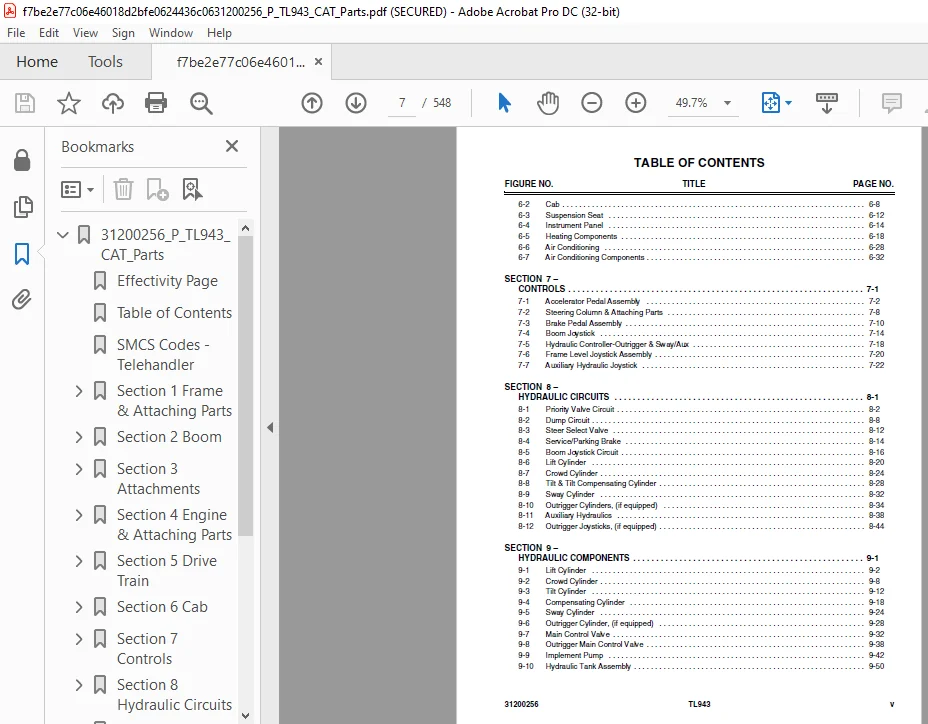
TABLE OF CONTENTS:
Cat TL943 Parts Manual – PDF DOWNLOAD
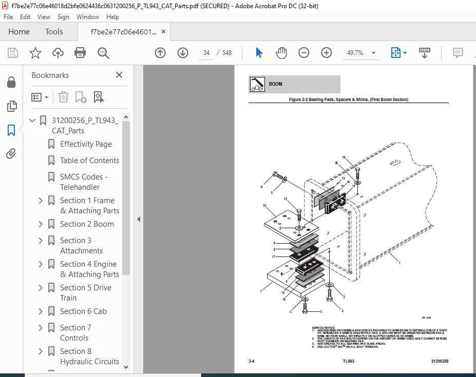
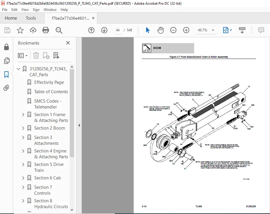
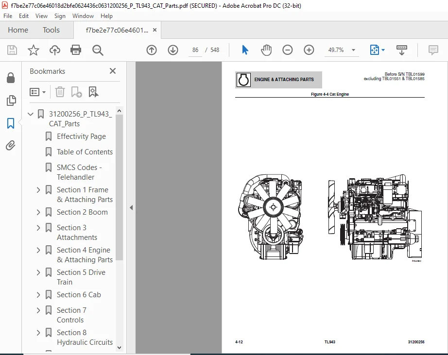
31200256_P_TL943_CAT_Parts.................................................  1
	Effectivity Page.......................................................  3
	Table of Contents......................................................  5
	SMCS Codes - Telehandler............................................... 11
	Section 1 Frame & Attaching Parts...................................... 17
		Figure 1-1 Frame Shrouding & Trim.................................. 18
		Figure 1-2 Axle Mounting........................................... 26
		Figure 1-3 Outrigger Mounting, (if equipped)....................... 28
	Section 2 Boom......................................................... 31
		Figure 2-1 First Boom Section...................................... 32
		Figure 2-2 Bearing Pads, Spacers & Shims, (First Boom Section)..... 34
		Figure 2-3 Second Boom Section..................................... 36
		Figure 2-4 Bearing Pads, Spacers & Shims, (Second Boom Section).... 38
		Figure 2-5 Third Boom Section...................................... 40
		Figure 2-6 Bearing Pads, Spacers & Shims, (Third Boom Section)..... 42
		Figure 2-7 Push Beam/Extend Chain & Roller Assembly................ 44
		Figure 2-8 Quick Coupling Assembly................................. 46
		Figure 2-9 Hydraulic Quick Coupling Assembly....................... 48
	Section 3 Attachments.................................................. 51
		Figure 3-1 Carriage Assembly....................................... 52
		Figure 3-2 Forks................................................... 54
		Figure 3-3 Winch Installation...................................... 56
		Figure 3-4 Fork Mounted Platform................................... 58
		Figure 3-5 Side Tilt Carriage Assembly............................. 62
		Figure 3-6 Fork Clamp Installation................................. 64
		Figure 3-7 Fork Mounted Hook....................................... 66
		Figure 3-8 100 Degree Swing Carriage............................... 68
		Figure 3-9 48” Side Shift Carriage................................. 70
		Figure 3-10 Dual Fork Positioning Carriage......................... 72
	Section 4 Engine & Attaching Parts..................................... 75
		Figure 4-1 Engine Assembly, LH View................................ 76
		Figure 4-2 Engine Assembly, RH View................................ 80
		Figure 4-3 Engine Assembly......................................... 82
		Figure 4-4 Cat Engine.............................................. 86
		Figure 4-5 Fuel Tank & Lines....................................... 90
		Figure 4-6 Radiator Assembly....................................... 92
		Figure 4-7 Air Cleaner & Installation.............................. 96
		Figure 4-8 Exhaust Installation....................................100
		Figure 4-9 Transmission - ZF Transmission..........................105
		Figure 4-10 ZF Transmission - Transmission Converter & Input.......107
		Figure 4-11 ZF Transmission - Gearbox Housing......................109
		Figure 4-12 ZF Transmission - Forward Gear.........................111
		Figure 4-13 ZF Transmission - Reverse Gear Group...................113
		Figure 4-14 ZF Transmission - 1st Shaft Group......................115
		Figure 4-15 ZF Transmission - 2nd Shaft Group......................117
		Figure 4-16 ZF Transmission - 3rd Shaft Group......................119
		Figure 4-17 ZF Transmission - 4th Shaft Group......................121
		Figure 4-18 ZF Transmission - Power Take-Off.......................123
		Figure 4-19 ZF Transmission - Control Unit & Pressure Regulator....125
		Figure 4-20 ZF Transmission - Gearshift System.....................127
		Figure 4-21 ZF Transmission - Oil Pump, Filter & Dipstick..........129
		Figure 4-22 ZF Transmission - Transfer Box.........................131
	Section 5 Drive Train..................................................134
		Figure 5-1 Front Axle Assembly.....................................135
		Figure 5-2 Front Axle..............................................137
		Figure 5-3 Front Axle Housing Assembly.............................139
		Figure 5-4 Front Steering Components...............................141
		Figure 5-5 Front Gear Components...................................143
		Figure 5-6 Front Differential......................................145
		Figure 5-7 Front Double Joint......................................147
		Figure 5-8 Front Brakes............................................149
		Figure 5-9 Front Wheel Hub.........................................151
		Figure 5-10 Front Reduction Gears..................................153
		Figure 5-11 Rear Axle Assembly.....................................155
		Figure 5-12 Rear Axle..............................................157
		Figure 5-13 Rear Axle Housing Assembly.............................159
		Figure 5-14 Rear Steering Components...............................161
		Figure 5-15 Rear Gear Components...................................163
		Figure 5-16 Rear Differential......................................165
		Figure 5-17 Rear Double Joint......................................167
		Figure 5-18 Rear Brakes............................................169
		Figure 5-19 Rear Wheel Hub.........................................173
		Figure 5-20 Rear Reduction Gears...................................175
		Figure 5-21 Rear Axle..............................................177
		Figure 5-22 Central Housing And Steering...........................179
		Figure 5-23 Differential...........................................181
		Figure 5-24 Hub Reduction..........................................183
		Figure 5-25 Brakes.................................................187
		Figure 5-26 Drive Shaft Assembly...................................189
		Figure 5-27 Tires & Rims...........................................191
	Section 6 Cab..........................................................196
		Figure 6-1 Cab Assembly............................................197
		Figure 6-2 Cab.....................................................203
		Figure 6-3 Suspension Seat.........................................207
		Figure 6-4 Instrument Panel........................................209
		Figure 6-5 Heating Components......................................213
		Figure 6-6 Air Conditioning........................................223
		Figure 6-7 Air Conditioning Components.............................227
	Section 7 Controls.....................................................236
		Figure 7-1 Accelerator Pedal Assembly..............................237
		Figure 7-2 Steering Column & Attaching Parts.......................243
		Figure 7-3 Brake Pedal Assembly....................................245
		Figure 7-4 Boom Joystick...........................................249
		Figure 7-5 Hydraulic Controller-Outrigger & Sway/Aux...............253
		Figure 7-6 Frame Level Joystick Assembly...........................255
		Figure 7-7 Auxiliary Hydraulic Joystick............................257
	Section 8 Hydraulic Circuits...........................................260
		Figure 8-1 Priority Valve Circuit..................................261
		Figure 8-2 Dump Circuit............................................267
		Figure 8-3 Steer Select Valve......................................271
		Figure 8-4 Service/Parking Brake...................................273
		Figure 8-5 Boom Joystick Circuit...................................275
		Figure 8-6 Lift Cylinder...........................................279
		Figure 8-7 Crowd Cylinder..........................................283
		Figure 8-8 Tilt & Tilt Compensating Cylinder.......................287
		Figure 8-9 Sway Cylinder...........................................291
		Figure 8-10 Outrigger Cylinders, (if equipped).....................293
		Figure 8-11 Auxiliary Hydraulics...................................297
		Figure 8-12 Outrigger Joysticks, (if equipped).....................303
	Section 9 Hydraulic Components.........................................308
		Figure 9-1 Lift Cylinder...........................................309
		Figure 9-2 Crowd Cylinder..........................................315
		Figure 9-3 Tilt Cylinder...........................................319
		Figure 9-4 Compensating Cylinder...................................325
		Figure 9-5 Sway Cylinder...........................................331
		Figure 9-6 Outrigger Cylinder, (if equipped).......................335
		Figure 9-7 Main Control Valve......................................339
		Figure 9-8 Outrigger Main Control Valve............................345
		Figure 9-9 Implement Pump..........................................349
		Figure 9-10 Hydraulic Tank Assembly................................357
		Figure 9-11 Brake Valve............................................361
		Figure 9-12 Brake Control Valve....................................369
		Figure 9-13 Steer Select Valve.....................................371
		Figure 9-14 Quick Coupler Cylinder.................................373
		Figure 9-15 Outrigger Control Valve................................377
		Figure 9-16 Swing Carriage Cylinder................................381
		Figure 9-17 Side Shift Carriage Cylinder...........................383
		Figure 9-18 Hydraulic Manifold.....................................385
		Figure 9-19 Divertor Valve.........................................387
		Figure 9-20 Dual Fork Positioning Carriage Cylinder................391
	Section 10 Electrical..................................................394
		Figure 10-1 Battery & Cables.......................................395
		Figure 10-2 Battery Disconnect Installation........................399
		Figure 10-3 Engine Harness.........................................403
		Figure 10-4 Transmission Harness...................................409
		Figure 10-5 Transmission Harness - ZF..............................411
		Figure 10-6 Boom Work Light Harness................................413
		Figure 10-7 Cab Work Light Harness.................................415
		Figure 10-8 Work Light Cab Harness.................................417
		Figure 10-9 Work Light Cab Harness, (if equipped)..................419
		Figure 10-10 Frame Road Lights Harness.............................421
		Figure 10-11 Cab Road Lights Harness...............................423
		Figure 10-12 Auxiliary Electrics...................................425
		Figure 10-13 A/C Harness...........................................427
		Figure 10-14 Cab Harness...........................................429
		Figure 10-15 Power Distribution Box Installation...................431
		Figure 10-16 Transmission Relay Harness............................433
		Figure 10-17 Cab Road Lights Harness...............................435
		Figure 10-18 Tilt On Joystick Harness..............................437
		Figure 10-19 Tilt & Aux Control Module.............................439
		Figure 10-20 Accessory Module Harness..............................441
		Figure 10-21 Chassis Harness.......................................443
		Figure 10-22 Cab Options Harness...................................447
		Figure 10-23 VEC Options Harness...................................449
	Section 11 Decals......................................................454
		Figure 11-1 Cab & Frame Decals.....................................455
		Figure 11-2 Boom Decals............................................467
	Section 12 Options.....................................................470
		Figure 12-1 Block Heater Installation..............................471
		Figure 12-2 8” Winch...............................................473
		Figure 12-3 Winch Motor............................................477
		Figure 12-4 Pressure Reducer Valve, 1360 PSI.......................479
		Figure 12-5 Pintle Hook............................................481
		Figure 12-6 Fender Installation....................................483
		Figure 12-7 Work Light Package.....................................485
		Figure 12-8 Beacon Light Package...................................498
		Figure 12-9 Boom Lights Installation...............................502
		Figure 12-10 Skylight Wiper Assembly...............................504
		Figure 12-11 Road Lights Installation..............................506
		Figure 12-12 Cold Weather Package..................................512
		Figure 12-13 Arctic Package........................................514
		Figure 12-14 Top Cab Glass Shield..................................518
		Figure 12-15 Front Cab Glass Shield................................520
		Figure 12-16 Hydraulic Cooler Bypass Installation..................522
		Figure 12-17 Beacon Light Mount With AC............................524
		Figure 12-18 Winch.................................................526
	Maintenance Parts List.................................................529
	Part Number Index......................................................533
CAT TL943 PARTS MANUAL – PDF DOWNLOAD:
IMAGES PREVIEW OF THE MANUAL:


PLEASE NOTE:
- This is the SAME manual used by the dealers to troubleshoot any faults in your vehicle. This can be yours in 2 minutes after the payment is made.
- Contact us at [email protected] should you have any queries before your purchase or that you need any other service / repair / parts operators manual.
S.M