Trusted Business
Verified & Licensed
Virus Free Files
100% Safe Downloads
Secure Payment
SSL Protected
Instant Delivery
Available Immediately
CAT Unit Rig Mining Truck WD-4-S1 Wheel Dolly Operation & Maintenance Manual BI007313 – PDF DOWNLOAD
$28.95
CAT Unit Rig Mining Truck WD-4-S1 Wheel Dolly Operation & Maintenance Manual BI007313 – PDF DOWNLOAD
Instant PDF Download
Available immediately
Save to Your Device
Download & keep forever
Antivirus Scanned
100% virus-free
Trusted Worldwide
175,000+ customers
Description
CAT Unit Rig Mining Truck WD-4-S1 Wheel Dolly Operation & Maintenance Manual BI007313 – PDF DOWNLOAD
FILE DETAILS:
CAT Unit Rig Mining Truck WD-4-S1 Wheel Dolly Operation & Maintenance Manual BI007313 – PDF DOWNLOAD
Language : English
Pages : 194
Downloadable : Yes
File Type : PDF
IMAGES PREVIEW OF THE MANUAL:
DESCRIPTION:
CAT Unit Rig Mining Truck WD-4-S1 Wheel Dolly Operation & Maintenance Manual BI007313 – PDF DOWNLOAD
INTRODUCTION:
- The purpose of this manual is to provide an understanding of the WD-4-SI Wheel Dolly. The WD-4SI is designed to facilitate removal and installation of motorized wheels, front wheels, and front suspension.
- Removal and installation procedures are not provided in this manual. Refer to applicable vehicle maintenance manual for item being removed or replaced.
DESCRIPTION:
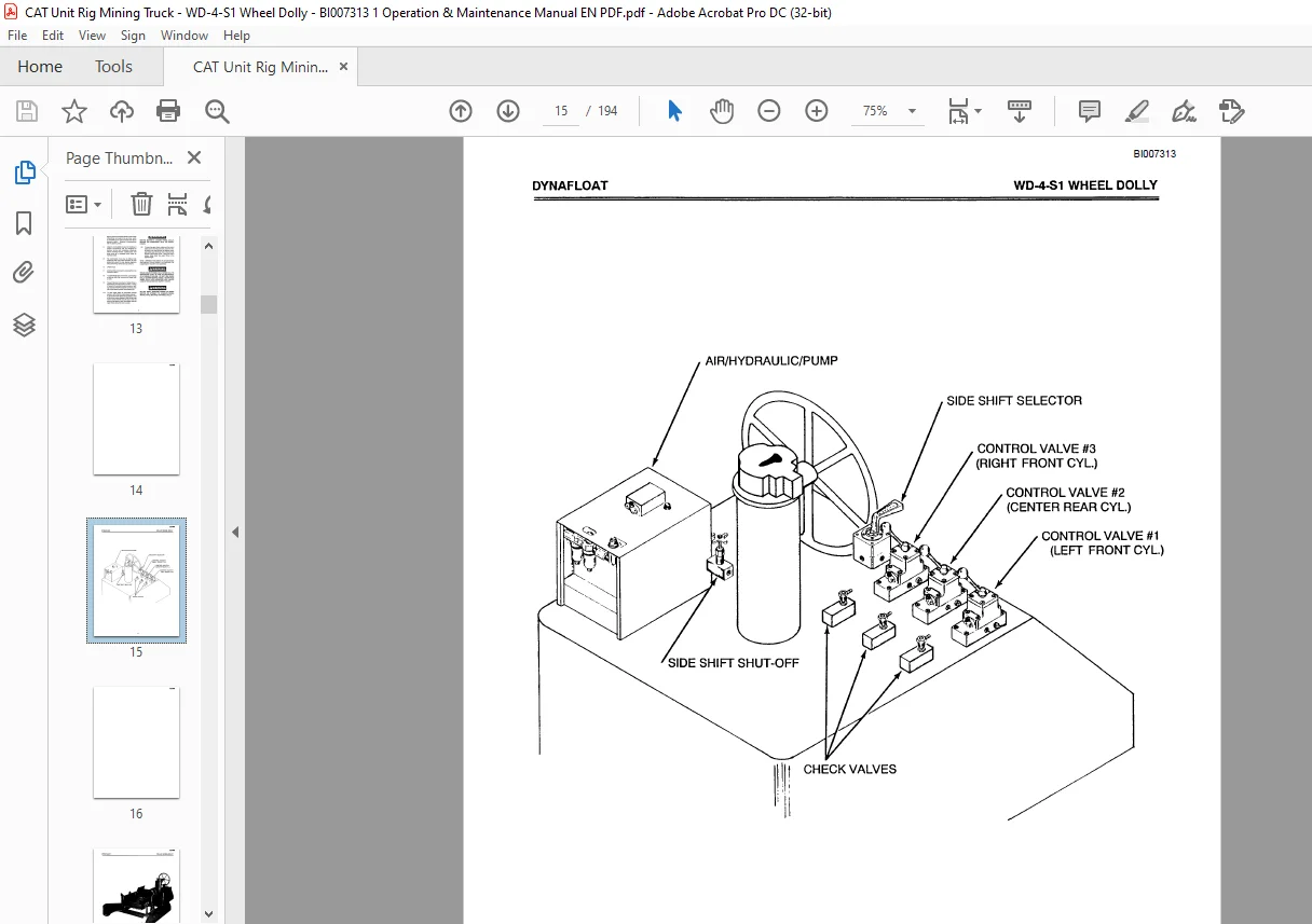
1-2. The Wheel Dolly consists of a main frame with three built-in 15 ton (13.6 tonne) rams for
lifting and alignment. A hydraulic pump located at the
operator’s station, provides 1o 000 psi (69 000
kPa) for ram operation. Shut-off valves and manually operated check valves are used
to control raising and lowering of upper frame. Four-way valve and two stage hydraulic
cylinder are used to control side shifting of the upper frame.
lifting and alignment. A hydraulic pump located at the
operator’s station, provides 1o 000 psi (69 000
kPa) for ram operation. Shut-off valves and manually operated check valves are used
to control raising and lowering of upper frame. Four-way valve and two stage hydraulic
cylinder are used to control side shifting of the upper frame.
1-3. Drive power for the Wheel Dolly is standard shop air which is connected to the air
inlet on the Wheel Dolly and routed to the air motor, which is controlled by the manual throttle
lever at the operators station. Steering is accomplished with the steering wheel.
inlet on the Wheel Dolly and routed to the air motor, which is controlled by the manual throttle
lever at the operators station. Steering is accomplished with the steering wheel.
1-4. Adaptors are available to allow for handling of vehicle components and are designed
to facilitate removal and installation procedures without removing fenders, superstructure,
and dump body as is necessary when using an overhead crane.
to facilitate removal and installation procedures without removing fenders, superstructure,
and dump body as is necessary when using an overhead crane.
1-5. The combination of air drive for Wheel Dolly positioning and upper frame operation
for load positioning; allows for safe, precise alignment when performing maintenance procedures.
for load positioning; allows for safe, precise alignment when performing maintenance procedures.
1-6. OPERATION
1-7. All Wheel Dolly movement is controlled from the operator’s station.
1-8. To initiate Wheel Dolly movement, connect shop air (80 psi (550 kPa) minimum) to Wheel
Dolly air inlet
Dolly air inlet
1-9. Forward-Reverse movement of Wheel Dolly is controlled by the three position throttle.
Pushing it Forward (F) provides forward movement, pull ing it back provides Reverse (R) movement,
with the middle detent position being Neutral (N).
Pushing it Forward (F) provides forward movement, pull ing it back provides Reverse (R) movement,
with the middle detent position being Neutral (N).
1-10. To raise upper frame to component removal position, verify that the control valves
(valves 1, 2, and 3) are in the canter HOLD position, close all the check valves directly in front
of the three control valves and the shut-off valve in the line going to the selector valve, and
slowly raise the upper frame using the control valves.
(valves 1, 2, and 3) are in the canter HOLD position, close all the check valves directly in front
of the three control valves and the shut-off valve in the line going to the selector valve, and
slowly raise the upper frame using the control valves.
TABLE OF CONTENTS:
CAT Unit Rig Mining Truck WD-4-S1 Wheel Dolly Operation & Maintenance Manual BI007313 – PDF DOWNLOAD
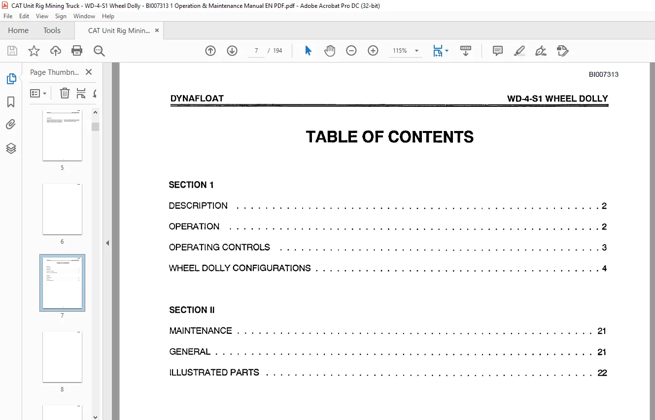
SECTION 1
DESCRIPTION 2
OPERATION 2
OPERATING CONTROLS 3
WHEEL DOLLY CONFIGURATIONS 4
SECTION II
MAINTENANCE 21
GENERAL 21
ILLUSTRATED PARTS 22
Contact us: [email protected]
https://vimeo.com/888364775?share=copy
S.V