CAT Voith Turbo Couplings with Constant Fill for Operating Medium Water Installation & Operating Manual 3626-011300 – PDF DOWNLOAD
$20.95
CAT Voith Turbo Couplings with Constant Fill for Operating Medium Water Installation & Operating Manual 3626-011300 – PDF DOWNLOAD
Description
CAT Voith Turbo Couplings with Constant Fill for Operating Medium Water Installation & Operating Manual 3626-011300 – PDF DOWNLOAD
FILE DETAILS:
CAT Voith Turbo Couplings with Constant Fill for Operating Medium Water Installation & Operating Manual 3626-011300 – PDF DOWNLOAD
Language : English
Pages : 84
Downloadable : Yes
File Type : PDF
IMAGES PREVIEW OF THE MANUAL:
DESCRIPTION:
CAT Voith Turbo Couplings with Constant Fill for Operating Medium Water Installation & Operating Manual 3626-011300 – PDF DOWNLOAD
Preface:
3.1 General information:
This manual will support you in using this turbo coupling in a safe, proper and economical way.
If you observe the information contained in this manual, you will
– increase the reliability and lifetime of coupling and installation,
– avoid any risks,
– reduce repairs and downtimes.
This manual must
– always be available at the machine site,
– be read and used by every person who works on the coupling.
The coupling is manufactured to the latest design standards and approved safety regulations.
Nevertheless, the user’s or third parties life may be endangered or the machine or
other material assets impaired in case of improper handling or use.
- Spare parts must comply with the requirements determined by Voith. This is guaranteed in case of
original spare parts, as these are subject to regular quality control according to DIN ISO 9001 /
EN 29001. - Spare parts from other suppliers may, under circumstances, change the characteristics of
the unit and lead to substantial defects, for which Voith cannot assume responsibility. - For repair, only use appropriate workshop equipment. Professional
maintenance or repair can only be guaranteed by the manufacturer.
TABLE OF CONTENTS:
CAT Voith Turbo Couplings with Constant Fill for Operating Medium Water Installation & Operating Manual 3626-011300 – PDF DOWNLOAD
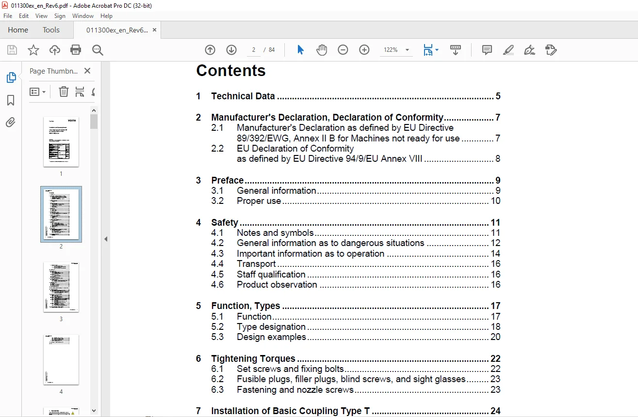
Installation and Operating Manual...................................................................................... 1
1 Technical Data....................................................................................................... 5
2 Manufacturer's Declaration, Declaration of Conformity................................................................ 7
	2.1 Manufacturer's Declaration as defined by EU Directive 89/392/EWG, Annex II B for Machines not ready for use.... 7
	2.2 EU Declaration of Conformity as defined by EU Directive 94/9/EU Annex VIII..................................... 8
3 Preface.............................................................................................................. 9
	3.1 General information............................................................................................ 9
	3.2 Proper use.....................................................................................................10
4 Safety...............................................................................................................11
	4.1 Notes and symbols..............................................................................................11
	4.2 General information as to dangerous situations.................................................................12
	4.3 Important information as to operation..........................................................................14
	4.4 Transport......................................................................................................16
	4.5 Staff qualification............................................................................................16
	4.6 Product observation............................................................................................16
5 Function, Types......................................................................................................17
	5.1 Function.......................................................................................................17
	5.2 Type designation...............................................................................................18
	5.3 Design examples................................................................................................20
6 Tightening Torques...................................................................................................22
	6.1 Set screws and fixing bolts....................................................................................22
	6.2 Fusible plugs, filler plugs, blind screws, and sight glasses...................................................23
	6.3 Fastening and nozzle screws....................................................................................23
7 Installation of Basic Coupling Type T................................................................................24
	7.1 As delivered condition.........................................................................................24
	7.2 Preparation....................................................................................................24
	7.3 Mounting.......................................................................................................26
	7.4 Mounting devices...............................................................................................28
8 Installation of Basic Coupling Type TN...............................................................................29
	8.1 As delivered condition.........................................................................................29
	8.2 Mounting.......................................................................................................30
9 Alignment............................................................................................................31
	9.1 Flexible connecting couplings..................................................................................31
	9.2 Laid lengths and type allocations turbo coupling / flexible connecting coupling................................33
	9.3 Alignment tolerances...........................................................................................33
	9.4 Alignment......................................................................................................34
10 Operating Fluids....................................................................................................36
	10.1 Special requirements to be fulfilled by the operating fluid...................................................36
	10.2 Grease supply for turbo couplings with centrifugal valves (types T…F…)........................................36
11 Fill, Level Check and Draining......................................................................................38
	11.1 Coupling fill.................................................................................................39
	11.2 Level check...................................................................................................40
	11.3 Draining the coupling.........................................................................................41
12 Commissioning.......................................................................................................42
13 Maintenance.........................................................................................................44
	13.1 Outside cleaning..............................................................................................45
	13.2 Flexible connecting coupling..................................................................................46
	13.3 Bearings......................................................................................................47
	13.4 Fusible plugs.................................................................................................48
	13.5 Arrangement of fusible plugs..................................................................................48
14 Assembly Control and Maintenance Report.............................................................................49
	14.1 Assembly control report.......................................................................................50
	14.2 Maintenance report............................................................................................52
15 Coupling Disassembly................................................................................................54
	15.1 Preparation...................................................................................................54
	15.2 Removal.......................................................................................................55
	15.3 Mechanical removal devices....................................................................................56
	15.4 Hydraulic removal devices.....................................................................................57
16 Trouble Shooting – Remedy...........................................................................................58
17 Queries, Orders placed for Service Engineers and Spare Parts........................................................61
18 Temperature Monitoring..............................................................................................62
	18.1 MTS mechanical thermal switch unit for pre-warning............................................................62
	18.2 BTS non-contacting thermal switch unit........................................................................63
19 Spare Parts Information Turbo Couplings.............................................................................66
	19.1 Storage.......................................................................................................66
	19.2 Spare parts for types 274 DTW/DTWV............................................................................67
	19.3 Spare parts for types TW and TWN..............................................................................68
	19.4 Spare parts for types TWV/TWVV and TWVN/TWVVN.................................................................70
	19.5 Spare parts for types TWVVS and TWVVSN........................................................................72
20 Spare parts information Connecting couplings........................................................................74
	20.1 Connecting couplings on the input side........................................................................74
	20.2 Connecting coupling on the output side........................................................................75
21 Representations Voith Turbo GmbH & Co. KG...........................................................................79
22 Index...............................................................................................................82
Contact us: [email protected]
https://vimeo.com/888367268?share=copy
S.V