Caterpillar EC25K Lift Truck Service Manuals – PDF DOWNLOAD
Original price was: $89.95.$29.95Current price is: $29.95.
Caterpillar EC25K Lift Truck Service Manuals – PDF DOWNLOAD
All S/N & Models covered
Description
Caterpillar EC25K Lift Truck Service Manuals – PDF DOWNLOAD
FILE DETAILS:
Caterpillar EC25K Lift Truck Service Manuals – PDF DOWNLOAD
Brand: CAT – Caterpillar
Type of machine: Forklift Truck
Type of document: Service Manuals
Model: CAT EC25K
Content:
– 19 Items PDF
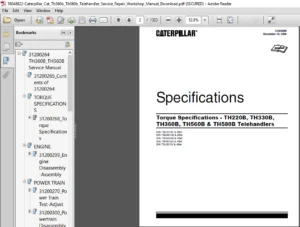
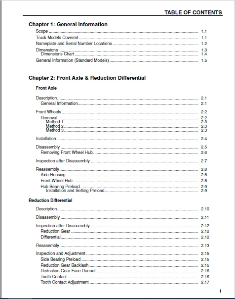
TABLE OF CONTENTS:
Caterpillar EC25K Lift Truck Service Manuals – PDF DOWNLOAD
Caterpillar EC15K EC18K EC18KL Chassis & Mast Service Manual
Chapter 1: General Information
Scope 1 1
Truck Models Covered 1 1
Nameplate and Serial Number Locations 1 2
Dimensions 1 3
Dimensions Chart 1 4
General Information (Standard Models) 1 5
Chapter 2: Front Axle & Reduction Differential
Front Axle
Description 2 1
General Information 2 1
Front Wheels 2 2
Removal 2 2
Method 1 2 3
Method 2 2 3
Method 3 2 3
Installation 2 4
Disassembly 2 5
Removing Front Wheel Hub 2 6
Inspection after Disassembly 2 7
Reassembly 2 8
Axle Housing 2 8
Front Wheel Hub 2 8
Hub Bearing Preload 2 9
Installation and Setting Preload 2 9
Reduction Differential
Description 2 10
Disassembly 2 11
Inspection after Disassembly 2 12
Reduction Gear 2 12
Differential 2 12
Reassembly 2 13
Inspection and Adjustment 2 15
Side Bearing Preload 2 15
Reduction Gear Backlash 2 15
Reduction Gear Face Runout 2 16
Tooth Contact 2 16
Tooth Contact Adjustment 2 17
ii
TABLE OF CONTENTS
Chapter 3: Transfer Assembly
Description 3 1
Disassembly 3 2
Disassembly Sequence 3 2
Inspection after Disassembly 3 2
Reassembly 3 5
Chapter 4: Rear Axle
Description 4 1
Rear Wheels 4 2
Removal 4 2
Installation 4 4
Rear Axle 4 7
Removal 4 7
Installation 4 8
Disassembly 4 9
Inspection after Disassembly 4 11
Reassembly 4 12
Inspection and Adjustment 4 17
Minimum Turning Radius Adjustment 4 17
Chapter 5: Brake System
Description 5 1
Automatic Adjusting Device 5 1
General Information 5 1
Master Cylinder
Disassembly 5 2
Inspection after Disassembly 5 3
Reassembly 5 3
Service Brakes
Disassembly
(EC15K – 18KL) 5 4
(EC20K – 30KL) 5 5
Inspection after Disassembly 5 7
Reassembly
(EC15K – 18KL) 5 8
(EC20K – 30KL) 5 9
Wheel Cylinders
Disassembly 5 12
Inspection after Disassembly 5 13
Reassembly 5 13
Inspection and Adjustment 5 14
iii
TABLE OF CONTENTS
Chapter 6: Steering System
Steering System
Description 6 1
Steering System 6 1
Oil Flow Sequence 6 1
General Information 6 1
Steering Gear
Steering Wheel
Removal 6 2
Installation 6 2
Steering Gear 6 3
Inspection after Removal 6 4
Disassembly 6 5
Working Rules and Tips 6 6
Suggestions 6 6
Inspection after Disassembly 6 6
Reassembly 6 7
Suggestions 6 8
Steer Pump
Removal 6 9
Installation 6 10
Disassembly 6 11
Sequence 6 11
Working Rules and Tips 6 12
Suggestions 6 12
Inspection after Disassembly 6 14
Reassembly 6 15
Sequence 6 15
Suggestions 6 16
Inspection after Reassembly 6 18
Chapter 7: Hydraulic System
Hydraulic System
Description 7 1
Schematic 7 1
Hydraulic Tank 7 2
Hydraulic Pump 7 3
Control Valve 7 5
Lift and Tilt Cylinders 7 6
Flow Regulator Valve 7 7
Down Safety Valve 7 8
Removal and Installation Warning 7 9
iv
TABLE OF CONTENTS
Chapter 7: Hydraulic System, continued
Hydraulic Pump
Removal 7 10
Installation 7 11
Disassembly 7 12
Working Rules and Tips 7 13
Suggestions 7 14
Inspection after Disassembly 7 16
Body 7 16
Mounting Flange Face 7 16
Bushes and Balance Plate 7 16
Gears 7 16
Reassembly 7 17
Inspection after Reassembly 7 22
Control Valve
Removal 7 23
Installation 7 24
Disassembly 7 25
Suggestions 7 27
Reassembly 7 27
Lift and Tilt Cylinders
Removal
Lift Cylinders 7 28
Tilt Cylinders 7 31
Disassembly
Lift Cylinders 7 33
Tilt Cylinders 7 34
Flow Regulator Valve 7 35
Inspection after Disassembly 7 36
Precautions for Reassembly 7 36
Inspection and Adjustment
Hydraulic Tank 7 37
Control Valve 7 38
Lift and Tilt Cylinders 7 40
Adjusting Method 7 41
Testing 7 42
Chapter 8: Mast and Forks
Description 8 1
Removal and Installation 8 2
Disassembly 8 4
Inspection after Disassembly 8 6
Reassembly 8 7
Inspection and Adjustment 8 8
Forks 8 8
Chain Tension Adjustment 8 9
Clearance Adjustment on Lift Bracket 8 10
Mast Clearance Adjustment 8 13
Main Roller Shim Replacement 8 15
Mast Strip Adjustment 8 15
Tilt Angle Adjustment 8 16
Lift Cylinder Stroke Adjustment 8 17
Bleeding Lift Cylinders 8 17
Service Data 8 19
Troubleshooting 8 20
Chapter 9: Troubleshooting Section
Front Axle and Reduction Differential 9 1
Brake System 9 2
Steering System 9 4
Hydraulic System 9 6
Rear Axle 9 8
Mast and Forks 9 9
vi
TABLE OF CONTENTS
Chapter 10: Maintenance Service Data
Maintenance Service Data 10 1
Front Axle and Reduction Differential 10 1
Transfer Case 10 3
Rear Axle 10 4
Brake System 10 6
Steering System, 10 11
Hydraulic System 10 13
Mast and Forks (Simplex Mast) 10 16
Tightening Torques for Standard Bolts and Nuts 10 18
Fine Thread—With Spring Washer 10 18
Fine Thread—Without Spring Washer 10 19
Coarse Thread—With Spring Washer 10 20
Coarse Thread—With Spring Washer 10 21
Maintenance Chart 10 22
Planned Replacement Parts 10 28
Lubrication Information 10 29
Chart 10 29
Lubricant Specifications 10 30
Recommended Brands of Lubrications 10 30
Weight of Major Components (Approximate) 10 31
Special Service Tools 10 32
Special Tool Illustrations 10 33
Inspection Guide 10 36
Caterpillar EC15K EC18K EC18KL GE SX Controls Service Manual
1 GENERAL INFORMATION & FEATURES
Glossary 1-1
Motor Options 1-5
Nameplate and Serial Number Locations 1-6
Features of the Control System 1-7
Basics of Circuit Operation 1-8
Standard Display 1-17
Premium Display 1-18
Premium Display Set up Modes 1-19
Vehicle Monitoring System 1-20
Traction Control Logic Flow Chart 1-21
General Maintenance Instructions 1-22
General Trouble Shooting Instructions 1-24
2 PROGRAMMING
Handset 2-1
Operation 2-2
GE Sentry Set-up Procedures 2-2
Function Settings 2-4
Controller Setup 2-15
Traction Controller Settings 2-16
Accelerator Setup 2-23
Pump Controller Settings 2-25
Memory Maps 2-30
Speedometer Setup 2-34
3 CHECKS & REPAIRS
General Information 3-1
Fuses 3-2
Exploded View of Contactor 3-3
Contactor Repair 3-4
Truck Management Module 3-5
Thermal Transfer 3-6
Traction Control 3-10
Trouble Shooting Tips (Motors) 3-11
Unsatisfactory Brush Performance 3-12
Commutator Surfaces Conditions 3-18
4 SX CONTROL CONNECTIONS & TROUBLESHOOTING
BY SYMPTOM
SX Control 4-1
Failures that Cause Reduced or No Motor Torque 4-2
Misoperation of Other Features 4-5
TABLE OF CONTENTS
5 WIRING
Traction Bypass with Pump Contactor Schematic 5-1
Pump Contactor Schematic 5-3
Traction Bypass with Pump Contactor Schematic 5-5
Traction Bypass with Pump Control Schematic 5-7
Pump Control Schematic 5-9
Traction Motor Controller with Pump motor Controller and Bypass 5-11
Voltage Checks 5-13
TMM7A (Truck Management Module) 5-16
Pump Driver 5-18
Pump Time Delay 5-19
6 DIAGNOSTIC STATUS CODES
Basic Checks 6-1
Status Codes 6-2
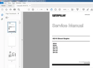
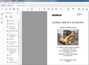
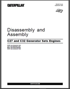
IMAGES PREVIEW OF THE MANUAL:
CATERPILLAR EC25K LIFT TRUCK SERVICE MANUALS – PDF DOWNLOAD:
PLEASE NOTE:
- This is the SAME manual used by the dealers to troubleshoot any faults in your vehicle. This can be yours in 2 minutes after the payment is made.
- Contact us at [email protected] should you have any queries before your purchase or that you need any other service / repair / parts operators manual.
S.V