Caterpillar EC55N Lift Truck Service Manual – PDF DOWNLOAD
Original price was: $89.95.$25.95Current price is: $25.95.
Caterpillar EC55N Lift Truck Service Manual – PDF DOWNLOAD
Description
Caterpillar EC55N Lift Truck Service Manual – PDF DOWNLOAD
DESCRIPTION:
Caterpillar EC55N Lift Truck Service Manual – PDF DOWNLOAD
Cat® Lift Trucks
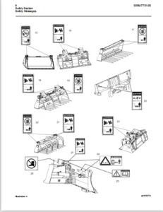
Important Safety Information :
Most accidents involving product operation, maintenance and repair are caused by failure to observe basic safety rules and precautions. An accident can often be avoided by recognizing potentially hazardous situations before an accident occurs. A person must be alert to potential hazards.
- This person should also have the necessary training, skills and tools to perform these functions properly. Improper operation, lubrication, maintenance or repair of this product can be dangerous and could result in injury or death.
- Do not operate or perform any lubrication, maintenance or repair on this product, until you have read and understood the operation, lubrication, maintenance and repair information. Safety precautions and warnings are provided in this manual and on the product. If these hazard warnings are not heeded, bodily injury or death could occur to you or other persons. The hazards are identified by the “Safety Alert Symbol” and followed by a “Signal Word” such as “CAUTION” or “WARNING” as shown below.
TABLE OF CONTENTS:
Caterpillar EC55N Lift Truck Service Manual – PDF DOWNLOAD
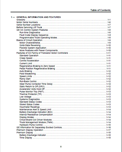
1 — GENERAL INFORMATION AND FEATURES
Glossary 1-1
Motor Serial Numbers 1-6
Serial Number Locations 1-7
Before Servicing Lift Truck 1-7
GE SX Control System Features 1-8
Run-time Diagnostics 1-8
Fault Code Display Sequence 1-8
Programmable Truck Operating Modes 1-8
Basics of Circuit Operation 1-9
Motor Characteristics 1-9
Solid-State Reversing 1-10
Flexible System Application 1-10
More Features with Fewer Components 1-10
Features of SX Family of Transistor Motor Controllers 1-11
Standard Operation 1-11
Creep Speed 1-11
Control Acceleration 1-11
Current Limit 1-11
Regenerative Braking to Zero Speed 1-11
Pedal Position Regenerative Braking 1-11
Auto Braking 1-12
Field Weakening 1-12
Speed Limits 1-12
Ramp Start 1-12
Roll-Back Control 1-12
Steer Pump Contactor Time Delay 1-12
Static Return to Off (SRO) 1-12
Accelerator Volts Hold Off 1-12
Pulse Monitor Trip (PMT) 1-13
Thermal Protector (TP) 1-13
Low Voltage 1-13
Systems Diagnostics 1-13
Standard Status Codes 1-13
Stored Status Codes 1-13
Hourmeter Readings 1-13
Maintenance Alert & Speed Limit 1-14
Battery Discharge Indication (BDI) 1-14
Internal Resistance Compensation 1-14
Display Modes 1-14
Circuit Board Coil Driver Modules 1-14
Truck Management Module (TMM) 1-14
Hydraulic Pump Control 1-15
GE Information for Separately Excited Controls 1-16
Premium Display Operation 1-17
Premium Display 1-18
Battery Discharge Indicator 1-18
Time Display 1-18
iv
Table of Contents
Speed Display 1-18
Hour Meter 1-18
History Display 1-18
Start-Up 1-19
Left Mode Button 1-19
Right Mode Button 1-19
Fault Code Indicator 1-19
Monitoring System Action Lights 1-19
Setup Modes 1-19
Brush Wear Indicator Icon 1-20
Vehicle Monitoring System – Action Lights 1-21
Traction Control Logic Flow Chart For Normal Operating Conditions 1-22
General Maintenance Instructions 1-23
Cabling for Vehicle Retrofits 1-23
RF Interference 1-23
Suppression 1-23
Recommended Lubrication of Pins and Sockets Prior to Installation 1-24
General Troubleshooting Instructions 1-25
BDI Operation 1-25
Function 14 Setting 1-26
2 — PROGRAMMING
Handset General Information 2-1
Handset Functions 2-2
Handset Operation 2-2
Function Set-Up Procedures 2-3
Accessing Stored Fault Codes 2-4
Setup Functions for Traction Controller 2-5
Function 1 – Adjustable Motor EMF For Plugging or Regen 2-5
Function 2 – Creep Speed 2-5
Function 3 – Armature Controlled Acceleration 2-5
Function 4 – Armature Current Limit 2-5
Function 5 – Counter EMF Trip Point For Auto Braking 2-6
Function 6 – Auto Calibration of Accelerator Potentiometer 2-6
Function 7 – Min Field Current 2-6
Function 8 – Max Field Current 2-6
Function 9 – Regen Braking Current Limit 2-6
Function 10 -Max Field Current During Regen 2-7
Function 11 – Brake Switch Current Limit 2-7
Function 12 – Top Speed Limit 2-7
Function 13 -Maintenance and Truck Management Speed Limit 2-7
Function 14 – Internal Resistance Compensation 2-8
Function 15 – Battery Volts 2-8
Function 16 – Stall Protection % On-Time Trip Point 2-8
Function 17 – Card Type Selection 2-9
Function 18 – Steer Pump Time Delay 2-9
Function 19 -Maintenance Code Tens and Units Hours Set 2-9
Function 20 – Code Thousands and Hundreds Hours Set 2-9
Table of Contents
v
Function 21 – Auto Regen Braking Current Limit 2-9
Function 22 – Not Applicable 2-9
Function 23 – Regen Cancel Current 2-10
Function 24 – Field Weakening Start 2-10
Function 25 -Monitor 2-10
Function 26 – Field To Armature Current Ratio 2-10
Function 27 -Minutes Register 2-10
Function 28 – Stored Status Code Count Pointer 2-11
Function 29 – Power Steering Hours (Ones and Tens) 2-11
Function 30 – Power Steering Hours (Hundreds and Thousands) 2-11
Function 48 -Mode 1 Armature Controlled Acceleration 2-11
Function 49 -Mode 1 Regen Current Limit 2-12
Function 50 -Mode 1 Auto Regen Current Limit 2-12
Function 51 -Mode 1 Speed Limit 2-12
Function 52 -Mode 2 Armature Controlled Acceleration 2-12
Function 53 -Mode 2 Regen Current Limit 2-12
Function 54 -Mode 2 Auto Regen Current Limit 2-12
Function 55 -Mode 2 Speed Limit 2-12
Function 56 -Mode 3 Armature Controlled Acceleration 2-12
Function 57 -Mode 3 Regen Current Limit 2-13
Function 58 -Mode 3 Auto Regen Current Limit 2-13
Function 59 -Mode 3 Speed Limit 2 2-13
Function 60 -Mode 4 Armature Controlled Acceleration 2-13
Function 61 -Mode 4 Regen Current Limit 2-13
Function 62 -Mode 4 Auto Regen Current Limit 2-13
Function 63 -Mode 4 Speed Limit 2 2-13
Setup Functions For Hydraulic Pump Control 2-15
Function 1 – Not Applicable 2-15
Function 2 – Internal Resistance Compensation Star 2-15
Function 3 – Controlled Acceleration 2-15
Function 4 – Armature Current Limit 2-15
Function 7 – Internal Resistance Compensation Rate 2-15
Function 11 – Aux 1/Aux 2 Speed Limit (SL1) 2-15
Function 12 – Lift 1 Speed Limit (SL2) 2-15
Function 13 – Tilt Speed Limit (SL3) 2-15
Function 14 – Lift 2 Speed Limit (SL4) 2-16
Function 15 – Not Applicable 2-16
Function 16 – Speed/Torque Compensation 2-16
Function 17 – Card Type Selection 2-16
Function 18 -Overcurrent Setting 2-16
Function 28 – Fault Count Pointer 2-17
Function 48 -Mode 1 – Controlled Acceleration 2-17
Function 49 -Mode 1 – Lift 1 Speed Limit (SL2) 2-17
Function 50 -Mode 1 – Tilt Speed Limit (SL3) 2-18
Function 51 -Mode 1 – Lift 2 Speed Limit (SL4) 2-18
Function 52 -Mode 2 – Controlled Acceleration 2-18
Function 53 -Mode 2 – Lift 1 Speed Limit (SL2) 2-18
Function 54 -Mode 2 – Tilt Speed Limit (SL3) 2-18
vi
Table of Contents
Function 55 -Mode 2 – Lift 2 Speed Limit (SL4) 2-18
Function 56 -Mode 3 – Controlled Acceleration 2-18
Function 57 -Mode 3 – Lift 1 Speed Limit (SL2) 2-18
Function 58 -Mode 3 – Tilt Speed Limit (SL3) 2-18
Function 59 -Mode 3 – Lift 2 Speed Limit (SL4) 2-18
Function 60 -Mode 4 – Controlled Acceleration 2-18
Function 61 -Mode 4 – Lift 1 Speed Limit (SL2) 2-18
Function 62 -Mode 4 – Tilt Speed Limit 3 (SL3) 2-19
Function 63 -Mode 4 – Lift 2 Speed Limit (SL4) 2-19
Setup Procedures 2-20
Controller Setup 2-20
Traction Controller Settings Chart 2-21
Traction Controller Settings Chart For UL EE Closed Motor Option 2-22
Pump Controller Settings Chart 2-23
Memory Maps – Traction Control 2-24
Accelerator Setup 2-27
Premium Display Speedometer Setup 2-28
3 — CHECKS AND REPAIRS
General Information 3-1
Fuses 3-2
Contactor Repair 3-3
Brush Wear Indicators 3-4
Motor Thermal Switches 3-4
Thermal Transfer 3-5
Why is Thermal Transfer important? 3-5
What determines “Good” Thermal Transfer? 3-5
Insuring Proper Thermal Transfer 3-5
Mounting Instructions for Motor Controls 3-5
Necessary Tools 3-6
The Controls 3-6
Vehicle Mounting Surface 3-7
Application of Thermal Compound 3-7
Mounting the Control 3-8
Maintenance 3-8
Traction Control 3-9
Troubleshooting Tips (Motors) 3-10
Successful Commutation Requirements 3-10
Sparking At Brushes 3-10
Insulation System 3-10
Armature Winding Problems 3-10
Unsatisfactory Brush Performance 3-11
Table One – Primary Sources of Unsatisfactory Brush Performance 3-11
Table Two – Indications Appearing at Brushes 3-12
Table Three – Indications Appearing at Heating 3-14
Table Four – Indications Appearing at Commutator Surface 3-15
Commutator Surfaces 3-17
Table of Contents
vii
4 — SX CONTROL CONNECTIONS & TROUBLESHOOTING BY SYMPTOM
SX CONTROL 4-1
Instructions for Removal of SX Control 4-1
Table One – Failures That Cause Reduced or No Motor Torque 4-2
Table Two – Mis-operation of Other Features 4-5
Table Three – Mis-operation of Other Features 4-6
5 — ELECTRICAL
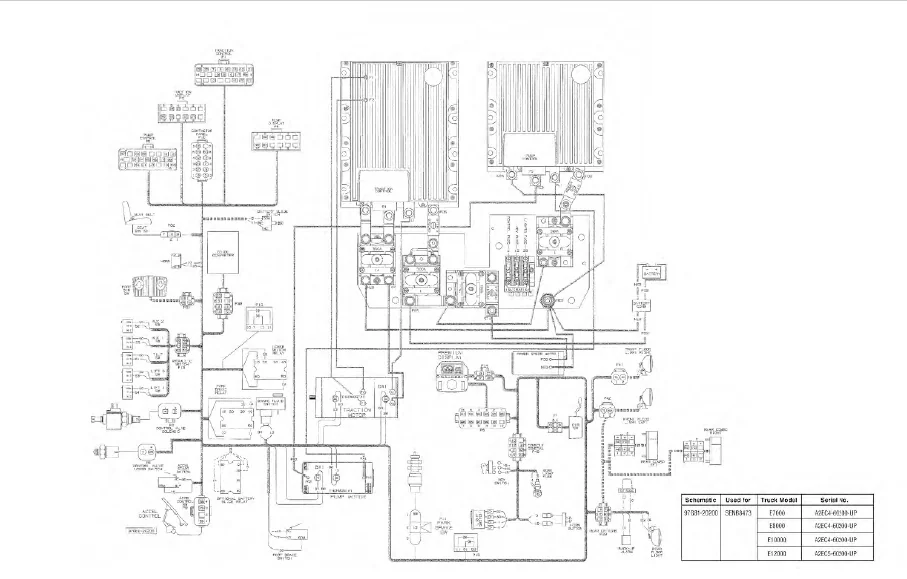
Electrical Wiring Diagram 5-1
Electrical Schematic 5-3
Voltage Checks 5-5
Connections to Main Traction Plug P1 with Controller Hydraulics 5-5
Connections to Main Traction Plug P5 with Controller Hydraulics 5-6
Connections to Main Plug (23 Pin) and P2 or P4 Plug (12 Pin) 5-7
Pump Driver 5-8
Shorted or Open Field or Armature FET Test 5-9
Description 5-9
Armature FET Test 5-9
Field FET Test 5-9
6 — DIAGNOSTIC STATUS CODES
Basic Checks 6-1
Display Codes 6-1
Status Codes – Table of Contents 6-2
TRACTION STATUS CODE -NONE 6-4
TRACTION STATUS CODE -01 6-4
TRACTION STATUS CODE -02 6-5
TRACTION STATUS CODE -03 6-5
TRACTION STATUS CODE -05 6-6
TRACTION STATUS CODE -06 6-6
TRACTION STATUS CODE -07 6-7
TRACTION STATUS CODE -08 6-7
TRACTION STATUS CODE -09 6-8
TRACTION STATUS CODE -11 6-8
TRACTION STATUS CODE -15 6-9
TRACTION STATUS CODE -16 6-9
TRACTION STATUS CODE -21 6-10
TRACTION STATUS CODE -23 6-10
TRACTION STATUS CODE -24 6-11
TRACTION STATUS CODE -27 6-11
TRACTION STATUS CODE -28 6-12
TRACTION STATUS CODE -41 6-12
TRACTION STATUS CODE -42 6-13
TRACTION STATUS CODE -43 6-13
TRACTION STATUS CODE -44 6-14
TRACTION STATUS CODE -45 6-14
TRACTION STATUS CODE -46 6-15
TRACTION STATUS CODE -47 6-15
viii
Table of Contents
TRACTION STATUS CODE -49 6-16
TRACTION STATUS CODE -51 6-16
TRACTION STATUS CODE -57 6-17
TRACTION STATUS CODE -64 6-17
TRACTION STATUS CODE -65 6-18
TRACTION STATUS CODE -66 6-18
TRACTION STATUS CODE -67 6-19
TRACTION STATUS CODE -69 6-19
TRACTION STATUS CODE -76 6-20
TRACTION STATUS CODE -77 6-20
TRACTION STATUS CODE -82 6-21
TRACTION STATUS CODE -83 6-21
TRACTION STATUS CODE -85 6-22
TRACTION STATUS CODE -86 6-22
TRACTION STATUS CODE -89 6-23
TRACTION STATUS CODE -90 6-23
TRACTION STATUS CODE -91 6-24
TRACTION STATUS CODE -94 6-24
TRACTION STATUS CODE -95 6-25
TRACTION STATUS CODE -99 6-25
TRACTION STATUS CODE -117 6-26
HYDRAULIC STATUS CODE -127 6-26
HYDRAULIC STATUS CODE -128 6-27
HYDRAULIC STATUS CODE -141 6-27
HYDRAULIC STATUS CODE -142 6-28
HYDRAULIC STATUS CODE -143 6-28
HYDRAULIC STATUS CODE -144 6-29
HYDRAULIC STATUS CODE -145 6-29
HYDRAULIC STATUS CODE -146 6-30
HYDRAULIC STATUS CODE -150 6-30
HYDRAULIC STATUS CODE -151 6-31
HYDRAULIC STATUS CODE -157 6-31
HYDRAULIC STATUS CODE -180 6-32
HYDRAULIC STATUS CODE -181 6-32
HYDRAULIC STATUS CODE -185 6-33
HYDRAULIC STATUS CODE -189 6-33
IMAGES PREVIEW OF THE MANUAL:
CATERPILLAR EC55N LIFT TRUCK SERVICE MANUAL – PDF DOWNLOAD:
PLEASE NOTE:
- This is the SAME MANUAL used by the dealerships to diagnose your vehicle
- No waiting for couriers / posts as this is a PDF manual and you can download it within 2 minutes time once you make the payment.
- Your payment is all safe and the delivery of the manual is INSTANT – You will be taken to the DOWNLOAD PAGE.
- So have no hesitations whatsoever and write to us about any queries you may have : heydownloadss @gmail.com
S.V