Caterpillar EP20TBCB(J) Lift Truck Service Manual – PDF DOWNLOAD
Original price was: $89.95.$29.95Current price is: $29.95.
Caterpillar EP20TBCB(J) Lift Truck Service Manual – PDF DOWNLOAD
Description
Caterpillar EP20TBCB(J) Lift Truck Service Manual – PDF DOWNLOAD
DESCRIPTION:
Caterpillar EP20TBCB(J) Lift Truck Service Manual – PDF DOWNLOAD
INTRODUCTION :
- Most accidents happen due to the disregard of basic safety rules and precautions. To prevent accidents from happening, the factors that cause them must be avoided beforehand. Before operating this machine, carefully read this manual so that you fully understand the safety precautions and the proper procedures and instructions for inspection and maintenance. Performing maintenance and repair without adequate knowledge can cause accidents.
- A manual cannot cover every possible cause of an accident, so you also need to take precautions for items not mentioned in this SERVICE MANUAL-Chassis & Mast. It is especially important to do repair and maintenance work not covered in this manual under the direction of an instructor experienced at the task being performed.
Using this “SERVICE MANUAL-Chassis & Mast” :
- This manual has information about the layout and names of main components, explains disassembly, assembly, inspection, adjustment, and maintenance procedures, and contains troubleshooting hints that apply mainly to the model EP-TCB.
- It is important to note that in order to improve quality, performance, and safety parts used in this forklift truck are subject to change and that some portions of the contents and illustrations in the SERVICE MANUAL-Chassis & Mast at the time of printing may not be identical due to these changes.
TABLE OF CONTENTS:
Caterpillar EP20TBCB(J) Lift Truck Service Manual – PDF DOWNLOAD
Caterpillar EP20TBCB(J) Chassis & Mast Lift Truck Service Manual
SAFETY WORK 1
1 Precautions for safe inspection and
maintenance 1
2 Safety labels 5
3 Model name and serial numbers 8
4 Maintenance cautions 10
5 Tightening torque for bolts 13
6 Maintenance tools and inspection devices 14
6-1 Maintenance tools 14
6-2 Inspection devices 18
7 Marks and Symbols 20
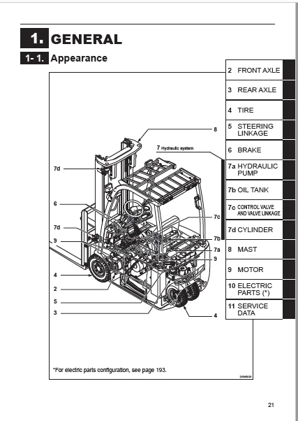
1 GENERAL 21
1-1 Appearance 21
1-2 Specifications 22
2 FRONT AXLE (DRIVE) 24
2-1 Names of parts 24
2-2 Disassembly and reassembly 25
2-2-1 Front tire – removal and installation 25
2-2-2 Front axle – removal 27
2-2-3 Front axle – installation 29
2-2-4 Front axle – disassembly 31
2-2-5 Front axle – reassembly 37
2-3 Inspection and adjustment 42
2-3-1 Gears – inspection 42
2-3-2 Bearings – inspection 42
2-3-3 Packing – inspection and replacement 42
2-3-4 Overall – inspection 42
2-3-5 Brake plates – inspection and replacement 43
2-4 Troubleshooting 44
2-4-1 Front axle – troubleshooting 44
3 REAR AXLE (STEERING) 45
3-1 Names of parts 45
3-2 Disassembly and reassembly 46
3-2-1 Rear tire – removal and installation 46
3-2-2 Rear axle – removal 48
3-2-3 Rear axle – installation 49
3-2-4 Rear axle – disassembly 50
3-2-5 Rear axle – reassembly 54
3-3 Inspection and adjustment 58
3-3-1 Steering angle potentiometer – adjustment 58
3-3-2 EPS torque sensor – adjustment 59
3-3-3 Minimum turning radius – measurement 63
3-4 Troubleshooting 64
3-4-1 Rear axle – troubleshooting 64
4 TIRE 65
4-1 Front tire 65
4-1-1 Names of parts 65
4-1-2 Front tire – specifications 66
4-1-3 Front tire – removal and installation 66
4-2 Rear tire 67
4-1-2 Names of parts 67
4-2-2 Rear tire – specifications 68
4-2-3 Rear tire – removal and installation 68
4-3 Inspection and adjustment 69
4-3-1 Hub nut – inspection 69
4-3-2 Air pressure – inspection 69
4-3-3 Tire – visual inspection and replacement 70
4-4 Troubleshooting 70
4-4-1 Tire – troubleshooting 70
5 STEERING LINKAGE 71
5-1 Names of parts 71
5-2 Disassembly and reassembly 73
5-2-1 Steering linkage – removal 73
5-2-2 Steering linkage – installation 77
5-3 Inspection and adjustment 78
5-3-1 Joint – inspection and replacement 78
5-3-2 Steering wheel – inspection and replacement 78
5-3-3 Roller chain Comp – adjustment 79
6 BRAKE 81
6-1 Names of parts 81
6-1-1 Foot brake linkage – names of parts 81
6-1-2 Parking brake linkage – names of parts 82
6-2 Disassembly and reassembly 83
6-2-1 Foot brake linkage – disassembly 83
6-2-2 Foot brake linkage – reassembly 85
6-2-3 Master cylinder – disassembly and reassembly 86
6-2-4 Wheel brake – disassembly and reassembly 87
6-2-5 Parking brake linkage – removal and installation 88
6-3 Inspection and adjustment 89
6-3-1 Wheel brake – inspection and adjustment 89
6-3-2 Master cylinder Ass’y – inspection and replacement 89
6-3-3 Brake circuit – air bleeding 91
6-3-4 Brake pedal – inspection 94
6-3-5 Brake pedal and bracket
– adjustment of clearance 94
6-3-6 Brake pedal height – adjustment 95
6-3-7 Foot brake microswitch – adjustment 96
6-3-8 Parking brake lever – inspection and adjustment 96
6-4 Troubleshooting 97
6-4-1 Wheel brake – troubleshooting 97
6-4-2 Parking brake – troubleshooting 98
7 HYDRAULIC SYSTEM 99
7-1 Hydraulic circuit 99
7-1-1 Hydraulic operating circuit 100
7-2 Hydraulic piping 102
7-2-1 Hydraulic line 102
7-2-2 Hydraulic piping – precautions for removing 104
7-2-3 Hydraulic piping – precautions for installing 105
7a HYDRAULIC PUMP 106
7a-1 Names of parts 106
7a-2 Disassembly and reassembly 107
7a-2-1 Hydraulic pump – removal and installation 107
7a-3 Inspection and adjustment 109
7a-3-1 Hydraulic pump – inspection 109
7a-4 Troubleshooting 110
7a-4-1 Hydraulic pump – troubleshooting 110
7b OIL TANK 111
7b-1 Disassembly and reassembly 111
7b-1-1 Oil tank – removal and installation 111
7b-1-2 Oil tank – disassembly and reassembly 112
7b-2 Inspection and adjustment 114
7b-2-1 Oil – inspection 114
7b-2-2 Recommended oil and Oil quantity 114
7b-2-3 Hydraulic oil – draining 116
7b-2-4 Oil tank and filters – cleaning and check 116
7b-3 Troubleshooting 116
7b-3-1 Oil tank – troubleshooting 116
7c CONTROL VALVE 117
7c-1 Control valve linkage 117
7c-2 Disassembly and reassembly 119
7c-2-1 Control valve – removal and installation 119
7c-2-2 Control valve relief pressure – identification 121
7c-3 Inspection and adjustment 122
7c-3-1 Relief pressure – measuring and adjustment 122
7c-3-2 Microswitch – adjustment 123
7c-3-3 Manually lowering lift in emergencies 124
7c-4 Troubleshooting 125
7c-4-1 Control valve – troubleshooting 125
7d CYLINDER 126
7d-1 Disassembly and reassembly 126
7d-1-1 Lift cylinder (Simplex/Triplex/Duplex mast) –
preparation for removing 126
7d-1-2 Lift cylinder (Simplex mast) – removal 127
7d-1-3 Lift cylinder (Triplex/Duplex mast) – removal 128
7d-1-4 Tilt cylinder – removal 130
7d-1-5 Lift cylinder – installation 131
7d-1-6 Tilt cylinder – installation 132
7d-1-7 Lift cylinder – disassembly 133
7d-1-8 Lift cylinder – reassembly 142
7d-1-9 Tilt cylinder – disassembly and reassembly 147
7d-2 Inspection and adjustment 150
7d-2-1 Cylinder Comp – inspection 150
7d-2-2 Piston rod – inspection 150
7d-2-3 Diagnosing oil leaks 151
7d-2-4 Vertical and tilt drift – inspection 152
7d-3 Troubleshooting 153
7d-3-1 Cylinder – troubleshooting 153
8 MAST 154
8-1 Names of parts 154
8-2 Disassembly and reassembly 157
8-2-1 Simplex mast – removal 157
8-2-2 Triplex/Duplex mast – removal 159
8-2-3 Mast – installation 162
8-2-4 Mast – disassembly and reassembly 163
8-3 Inspection and adjustment 166
8-3-1 Mast – inspection 166
8-3-2 Lift bracket – inspection 166
8-3-3 Back shoe – inspection 167
8-3-4 Chain wheel – inspection 167
8-3-5 Lift chain – inspection and replacement 168
8-3-6 Fork – inspection 169
8-3-7 Roller – inspection and adjustment 170
8-3-8 Clearance between Back shoe and Inner mast –
inspection and adjustment 172
8-3-9 Lift chain tension – inspection and adjustment 173
8-3-10 Mast leaning – adjustment 174
8-4 Troubleshooting 176
8-4-1 Mast · Lift bracket · Fork – troubleshooting 176
9 MOTOR 177
9-1 Names of parts 177
9-1-1 Traction motor – names of parts 177
9-1-2 Hydraulic motor – names of parts 178
9-1-3 EPS motor – names of parts 179
9-2 Disassembly and reassembly 180
9-2-1 Traction motor – removal and installation 180
9-2-2 Hydraulic motor – removal and installation 181
9-2-3 EPS motor – removal and installation 182
9-2-4 Traction motor – disassembly and reassembly 183
9-2-5 Hydraulic motor – disassembly and reassembly 184
9-2-6 EPS motor – disassembly and reassembly 185
9-3 Inspection and adjustment 186
9-3-1 Rotor SUB Ass’y (Traction and Hydraulic motor) –
inspection and replacement 186
9-3-2 Sensor bearing Comp (Traction motor) –
inspection and replacement 187
9-3-3 Stator Comp (Traction and Hydraulic motor) –
inspection and replacement 187
9-3-4 Motor Ass’y (Traction and Hydraulic motor) –
inspection 188
9-3-5 Armature Comp (EPS motor) – inspection and
replacement 190
9-3-6 Brush, Brush holder and Spring (EPS motor) –
inspection and replacement 192
9-4 Troubleshooting 194
9-4-1 Motor – troubleshooting 194
Caterpillar EP20TBCB(J) Controller Lift Truck Service Manual
1 Basic setting 1
1-1 Monitor display functions 1
1-1-1 Indicator panel 1
1-1-2 Indication of display 2
1-1-3 Display : functions 3
1-1-4 Mode selection 9
1-2 Control boards 16
1-2-1 Basic control board system layout 16
1-2-2 Travel/Hydraulic board (Printed board) 17
1-2-3 EPS controller 17
1-2-4 Rotary switch on the Travel/Hydraulic board 19
1-2-5 Rotary switch on the EPS controller 20
1-2-6 Adjustment Standards List for EP-TCB series 22
2 Settings and adjustments 23
2-1 Service setting check 23
2-2 Setting with the EPS controller and
the monitor display 25
2-2-1 Display monitor icon check and setting 25
2-2-2 Model setting 27
2-2-3 Switch back (plugging/regenerative) braking
force adjustment 28
2-2-4 Regenerative braking force check and
adjustment 29
2-2-5 Pitching control adjustment 30
2-2-6 Hydraulic speed setting and adjustment 31
2-2-7 Display language check and settings 35
2-2-8 Optional function check and settings 36
2-2-9 Lift interrupt function check 38
2-2-10 Current detector check 39
2-2-11 Accelerator potentiometer adjustment 44
2-2-12 Steering angle potentiometer adjustment 45
2-2-13 I/O Check 46
2-2-14 Error history memory1 55
2-2-15 Error history memory 2 57
2-2-16 Battery voltage calibration 58
2-2-17 Load sensor check and calibration 59
2-2-18 Electricity consumption meter check 61
2-2-19 Turning speed reduction setting and check
(OPTION) 64
2-2-20 Clearing the error history memory (memory
initialization) 65
3 Troubleshooting 66
3-1 Self diagnosis function 66
3-1-1 Display 66
3-1-2 Error message list 69
4 Other electrical system checks and adjustments 71
4-1-1 Chassis insulation check 71
4-1-2 Display brightness check and adjustment 71
4-1-3 Hour meter check 72
4-1-4 Auto-power-off function check 73
4-1-5 OIS (Operation Interlock System) check 73
4-1-6 Parking brake alert working check 75
4-1-7 Cooling fan check 77
4-1-8 Turn signal lamp check 77
4-1-9 Built-in charger check 78
4-1-10 Brake oil level warning check 79
4-1-11 Laser pointer check (OPTION) 79
4-1-12 Travel inhibitor check (OPTION) 79
4-1-13 Travel/hydraulic interlock check
(Battery side loading, OPTION) 80
4-1-14 Battery electrolyte level sensor check (OPTION) 80
5 Wiring (Diagrams) 81
5-1 Wiring, system 81
5-1-1 EP9TCB-20TBCB 81
5-1-2 EP9TCB-20TBCB (with two relays for backward) 82
5-2 Wiring, body 83
5-2-1 EP9TCB-20TBCB 83
5-2-2 EP9TCB-20TBCB (with two relays for backward) 84
5-3 Harness, body 85
5-3-1 EP9TCB-20TBCB 85
5-3-2 EP9TCB-20TBCB (with two relays for backward) 86
5-3-3 EP9TCB-20TBCB (with new EPS sensor/Midori Sokki) 87
5-4 Controller wiring 88
5-4-1 EP9TCB-20TBCB 88
5-5 Controller harness 89
5-5-1 Built-in charger/Stationary charger 89
5-5-2 CE specification 90
5-6 Main controller Ass’y 91
5-6-1 Built-in charger/Stationary charger 91
5-6-2 Built-in charger/Stationary charger 92
5-6-3 CE specification 93
5-6-4 CE specification 94
5-6-5 AS specification 95
5-7 Wiring, BC 96
5-7-1 3 phases 200/400V 96
5-8 Harness, BC 97
5-8-1 3 phases 200/400V 97
5-9 Wiring, lamp 99
5-9-1 Revolving lamp 99
5-9-2 Working lamp 100
5-9-3 Backup lamp 101
5-9-4 Rear lamp 102
5-9-5 Tilt level lamp, without laser pointer 103
5-9-6 Tilt level lamp, with laser pointer 104
5-10 Forward & backward chime/ buzzer 105
5-10-1 [Wiring, buzzer (forward & backward)] 105
5-10-2 [Wiring, chime (forward & backward)] 106
5-10-3 [Forward chime / backward buzzer] 107
5-10-4 [Wiring, chime (backward)] 108
5-11 Wiring, lift limit 109
5-12 Harness, accessory 110
5-13 Wiring, heater 111
5-14 Wiring, seat heater 112
5-15 Wiring, lift limit 113
5-16 Wiring, signal 114
5-17 Wiring, wiper 115
IMAGES PREVIEW OF THE MANUAL:
CATERPILLAR EP20TBCB(J) LIFT TRUCK SERVICE MANUAL – PDF DOWNLOAD:
PLEASE NOTE:
- This is the SAME exact manual used by your dealers to fix your vehicle.
- The same can be yours in the next 2-3 mins as you will be directed to the download page immediately after paying for the manual.
- Any queries / doubts regarding your purchase, please feel free to contact [email protected]
S.V