Trusted Business
Verified & Licensed
Virus Free Files
100% Safe Downloads
Secure Payment
SSL Protected
Instant Delivery
Available Immediately
Sale!


CATERPILLAR TH336 TH337 TH406 & TH407 Parts Manual – PDF DOWNLOAD 
CATERPILLAR TH336 TH337 TH406 & TH407 Parts Manual – PDF DOWNLOAD
CATERPILLAR TH336 TH337 TH406 & TH407 Parts Manual – PDF DOWNLOAD
Original price was: $70.00.$19.95Current price is: $19.95.
CATERPILLAR TH336 TH337 TH406 & TH407 Parts Manual – PDF DOWNLOAD
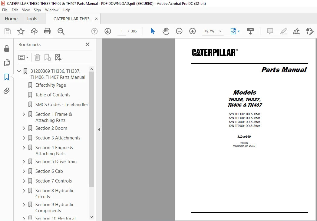
S/N TDE00100 & After
S/N TDF00100 & After
S/N TBX00100 & After
S/N TBY00100 & After
31200369
Instant PDF Download
Available immediately
Save to Your Device
Download & keep forever
Antivirus Scanned
100% virus-free
Trusted Worldwide
175,000+ customers
Description
CATERPILLAR TH336 TH337 TH406 & TH407 Parts Manual – PDF DOWNLOAD
TABLE OF CONTENTS:
CATERPILLAR TH336 TH337 TH406 & TH407 Parts Manual – PDF DOWNLOAD
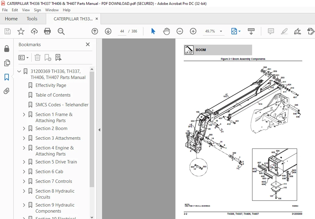
31200369 TH336, TH337, TH406, TH407 Parts Manual
.......................  1
	Effectivity Page
...................................................  3
	Table of Contents
..................................................  5
	SMCS Codes - Telehandler
...........................................  9
	Section 1 Frame & Attaching Parts................................... 15
		Figure 1-1 Frame Shrouding & Trim............................... 16
		Figure 1-2 Frame Shrouding & Trim - Engine Pod Installation..... 20
		Figure 1-3 Axle & Wheel Mounting................................ 22
		Figure 1-4 Retrieval Hitch...................................... 26
		Figure 1-5 Pin Hitch, Auto Hitch & Piton Frame-Auto Hitch....... 28
		Figure 1-6 Pin Hitch - Cuna C & Cuna D2......................... 32
		Figure 1-7 Hydraulic Hitch...................................... 36
		Figure 1-8 Fixed Position Hitch................................. 40
	Section 2 Boom...................................................... 43
		Figure 2-1 Boom Assembly Components............................. 44
		Figure 2-2 First Boom Section Assembly.......................... 48
		Figure 2-3 Second Boom Section.................................. 50
		Figure 2-4 Quick Coupler & Quick Disconnect Installation........ 52
		Figure 2-5 JD Coupler Installation.............................. 56
		Figure 2-6 Boom Prop Installation............................... 58
		Figure 2-7 JCB Coupler, Manual & Hydraulic...................... 60
		Figure 2-8 Manitou Coupler Installation, Manual & Hydraulic..... 64
	Section 3 Attachments............................................... 69
		Figure 3-1 Carriage Assembly.................................... 70
		Figure 3-2 Forks................................................ 72
		Figure 3-3 Side Shift Carriage.................................. 74
		Figure 3-4 Rotate/Side Tilt Carriage............................ 76
		Figure 3-5 General Purpose Bucket............................... 78
		Figure 3-6 Multi-Purpose Bucket................................. 80
		Figure 3-7 Material Handling Bucket............................. 82
		Figure 3-8 Grapple Bucket....................................... 84
		Figure 3-9 Truss Boom........................................... 86
		Figure 3-10 Lifting Hook........................................ 88
		Figure 3-11 50 in & 72 in Rotate/Side Tilt Carriage Assembly.... 90
		Figure 3-12 50 in & 72 in Carriage Assembly..................... 92
		Figure 3-13 100 Degree Swing Carriage........................... 94
	Section 4 Engine & Attaching Parts.................................. 97
		Figure 4-1 Engine & Transmission Installation................... 98
		Figure 4-2 CAT Engine...........................................104
		Figure 4-3 Fuel Line Installation...............................108
		Figure 4-4 Fuel Tank Installation...............................112
		Figure 4-5 Radiator Installation................................114
		Figure 4-6 Air Cleaner Installation.............................118
		Figure 4-7 Muffler Installation.................................122
		Figure 4-8 Block Heater Installation............................124
		Figure 4-9 Reversing Fan - Hydraulic............................126
		Figure 4-10 Reversing Fan - Pneumatic...........................130
	Section 5 Drive Train...............................................133
		Figure 5-1 Front Axle Assembly..................................134
		Figure 5-2 Front Axle - Axle Housing............................136
		Figure 5-3 Front Axle - Swivel Housing & Steering Cylinder......138
		Figure 5-4 Front Axle - Bevel Gear Set..........................140
		Figure 5-5 Front Axle - Differential............................142
		Figure 5-6 Front Axle - Double U-Joint..........................144
		Figure 5-7 Front Axle - Brakes..................................146
		Figure 5-8 Front Axle - Wheel Hub...............................148
		Figure 5-9 Front Axle - Final Reduction.........................150
		Figure 5-10 Front Axle - Brake Caliper..........................152
		Figure 5-11 Rear Axle Assembly..................................154
		Figure 5-12 Rear Axle - Axle Housing............................156
		Figure 5-13 Rear Axle - Swivel Housing & Steering Cylinder......158
		Figure 5-14 Rear Axle - Bevel Gear Set..........................160
		Figure 5-15 Rear Axle - Differential............................162
		Figure 5-16 Rear Axle - Double U-Joint..........................164
		Figure 5-17 Rear Axle - Wheel Hub...............................166
		Figure 5-18 Rear Axle - Final Reduction.........................168
		Figure 5-19 Drive Shaft Installation............................170
		Figure 5-20 Remote Grease System Installation...................172
		Figure 5-21 Tire & Wheel Installation...........................174
	Section 6 Cab.......................................................179
		Figure 6-1 Cab Installation.....................................180
		Figure 6-2 Cab Assembly.........................................192
		Figure 6-3 Open Cab Interior Installation.......................198
		Figure 6-4 Enclosed Cab Interior Installation...................200
		Figure 6-5 Cab Door & Window Installation.......................202
		Figure 6-6 Wiper System.........................................206
		Figure 6-7 Cab Covers & Cab Guards..............................208
		Figure 6-8 Vinyl Mechanical Suspension Seat.....................210
		Figure 6-9 Cloth Mechanical Suspension Seats....................212
		Figure 6-10 Cloth Pneumatic Suspension Seats....................214
		Figure 6-11 Cab Heater/AC Components............................216
		Figure 6-12 Engine Heater/AC Components.........................220
		Figure 6-13 Heater/AC Unit & Heater/AC Unit Guard Shield........224
	Section 7 Controls..................................................227
		Figure 7-1 Joystick.............................................228
		Figure 7-2 Steering Column......................................230
		Figure 7-3 Accelerator Pedal....................................232
		Figure 7-4 Mechanical Handbrake.................................234
		Figure 7-5 Brake Installation...................................236
	Section 8 Hydraulic Circuits........................................239
		Figure 8-1 Supply Circuit.......................................240
		Figure 8-2 Dump Circuit.........................................244
		Figure 8-3 Steer Select Valve...................................248
		Figure 8-4 Service Brake........................................250
		Figure 8-5 Lift Cylinder........................................252
		Figure 8-6 Extend/Retract.......................................258
		Figure 8-7 Tilt & Tilt Compensating Cylinder....................260
		Figure 8-8 Auxiliary Hydraulics.................................262
		Figure 8-9 Rear Auxiliary Hydraulics w/Trailer Brakes...........264
	Section 9 Hydraulic Components......................................269
		Figure 9-1 Lift Cylinder........................................270
		Figure 9-2 Extend/Retract Cylinder..............................272
		Figure 9-3 Tilt Cylinder........................................274
		Figure 9-4 Compensation Cylinder................................276
		Figure 9-5 Quick Coupler Cylinder...............................278
		Figure 9-6 Main Control Valve...................................280
		Figure 9-7 Piston Pump..........................................284
		Figure 9-8 Steering Select Valve................................286
		Figure 9-9 Hydraulic Tank Installation..........................288
		Figure 9-10 Diverter Valve......................................290
		Figure 9-11 Combination Valve...................................294
		Figure 9-12 Swing Carriage Cylinder.............................296
	Section 10 Electrical...............................................299
		Figure 10-1 Engine & Transmission Electronic Installation.......300
		Figure 10-2 Cab Electronic Installation.........................304
		Figure 10-3 Cab Switches........................................308
		Figure 10-4 Boom & Frame Electronic Installation................310
		Figure 10-5 Worklight & License Plate Light Installations.......314
		Figure 10-6 Driving Light Installation..........................318
		Figure 10-7 Engine Harness......................................322
		Figure 10-8 Cab Floor Harness...................................328
		Figure 10-9 Cab Roof Harness....................................338
		Figure 10-10 Transmission Harness...............................340
		Figure 10-11 Front Frame Harness................................342
		Figure 10-12 Rear Frame Harness.................................344
		Figure 10-13 Boom Harness.......................................350
		Figure 10-14 Boom Worklight Harness & Headlight Harness.........352
		Figure 10-15 Tow Hitch Harness..................................354
		Figure 10-16 Boom Suspension Cab Components.....................356
	Section 11 Decals...................................................361
		Figure 11-1 Cab & Frame Decals..................................362
		Figure 11-2 Boom Decals.........................................368
	Maintenance parts list..............................................371
	Part Number Index...................................................373
IMAGES PREVIEW OF THE MANUAL:


PLEASE NOTE:
- This is the SAME manual used by the dealers to troubleshoot any faults in your vehicle. This can be yours in 2 minutes after the payment is made.
- Contact us at [email protected] should you have any queries before your purchase or that you need any other service / repair / parts operators manual.
S.M