
CAV DPC Fuel Injection Pump Workshop Manual Pub C2135 1981 PDF Download
Original price was: $24.95.$14.95Current price is: $14.95.
Complete workshop manual for the CAV DPC rotary distributor fuel injection pump. Covers principles of operation, transfer pressure regulation, metering and distribution, excess fuel delivery for starting, mechanical governor, automatic advance, special systems and specifications for high-speed diesel engines up to 2 litres.
Description
File Details
- Manual Type: Workshop Manual
- Brand: CAV
- Model: DPC Fuel Injection Pump
- Language: English
- Page Count: 133
- File Format: PDF
- Publication Number: C2135(En)
- Year: 1981
- Publisher: CAV Parts and Service / Service Publications Department
About the DPC Pump
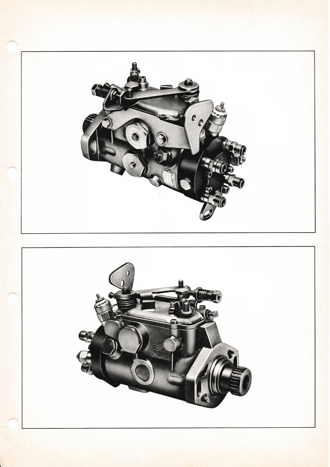
The CAV DPC is a compact rotary distributor type fuel injection pump designed for high-speed diesel engines with cubic capacities up to 2 litres. It forms a sealed assembly that requires no external lubrication system and is lubricated entirely by the filtered fuel with which it is filled during operation. Internal pressure keeps dust, water and contaminants out while specially designed circuits prevent air accumulation.
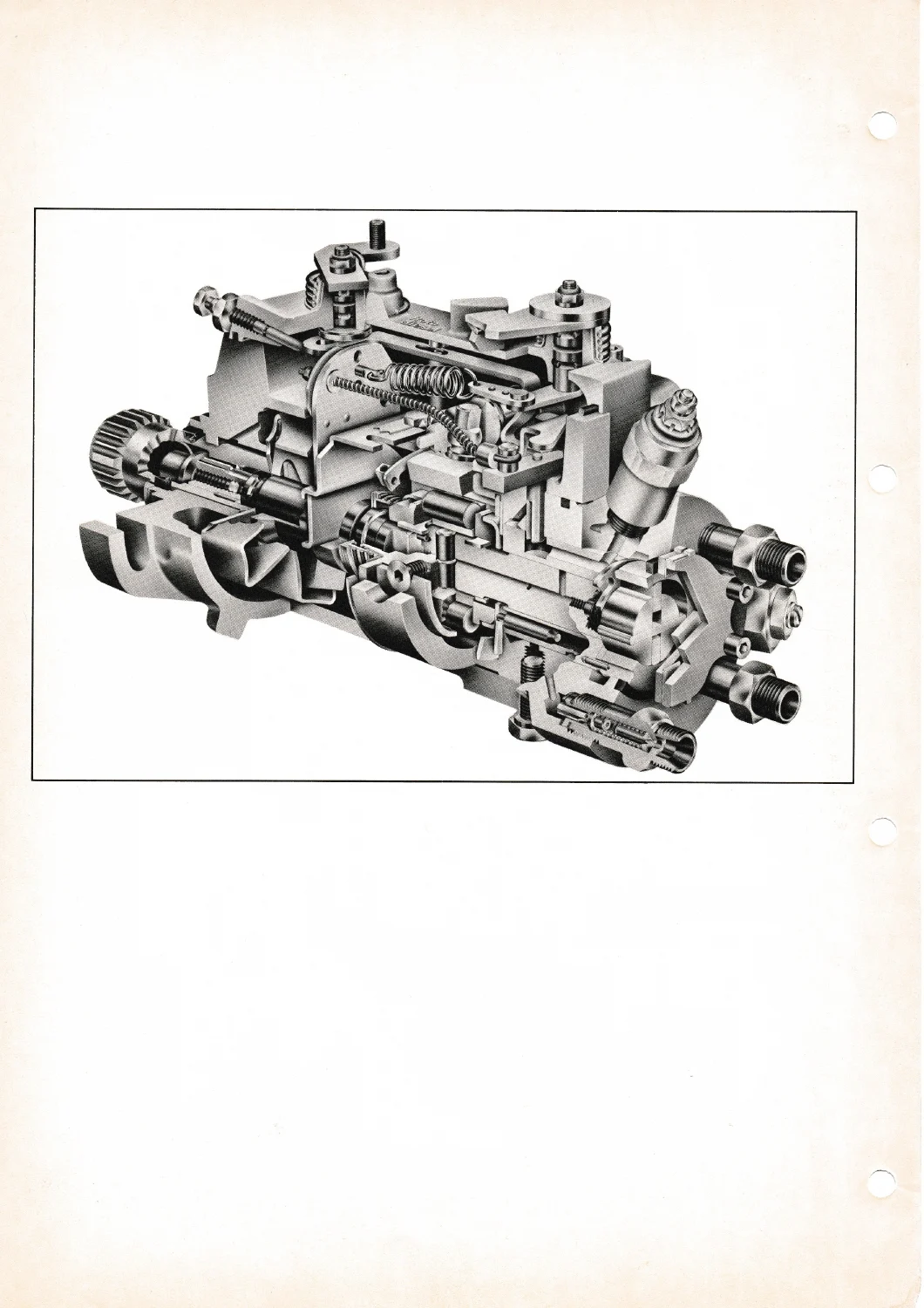
A single pumping element consisting of two opposed plungers is built into the pump rotor. The rotor turns inside a fixed hydraulic head. Each plunger contacts the internal lobes of a cam ring through roller and shoe assemblies. Fuel is accurately metered as it enters the pumping element and is then distributed to the injectors in the correct firing order at the precise moment required.
Chapters Covered
- Preface – General, Specifications and Description of the DPC Pump, Despatch Number Significance, Fuel Circuit and Principle of Operation, Injection Cycle
- Transfer Pressure – Transfer Pump, Regulating Valve, Distribution Ring
- Pumping, Metering and Distribution – Principle of Operating, Pumping and Distribution, Metering, Hydraulic Head, Maximum Fuel Delivery
- Excess Fuel Delivery – Principle of Operation, Shoe and Roller Assembly Movements, Excess Delivery Valve, Excess Fuel Delivery Position, Normal Delivery Position
- Governor – All Speed Mechanical Governor, Principle of Operation of the Mechanical Governor
- Adjustment of Commencement of Ignition – Automatic Start-Retard Speed Advance (Description and Principle of Operation)
- Drive – Description
- Special Systems – Anti Stall Device, Venting (Metering Valve Vent, Venting Jet, Excess Fuel Delivery Valve Venting), High Pressure Delivery Valves, Solenoid Shut-off Valve, Increased Idling Speed Device, Advance Override, Notched Belt Drive, Low Load Advance, Mini-Maxi Governor
- Specifications
- Dismantling and Reassembly procedures for standard and variant drive arrangements
Taken together the manual provides a complete understanding of how the DPC pump meters, pressurises and distributes fuel, how the mechanical governor maintains speed under varying load, how the automatic excess fuel system assists cold starting, and how the hydraulic advance unit varies injection timing with engine speed. It also covers the various special systems that may be fitted according to engine application.
Key Operating Principles
Filtered fuel enters through a banjo bolt fitted with a fine mesh filter and is raised to transfer pressure by a positive-displacement transfer pump. A regulating valve maintains transfer pressure in relation to pump speed. Fuel at transfer pressure reaches the metering valve, whose orifice area is controlled by the centrifugal governor. The resulting metered pressure fills the pumping element through ports in the hydraulic head and rotor.
During the intake phase a distributor rotor inlet port aligns with a metering port so that fuel pushes the opposed plungers outward. As the rotor turns the inlet is sealed and a distributor port aligns with an outlet; at the same time the rollers contact opposite cam lobes and force the plungers inward, generating the high pressure that opens the injector.
An automatic excess-fuel system increases delivery at low speeds by axially shifting the shoe and roller assemblies so that the plungers travel further. Once transfer pressure rises the excess-fuel valve opens and the shoes return to the normal full-load position. A differential valve controlled by transfer pressure determines whether the pump is in excess or normal delivery.
Governor and Timing Systems
The all-speed mechanical governor uses centrifugal weights that move the metering valve to maintain the selected engine speed regardless of load. The automatic start-retard and speed-advance unit is actuated by transfer pressure and alters the angular position of the cam ring, thereby changing the commencement of injection according to engine speed.
Additional devices covered include the solenoid shut-off valve for remote engine stop, the anti-stall device, increased-idling-speed control for cold operation, low-load advance, advance override and the mini-maxi two-speed governor arrangement.
Specifications Summary
- Number of outlets: 2, 3, 4 or 6
- Weight: 5.7 kg
- Injection order: depending on engine
- Mounting: flange on the pump casing secured by two CHC screws
- Drive: splined hub or gear wheel (notched-belt variants also covered)
- Governor: mechanical, all-speed
- Fuel: diesel oil
- Lubrication: fuel-oil lubricated
- Special systems: automatic excess fuel for starting, automatic start-retard and speed advance, engine shut-off by built-in solenoid valve
- Mounting position: any
Service Information
The manual includes detailed dismantling sequences for the standard pump with all-speed mechanical governor as well as provisional instructions for variants fitted with speed-controlled automatic advance and manual override, notched-belt drive, low-load advance and the mini-maxi governor. Reassembly notes stress the use of correct special tools and the matching of the distributor rotor to the hydraulic head bore, which must be treated as a single assembly.
Why This Manual Matters
Accurate fuel metering and precise injection timing are essential to the reliable operation of any diesel engine. The DPC pump is a self-contained rotary unit whose internal clearances, roller-shoe geometry, transfer-pressure regulation and governor calibration must be maintained to the original design intent. This workshop manual supplies the operating theory, component identification, adjustment procedures and dismantling guidance needed to diagnose faults, restore correct delivery and timing, and return the pump to service without guesswork.
Download the PDF instantly after payment. No shipping, readable on any device and ready to print for workshop use.
Reviews
There are no reviews yet.