
Cessna 182S 182T T182T Wiring Diagram Manual (1997 and On)
Original price was: $44.95.$26.95Current price is: $26.95.
Cessna 182S, 182T and T182T wiring diagram manual for airplanes 18280001 and on and T18208001 and on. It has circuit diagrams for power, avionics, lighting and engine indication, plus parts lists, indexes and wire repair practices. Instant PDF download.
Description
Cessna 182S 182T T182T Wiring Diagram Manual (1997 and On)
This Cessna 182S 182T T182T Wiring Diagram Manual covers the wiring of Model 182S and 182T airplanes from serial 18280001 on, and Model T182T airplanes from serial T18208001 on. Cessna Aircraft Company prepared it to help maintenance personnel locate, trace and repair aircraft wiring and electrical and electronic components. It follows Air Transport Association Specification 100 numbering, so its chapters line up with the Maintenance Manual and Illustrated Parts Catalog for the same airplane.
File Details
- Manual type: Wiring Diagram Manual
- Document title: Cessna Aircraft Company Model 182/T182 Wiring Diagram Manual
- Models covered: 182S, 182T and T182T
- Effectivity: Models 182S and 182T, airplanes 18280001 and ON; Model T182T, airplanes T18208001 and ON
- Revision level: Revision 4, 13 February 2006 (original issue 3 February 1997)
- Language: English
- File format: PDF
Chapters Covered in the Cessna 182S/182T Wiring Diagram Manual
- Chapter 20 – Standard Practices, Airframe: electrical safety precautions, wiring maintenance practices, bonding and grounding, soldering, electrical connectors, coax cable connectors, splices and terminals, heat shrink tubing, resistors, torque values for threaded fasteners, sealing of electrical connectors
- Chapter 21 – Air Conditioning: avionics cooling fan
- Chapter 22 – Auto Flight: roll servo actuator, wing leveler, single axis autopilot, dual axis autopilot (NAV I, NAV I with HSI, NAV II and NAV III versions)
- Chapter 23 – Communications: GDL-69A data link provisions and FIS data link, audio system (standard, NAV I, NAV II, NAV III and GDL-69A FIS versions)
- Chapter 24 – Electrical Power: alternator system, 95 amp alternator option, battery system, switch panel assembly, power interface, power converter, circuit breaker panel, split avionics master option, avionics circuit breaker panels
- Chapter 25 – Equipment/Furnishings: emergency locator transmitter, Pointer ELT
- Chapter 27 – Flight Controls: control wheels, flap control
- Chapter 28 – Fuel: fuel quantity
- Chapter 30 – Ice and Rain Protection: pitot heater and heated stall warning, propeller deice
- Chapter 31 – Indicating/Recording Systems: clock, OAT and hourmeter, annunciator panel, CO Guardian detector, PFD and MFD displays
- Chapter 33 – Lights: instrument dimming, flight and engine instrument lighting, dimming control module, map lights, interior lights, glareshield lighting, oxygen lighting, navigation lights, strobe lights, flashing beacon, under wing courtesy lights, landing and taxi lights
- Chapter 34 – Navigation: air data and AHRS, KMD-540 multifunction display, KCS-55A HSI, flux detector, turn coordinator, Garmin magnetometer, Stormscope and WX-500, KTA-870 traffic advisory, KMH-880 provisions, KX-155A NAV/COMM #1 and #2, KN-63 DME, KLN-89, KLN-89B and KLN-94 GPS, KR-87 ADF, KT-76A and KT-76C transponders, GTX33 transponder, Garmin integrated avionics system
- Chapter 37 – Vacuum: vacuum out warning
- Chapter 73 – Engine Fuel and Control: fuel pump
- Chapter 74 – Ignition: magneto system
- Chapter 77 – Engine Indicating: EGT/CHT, TIT/CHT, manifold pressure and fuel flow, engine/airframe monitor
- Chapter 79 – Oil: oil temperature and oil pressure
- Chapter 80 – Starting: starting circuit, cross-referenced to Chapter 24
- Chapter 91 – Charts: connectors and ground locations
Taken together, the Cessna 182/T182 wiring diagrams follow every electrical and avionics system in the airplane, from the alternator, battery and circuit breaker panels to the lights, engine instruments and radios. Each diagram comes with its own parts list, so you can go from a wire on the page to the connector, contact, switch or component behind it.
How the Wiring Diagrams Are Organized
Every diagram carries a chapter-section-subject-figure number, which is how the Alphabetical Index and the parts indexes point you to the right sheet. Wires are identified by a number-letter code printed, stenciled or banded on each wire segment. That code tells you where the wire is used, and the manual explains how to read it. Components carry a reference designator of two letters and three numbers. The first letter gives the component type (splice, connector, relay, switch, light, circuit breaker and so on) and the second gives its general area of the airplane. The designator links the diagram to the parts list, where you find the part number, vendor code and effectivity.
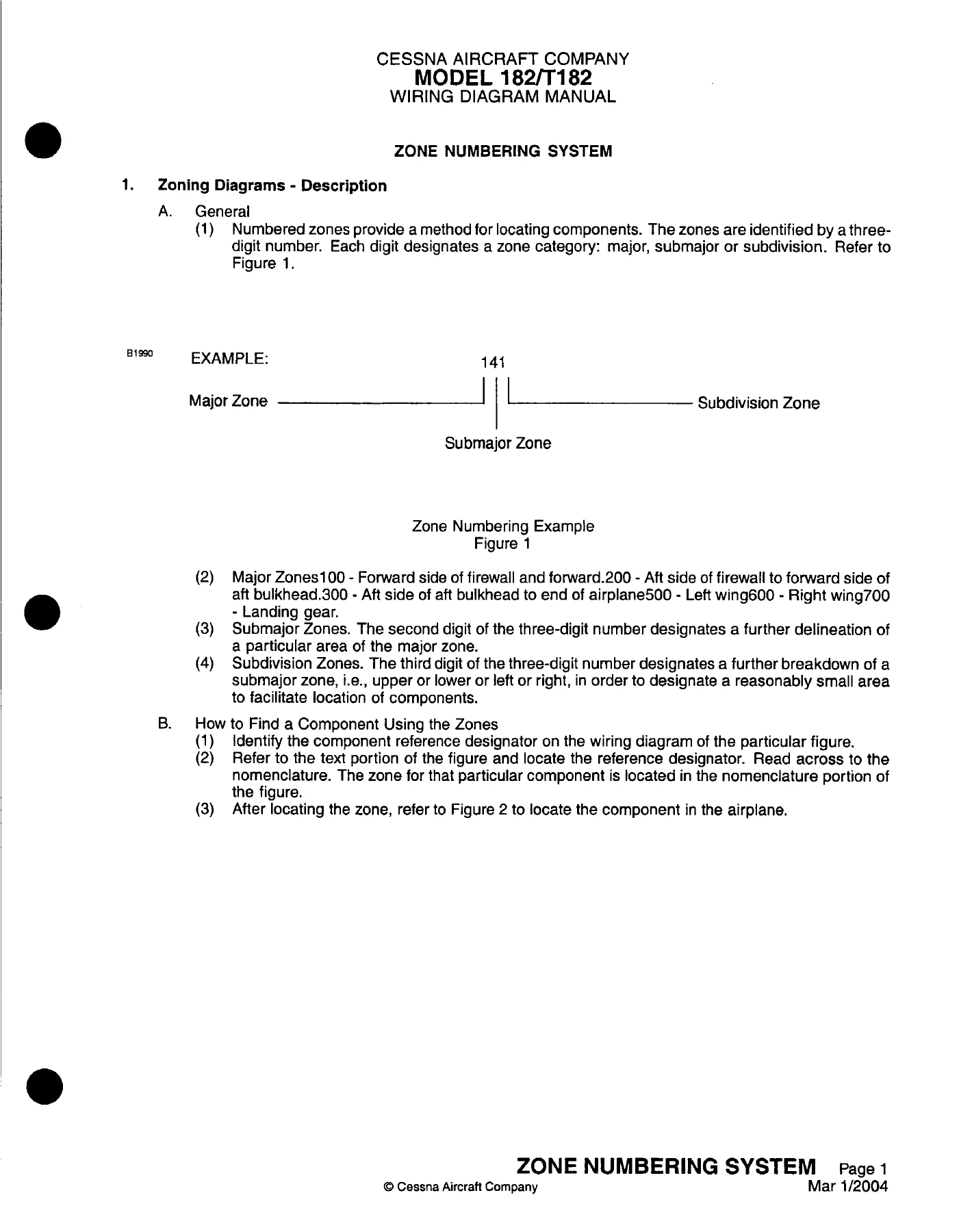
Locating a part is straightforward. Find its designator on the diagram, read across to the nomenclature line for its zone number, then use the Zone Numbering System to place it in the airplane. That system runs from 100 for forward of the firewall, through 200 (firewall to aft bulkhead) and 300 (aft of the aft bulkhead), to 500 for the left wing, 600 for the right wing and 700 for the landing gear. Relays and switches are drawn with the airplane on the ground and all circuits off or de-energized. A page of electrical symbols is included so you can read each diagram correctly.
Avionics Configurations and Serial Effectivity
The 182S, 182T and T182T were built with more than one avionics package, and this manual keeps them separate. Diagrams are marked Standard, NAV I, NAV II or NAV III, and several carry HSI or ADF variants. Parts lists show which airplanes each entry applies to with a ten-character effectivity code. In the abbreviated columns, 80001 stands for airplane 18280001 and 8001 stands for T18208001. For that reason, the effectivity block at the top of each parts list matters when a diagram appears on more than one sheet.
Wire Repair and Electrical Practices (Chapter 20)
Chapter 20 is a practical reference for the shop. It covers wire types and specifications, wire identification and reidentification, installation and routing rules, wire stripping limits for nicked strands, splicing of ordinary and shielded wire, and when coax may or may not be spliced. It also has tables of crimp-type and solder-type connector contacts with their insertion, extraction and crimp tools. Those tables cover MS3106, Molex, AMP Mate-N-Lock, Deutsch, LMD4000, M24308 D-subminiature and RE/RM series connectors. Further sections cover shield termination with solder sleeves and band clamps (with resistance limits), soldering practice, splices and terminals, heat shrink tubing, resistor codes, torque values for current-carrying and ground fasteners, and sealing of connectors.
Reference Tables, Indexes and Parts Data
Front-matter tables give quick answers without opening a single diagram:
- Light Bulb Replacement Guide with reference designators, zones, quantities and bulb part numbers
- Fuse Replacement Guide for the MC01-2 Power Distribution Box
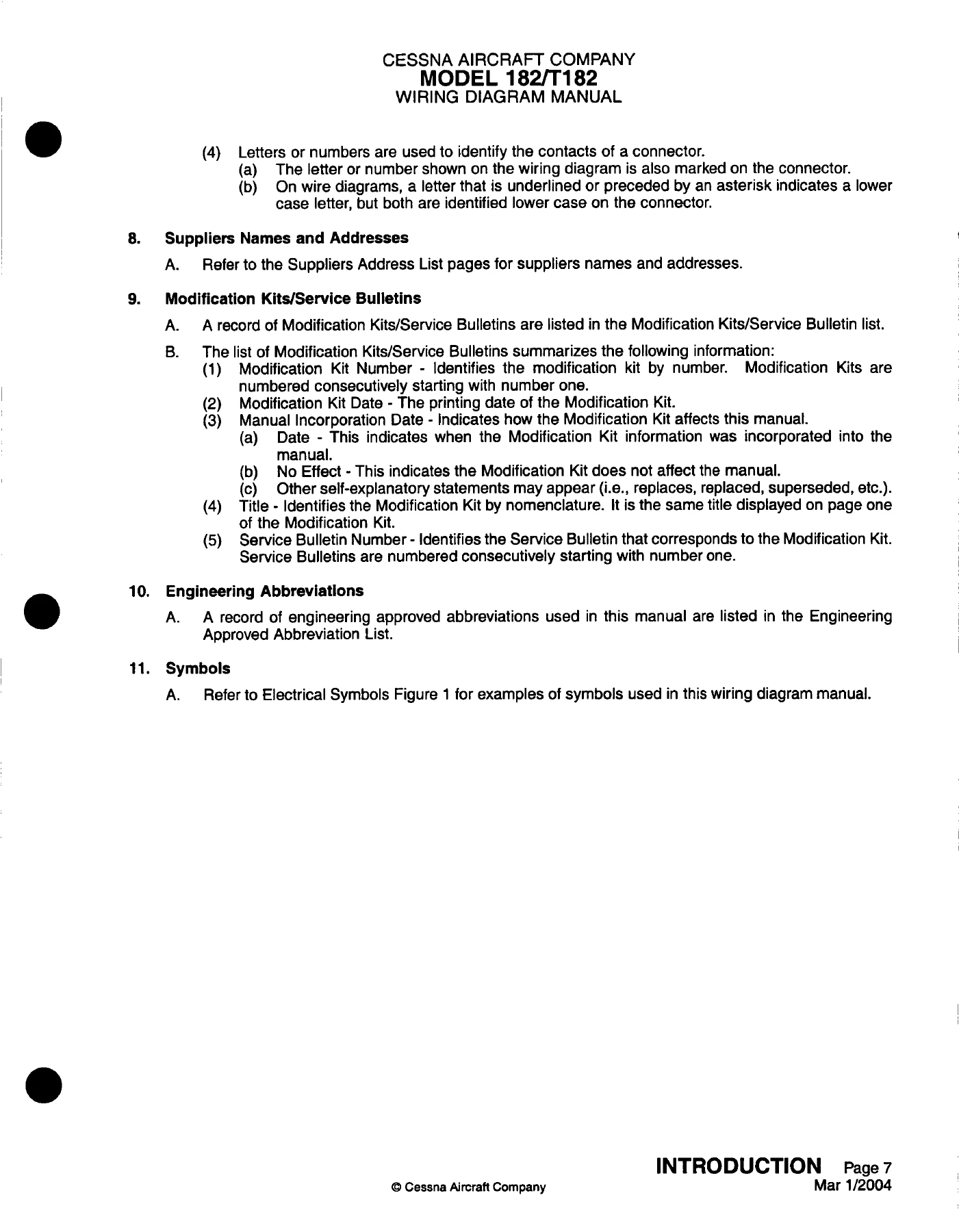
- Service Bulletin List with bulletin numbers, titles, dates and how each affects the manual
- Supplier Address List keyed to vendor codes in the parts lists
- Engineering Approved Abbreviations
IMAGES PREVIEW
Four back-of-front-matter indexes let you enter the manual from whatever you already know:
- Alphabetical Index by system name
- Component Index with the location of each component
- Reference Designator Index
- Part Number Index
Chapter 91 adds connector charts and ground location charts for circuits that share connectors and grounds.
Scope Note
This Cessna 182S 182T T182T Wiring Diagram Manual is a reference for locating, tracing and repairing wiring and for identifying replacement components. It does not include inspection, maintenance or parts requirements for Supplemental Type Certificate (STC) installations, so any STC equipment fitted to your airplane needs the STC holder’s own data.
What This Manual Lets You Do
With this Cessna 182S 182T T182T wiring diagram manual you can trace a circuit from the breaker to the load and check continuity against the printed wire numbers. You can pin out a connector, find out where a ground lands, identify a part number before you order it, and repair or replace wire to the stated standards. Working from the correct diagram for your serial number and avionics package lets you troubleshoot avionics and electrical faults without guessing at which version of a circuit is in your airplane. You receive the manual as an instant PDF download with no shipping. It opens on any phone, tablet or computer, and you can print the diagram pages you need for the hangar floor.
Reviews
There are no reviews yet.