Challenger 9800 VE Planter 9816 VE 9824 VE Operator’s Manual 700745956B – PDF DOWNLOAD
Original price was: $89.95.$25.95Current price is: $25.95.
Challenger 9800 VE Planter 9816 VE 9824 VE Operator’s Manual 700745956B – PDF DOWNLOAD
Description
Challenger 9800 VE Planter 9816 VE 9824 VE Operator’s Manual 700745956B – PDF DOWNLOAD
CHALLENGER 9800 VE PLANTER 9816 VE 9824 VE OPERATOR’S MANUAL 700745956B – PDF DOWNLOAD:
IMAGES PREVIEW OF THE MANUAL:


DESCRIPTION:
Challlenger 9800 VE Planter 9816 VE 9824 VE Operator’s Manual 700745956B – PDF DOWNLOAD
A word to the operator :
It is your responsibility to read and understand the safety section in this manual and the manual for all attachments before operating this machine. Remember you are the key to safety. Good safety practices not only protect you, but also the people around you. Study the content in this manual and make the content a working part of your safety program.
- Keep in mind that this safety section is written only for this type of machine. Practice all other usual and customary safe working precautions, and above all remember – safety is your responsibility. You can prevent serious injury or death. This safety section is intended to point out some of the basic safety situations that may be encountered during the normal operation and maintenance of your machine.
- This section also suggests possible ways of dealing with these situations. This section is not a replacement for other safety practices featured in other sections of this manual. Personal injury or death may result if these precautions are not followed. Learn how to operate the machine and how to use the controls properly.
- Do not let anyone operate the machine without instruction and training. For your personal safety and the personal safety of others, follow all safety precautions and instructions found in the manuals and on safety signs affixed to the machine and all attachments. Use only approved attachments and equipment.
This manual:
This manual covers general safety practices for this machine. The operator manual must always be kept with the machine. Right-hand and left-hand, as used in this manual, are determined by facing the direction the machine will travel when in use. The photos, illustrations, and data used in this manual were current at the time of printing, but due to possible in-line production changes, your machine can vary slightly in detail. The manufacturer reserves the right to redesign and change the machine as necessary without notification.
TABLE OF CONTENTS:
Challenger 9800 VE Planter 9816 VE 9824 VE Operator’s Manual 700745956B – PDF DOWNLOAD
1 Safety 9
1 1 Introduction 11
1 1 1 Safety alert symbol 1 1
1 1 2 Safety messages 1 1
1 1 3 Informational messages 1 1
1 1 4 Safety signs 1 1
1 1 5 A word to the operator 1 2
1 1 6 This manual 13
1 2 Operation 14
1 2 1 Prepare for operation 1 4
1 2 2 General information 1 4
1 2 3 Personal protective equipment 1 5
1 2 4 Seat instructions 1 5
1 2 5 Shield and guards 1 6
1 2 6 Exhaust warning 1 6
1 2 7 Flying debris 17
1 2 8 Handrails 17
1 2 9 Agricultural chemicals 17
1 3 Travel on public roads 18
1 4 Maintenance 20
1 4 1 General maintenance information 20
1 4 2 Fire prevention and first aid 2 1
1 4 3 High pressure leaks 2 2
1 4 4 Tire safety 23
1 4 5 Replacement parts 23
1 4 6 D-ring 2 4
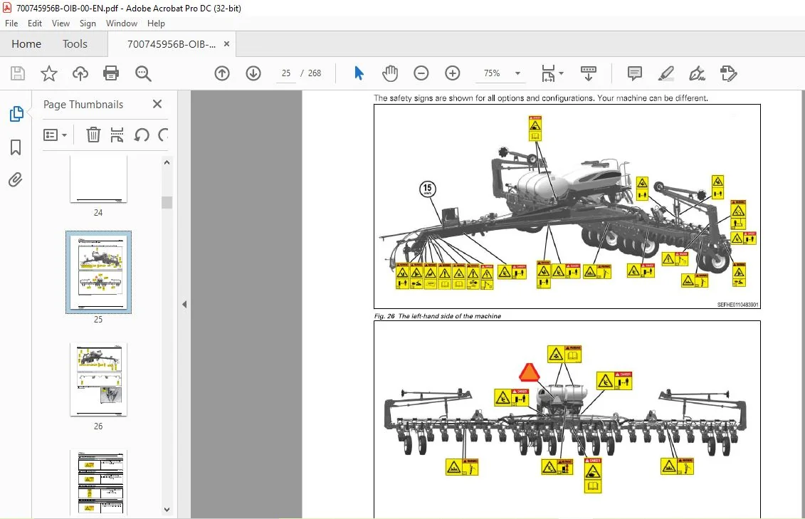
1 5 Safety and informational signs 25
1 5 20 Slow Moving Vehicle (SMV) sign 3 1
1 5 2 1 Reflector location 3 2
1 6 Cylinder stops 33
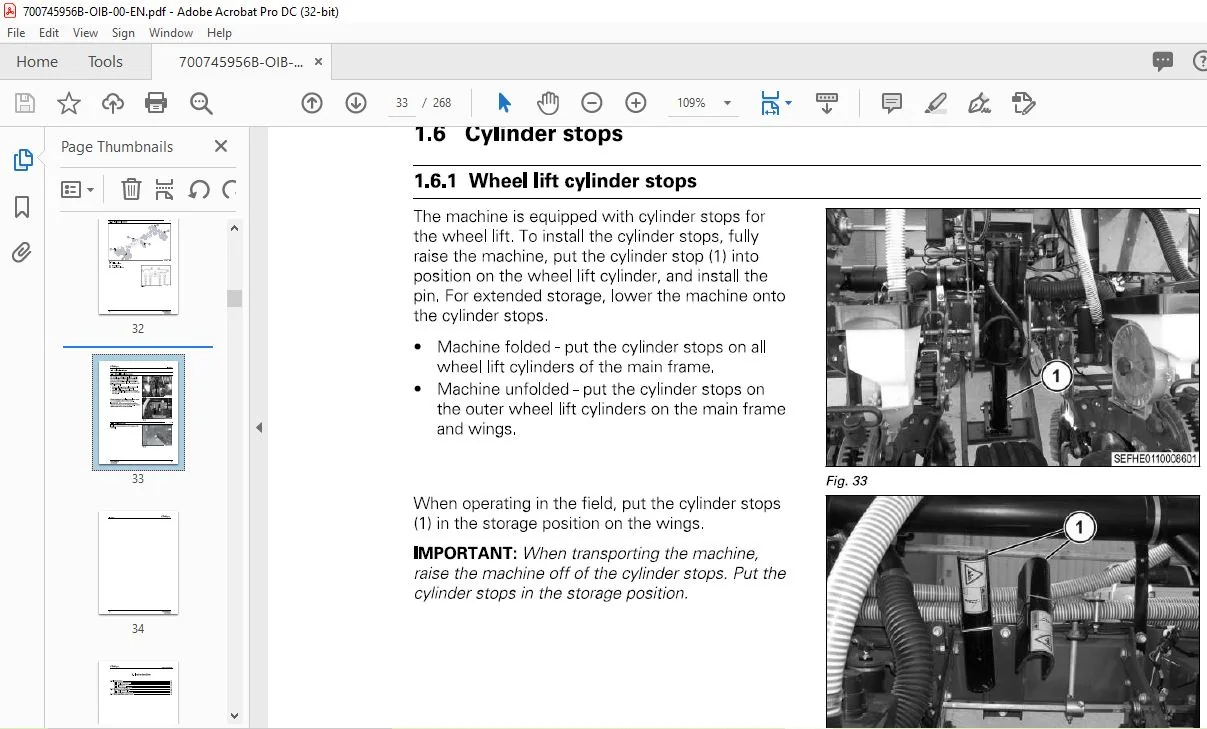
1 6 1 Wheel lift cylinder stops 33
1 6 2 Transport pins 33
2 Introduction 35
2 1 Introduction 37
2 1 1 Units of measurement 37
2 1 2 Replacement parts 37
2 1 3 Intended use 37
2 1 4 Proper disposal of waste 37
2 2 Machine identification 38
2 2 1 Serial number plate 38
2 2 2 Serial number description 38
2 3 Main machine components 40
3 Operation 41
3 1 Connecting the planter to the tractor 45
3 1 1 Preparing the tractor 4 5
3 1 2 Connecting the 3-point linkage 4 5
3 1 3 Connecting the drawbar hitch 47
3 1 4 Connecting the hydraulic hoses 47
9800 VE Planter
7007459568
Table of contents
3 1 5 Adjusting the remote valve flow 48
3 1 6 Installing the hydraulic pump, if equipped 48
3 1 7 Hitch height 49
3 1 7 1 Setting the 3-point linkage height 49
3 1 7 2 Setting the drawbar hitch height 5 0
3 2 Disconnecting the planter from the tractor 51
3 3 Preparing the machine for operation 53
3 4 Frame control box operation 54
3 5 Folding and unfolding the planter 55
3 5 1 Folding the machine 5 5
3 5 2 Unfolding the machine 5 7
3 6 Roading the machine 60
3 6 1 Preparing to road the machine 6 0
3 6 2 Safety precautions 6 0
3 6 3 Lamp operation 6 0
3 7 Field operation 62
3 7 1 Operating in the field 6 2
3 7 2 Checking the seed population 6 3
3 7 3 Finishing the field 6 3
3 8 Seed 65
3 8 1 Seed lubricant 6 5
3 9 Seed meter 66
3 9 1 Seed meter components 6 6
3 9 2 Crop kits 6 7
3 9 2 1 Crop setup guide 6 7
3 9 2 2 Replacing a crop kit 7 1
3 9 3 Checking the disc shims 7 6
3 9 4 Removing a seed meter 8 0
3 9 5 Installing a seed meter 8 1
3 9 6 Assembling the hopper 8 3
3 10 SpeedTube TM
85
3 10 1 Yearly maintenance 8 5
3 10 2 SpeedTube TM crop change 8 5
3 10 3 Change from SpeedTube TM to seed tube 8 5
3 10 4 SpeedTubeTM inspection 8 6
3 10 5 Replace the belt 9 1
3 11 Seed meter vacuum 94
3 1 1 1 Vacuum settings 9 4
3 1 1 2 Vacuum motor operation 9 4
3 12 Central fill air pressure 95
3 1 2 1 Adjusting the central fill air pressure 9 5
3 13 Seed removal 96
3 1 3 1 Removing seed from the central fill system 9 6
3 14 Row units 98
3 14 1 Gauge wheels 9 8
3 14 2 Adjusting the seed depth 9 8
3 14 3 Checking the seed depth 9 8
3 15 Closing wheels 100
3 15 1 Dual wheel down pressure 10 1
3 15 2 Single wheel down pressure 10 1
3 15 3 Closing wheel spacing and offset 10 1
3 15 3 1 Adjusting the closing wheel spacing and offset 102
3 15 4 Centering the closing wheels 10 2
3 16 Markers 103
3 16 1 Marker operation 103
9800 VE Planter
7007459568
Table of contents
3 16 2 Marker shear bolt 103
3 16 3 Adjusting the marker disc 104
3 16 4 Adjusting the marker arm length 104
3 1 6 4 1 Marker arm length 105
3 17 Liquid fertilizer 106
3 17 1 Filling the liquid fertilizer tank 106
3 17 2 Checking the fertilizer application rate 107
3 17 3 Cleaning the strainer screen 107
3 17 4 Preparing for night storage 107
3 17 5 Preparing for one to two week storage – permitted method 108
3 17 6 Preparing for one to two week storage – better method 108
3 17 7 Preparing for winter storage 109
3 18 Liquid fertilizer pumps 110
3 18 1 Piston pump 1 10
3 18 1 1 Piston pump rate chart 1 10
3 18 1 2 Piston pump slide chart 1 1 1
3 18 1 3 Setting the piston pump 1 1 2
3 18 1 4 Starting the pump 1 1 2
3 18 1 5 Checking the tire pressure 1 1 2
3 18 1 6 Adjusting the down pressure of the fertilizer transmission 1 1 3
3 18 2 Centrifugal pump 1 1 3
3 18 2 1 Priming the centrifugal pump 1 1 3
3 19 Liquid fertilizer distribution 114
3 19 1 Flow divider 1 14
3 19 2 Boom distribution 1 14
3 19 2 1 Changing the orifices 1 14
3 19 2 2 Nozzle orifice chart 1 15
3 20 Liquid fertilizer openers 118
3 20 1 Fertilizer opener adjustments 1 18
3 20 2 Adjusting the double disc opener 1 18
3 20 3 Adjusting the single disc opener depth 1 1 9
3 20 4 Adjusting the fertilizer opener spacing 1 1 9
3 20 5 Adjusting the single opener disc swivel 1 20
3 20 6 Adjusting the single spring tension 1 20
3 21 ISOBus fertilizer electronics 122
3 21 1 Software icon descriptions 1 22
3 21 2 Symbol icons 1 26
3 21 2 1 Accumulator data 1 27
3 21 3 Main work screen 1 27
3 21 3 1 Configuring the main work screen 1 28
3 21 3 2 Work screen data 1 28
3 21 4 Terminal information 1 3 5
3 21 5 Master switch 1 3 5
3 21 5 1 External master switch 1 3 6
3 21 5 2 Terminal master switch 1 3 6
3 21 6 Implement lift switch, if equipped 1 3 6
3 21 6 1 Enabling the implement lift switch 1 3 7
3 21 6 2 Adjusting the master switch timeout 1 3 7
3 21 7 Transferring data 1 3 8
3 21 8 Module information screen 1 3 9
3 21 9 Hydraulic/electric fertilizer pump setup example 1 3 9
9800 VE Planter
7007459568
3 21 9 1 Setting the product 1 3 9
3 21 9 2 Liquid flow calibration 140
3 21 9 3 Configuring the channel setup – liquid flow 14 1
3 21 9 4 Calibrating the channel – liquid flow 14 1
3 21 9 5 Doing the 100% catch test 14 3
3 21 9 6 Doing the partial catch test 144
Table of contents
3 21 9 7 Doing the nozzle flow meter test 144
3 21 10 Planter setup 144
3 21 10 1 Configuring the channel setup – liquid flow 145
3 21 10 2 Activating more than one channel 146
3 21 10 3 Calibrating the channel valve 146
3 21 10 4 Configuring the speed setup 147
3 21 10 5 Configuring the speed source 147
3 21 10 6 Linking channels 148
3 21 10 7 Configuring the physical layout 148
3 21 1 1 Changing a product setting 149
3 21 1 2 Product setup screen – preset method enabled 15 0
3 21 1 3 Product setup screen – preset method disabled 15 1
3 21 14 Ground speed setup 15 2
3 21 14 1 Configuring the speed source 15 5
3 21 15 Module configuration 15 6
3 21 1 6 Diagnostics 15 7
3 21 17 Alarms 15 9
3 21 17 1 Alarm history 15 9
3 21 17 2 Alarm detail 1 6 0
3 21 17 3 Clearing the alarm history 1 6 0
3 21 17 4 Alarm list 1 6 0
3 21 18 Accumulator screen 17 0
4 Maintenance 173
4 1 Service schedule 175
4 2 Checklists 176
4 2 1 Beginning of the day 17 6
4 2 2 End of the day 17 6
4 2 3 Beginning of the season 17 6
4 2 4 Storage 17 6
4 3 Lubrication points 178
4 3 1 Sealed bearings 17 8
4 3 2 Row unit lubrication points 17 8
4 3 3 Frame lubrication points 17 9
4 3 4 Tongue lubrication points 18 0
4 3 5 3-point linkage lubrication points 18 1
4 3 6 Drawbar hitch lubrication points 18 2
4 3 7 Marker lubrication points 18 2
4 3 8 Wheel pivot lubrication points 18 4
4 3 9 Fertilizer piston pump 18 4
4 3 9 1 Single piston pump lubrication 18 4
4 3 9 2 Double piston pump lubrication 18 5
4 4 Seed meter 186
4 4 1 Yearly maintenance 18 6
4 4 2 Checking the disc shims 18 6
4 4 3 Replacing the vacuum seal 1 9 0
4 5 Hydraulic 191
4 5 1 Changing the hydraulic oil and filter 19 1
4 5 2 Cleaning the hydraulic oil coolers 19 2
4 6 Wheel bearings 193
4 6 1 Lubricating the wheel bearings 19 3
4 6 2 Replacing the wheel bearings 19 3
4 6 3 Adjusting the wheel bearings 1 9 5
4 7 Row unit 197
4 7 1 Adjusting the gauge wheel to opener clearance 1 9 7
4 7 2 Calibrating the gauge wheel depth 1 9 7
4 7 3 Removing the gauge wheels 1 9 8
9800 VE Planter
7007459568
Table of contents
4 7 4 Installing the gauge wheels 1 9 8
4 7 5 Replacing the opener disc bearings 1 9 9
4 7 6 Replacing the opener discs 200
4 7 7 Setting the opener disc contact 202
4 7 8 Removing the seed tubes 203
4 7 9 Installing the seed tubes 204
4 7 1 0 Replacing the tube guard 204
4 7 1 1 Adjusting the tube clip 204
4 8 Seed sensors 206
4 8 1 Cleaning the seed sensors 206
4 8 2 Testing the seed sensors 206
4 8 3 Replacing the seed sensors 207
4 9 Switches 208
4 9 1 Frame height limit switch 208
4 9 1 1 Adjusting the frame height limit switch 208
4 9 2 Marker positon switch 209
4 10 Electronic controls 21 o
4 1 0 1 General electronic maintenance 21 0
4 1 0 2 Electrical system overview 21 1
4 1 0 3 Status lamp for the single row module and vDrive module 21 4
5 Troubleshooting 215
5 1 Low vacuum 217
5 2 vSet troubleshooting 218
5 3 Hydraulic troubleshooting 220
5 4 Planter troubleshooting 222
5 5 Single disc fertilizer opener troubleshooting 226
5 6 Liquid fertilizer pumps 228
5 6 1 Centrifugal pump troubleshooting 228
5 6 2 Electric pump troubleshooting 228
6 Specifications 231
6 1 Specifications 233
6 1 1 Frame specifications 233
6 1 2 Tire specifications 233
6 1 3 Machine dimensions 234
6 1 4 Marker specifications 234
6 1 5 Row unit specifications 234
6 1 6 Hydraulic system specifications 235
6 1 7 Shear pin specifications 235
6 1 8 Approximate shipping weight 235
6 1 9 Special bolt torques 235
6 1 1 0 Tractor requirement 236
7 Accessories 239
7 1 Accessories 241
7 1 1 Stroke control segments kit 24 1
7 1 2 Closing wheel kits 24 1
7 1 2 1 Single rubber wheel 24 1
7 1 2 2 Angled dual rubber wheels 24 1
7 1 2 3 Angled dual cast iron wheels 24 2
7 1 3 Attachments mounted on the row unit linkage 24 2
9800 VE Planter
7007459568
7 1 3 1 Disc furrower attachment 24 2
7 1 3 2 Bed leveler 24 2
7 1 3 3 Spring tines 24 3
7 1 3 4 Adjusting the row unit linkage attachments 24 3
Table of contents
7 1 4 Row unit mounted tillage 244
7 1 4 1 Row unit-mounted tillage coulter 244
7 1 4 2 Coulter with residue manager 244
7 1 4 3 Residue manager 244
7 1 4 4 Trashmaster attachment 245
7 1 4 5 Floating residue manager 245
7 1 5 Frame mounted tillage 245
7 1 5 1 Frame-mounted tillage coulter 245
7 1 5 2 Coulter with residue manager 246
7 1 5 3 Strip/ridge till discs 246
7 1 5 4 Stabilizing coulter 246
7 1 6 Coulter disc blades 246
7 1 7 Liquid fertilizer kit 248
7 1 8 Fertilizer Openers Kit 249
7 1 8 1 Double-disc fertilizer opener 249
7 1 8 2 Single-disc fertilizer opener 249
7 1 9 Tow hitch kit 249
7 1 10 Drive wheel mud scraper kit 25 0
7 1 1 1 Gauge wheel mud scraper kit 25 0
7 1 1 2 Weight kit 25 0
7 1 1 3 Marker kit 25 1
7 1 14 Safety and instructional sign replacement 25 1
8 Assembly 253
8 1 Assembly safety 255
8 2 Assembling the machine 256
8 2 1 Priming the hydraulic circuits 25 6
8 2 2 Removing the cover from the SMV emblem 25 7
8 2 3 Radar 25 8
8 2 4 Assembling the hydraulic pump 25 8
8 2 5 Filling the hydraulic tank 25 9
8 3 Checklists 260
8 3 1 Pre-delivery checklist 26 0
8 3 2 Delivery checklist 26 0
9 Index 261
9800
PLEASE NOTE:
- This is the same manual used by the dealers to diagnose and troubleshoot your vehicle
- You will be directed to the download page as soon as the purchase is completed. The whole payment and downloading process will take anywhere between 2-5 minutes
- Need any other service / repair / parts manual, please feel free to contact [email protected] . We still have 50,000 manuals unlisted
S.V