Challenger EU Applicators TerraGator TG8400C Flotation Chassis Workshop Service Manual 79037161C
Original price was: $89.95.$30.95Current price is: $30.95.
Challenger EU Applicators TerraGator TG8400C Flotation Chassis Workshop Service Manual 79037161C – PDF DOWNLOAD
Description
Challenger EU Applicators TerraGator TG8400C Flotation Chassis Workshop Service Manual 79037161C – PDF DOWNLOAD
IMAGES PREVIEW OF THE MANUAL:


FILE DETAILS:
Challenger EU Applicators TerraGator TG8400C Flotation Chassis Workshop Service Manual 79037161C – PDF DOWNLOAD
Size: 233 MB
Format: PDF
Language: English
Brand: Challenger
Type of Machine: Applicators
Type of document: Workshop Service Manual
Model: Challenger EU Applicators TerraGator TG8400C Flotation Chassis
Number of Pages: 1378 pages
Date Modified: 09/2019
Part Number: 79037161C
DESCRIPTION:
Challenger EU Applicators TerraGator TG8400C Flotation Chassis Workshop Service Manual 79037161C – PDF DOWNLOAD
Service manual
1.1.1 Units of measurement
Measurements are given in metric units followed by the equivalent in US units. Hardware sizes are given in millimeters for metric hardware and inches for US hardware.
1.1.2 Replacement parts
To receive your parts quickly, have the following information:
Correct part description and part number
Model number of the machine
Serial number of the machine
1.1.3 Product identification information
Each machine has an identification plate with the model number and the serial number.
The product identification number (Pl N) identifies a
machine for an operator to ride.
The manufacturers plate contains the PIN.
The serial numbers identify the engines,
transmissions, and attachments.
For reference, record the PIN on the line provided below:
The manufacturer’s plate (1) is on the right side of frame weldment.
TABLE OF CONTENTS:
Challenger EU Applicators TerraGator TG8400C Flotation Chassis Workshop Service Manual 79037161C – PDF DOWNLOAD
General 1-1
11 Service manual1-3
111 Units of measurement 1-3
112 Replacement parts 1-3
113 Product identification information1-3
114 Transmission serial number plate 1-3
115 Serial number definition1-4
116 Engine serial number plate 1-4
12 Important safety information 1-5
121 Prepare for operation 1-5
122 Fire prevention and first aid 1-6
123 Safety symbol 1-7
124 Safety messages1-7
125 Information messages 1-7
126 General hazard information 1-8
12 7 Pressurized air 1-9
128 Asbestos information 1-9
129 Electrical storm injury prevention 1-9
1210 Mount and dismount the machine1-9
1211 Before starting the engine 1-9
1212 Start the engine 1-10
1213 Before operating the machine 1-10
1214 Operate the machine 1-10
1215 Park the machine1-11
1216 Operator station1-12
1217 Cut and crush prevention 1-12
1218 Boom safety 1-12
1219 Fuel safety 1-12
1220 Hydraulic safety 1-13
1221 Chemical safety 1-13
1222 Exit the cab in an emergency 1-15
1223 Engine safety 1-15
1224 Safety lamps and marking devices use1-17
1225 Operating on slopes 1-17
1226 Roading on public roads 1-17
1227 Avoid eye contact with radar1-18
1228 Exhaust fumes 1-18
1229 Electrical power lines overhead 1-18
1230 Shield and guards 1-19
1231 Towing 1-19
1232 Modifications 1-20
1233 A word to the operator 1-20
1234 Work in a clean area 1-21
1235 Support the machine correctly 1-21
1236 Maintenance safety 1-21
1237 High pressure leaks1-25
13 Lubrication and maintenance 1-27
131 Maintenance introduction 1-27
132 Maintenance symbols1-27
133 Maintenance chart 1-28
134 Daily maintenance schedule 1-29
135 Maintenance schedule 10 to 1000 hours 1-29
Maintenance Schedule 2000 to 4000 hours1-32
Lubricants and fluids 1-32
Lubricant filling reminders 1-34
2 Engine, fuel, and exhaust system 2-1
21 Engine system 2-9
211 Remove the serpentine belt2-9
212 Install the serpentine belt 2-9
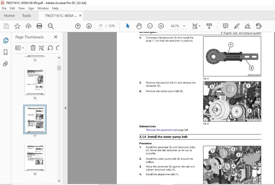
213 Remove the water pump belt 2-10
214 Install the water pump belt 2-11
215 Remove the alternator 2-12
216 Install the alternator 2-13
217 Remove the cooling package2-14
218 Install the cooling package 2-21
219 Remove the radiator core 2-27
2110 Install the radiator core 2-29
2111 Remove the hydraulic cooler and transmission cooler 2-31
2112 Install the hydraulic cooler and transmission cooler 2-33
2113 Remove the air intake assembly 2-35
2114 Install the air intake assembly 2-38
2115 Remove the air cleaner filter 2-41
2116 Install the air cleaner filter 2-42
2117 Remove the fan2-42
2118 Install the fan 2-46
2119 Remove the air compressor 2-49
2120 Install the air compressor 2-53
2121 Remove the starter 2-55
2122 Install the starter 2-56
2123 Remove the engine 2-57
2124 Install the engine 2-62
22 Safety instructions 2-68
23 To the user 2-70
231 Engine type designations 2-71
232 Location of the engine serial number 2-72
233 Type plate of the electronic control unit 2-73
234 Lift the engine 2-73
24 Engine construction2-75
241 Technical data 2-75
2411 Principal dimensions and data 2-75
2412 Fuel system 2-75
2413 Lubrication system 2-75
2414 Cooling system 2-75
2415 Selective Catalyst Reduction (SCR) system technical data 2-76
Cylinder block 2-77
Flywheel housing 2-77
Valve mechanism 2-77
Cylinder head 2-78
Crank mechanism 2-78
Timing gears 2-79
Lubrication system 2-80
2481 Oil pressure regulating valve 2-81
2482 Oil filter and oil cooler 2-81
Cooling system 2-81
2491 Thermostat 2-82
2410 Air control system2-83
24101 2 stage turbocharging 2-84
24102 Interstage charge air cooling 2-84
Applicator Chassis
79037161C
Table of contents
24103 Throttle valve 2-84
2411 Fuel system 2-85
2412 SCR system 2-86
24121 Selective Catalyst Reduction (SCR) system overview2-86
24122 Selective Catalyst Reduction (SCR) system components and their
functions2-87
24123 Supply module connectors and filters 2-88
24124 Dosing module connections 2-89
2413 Engine control system 2-89
25 Technical data 2-91
251 Cylinder block 2-91
252 Cylinder liners 2-91
253 Cylinder head 2-92
254 Valves and rockers 2-93
255 Tappets and push rods 2-94
256 Camshaft 2-94
257 Crankshaft2-94
258 Flywheel 2-96
259 Timing gears 2-96
2510 Connecting rod 2-97
2511 Piston, rings and pin 2-97
2512 Lubrication system 2-98
2513 Oil pump 2-99
2514 Thermostat 2-99
2515 Turbocharger 2-99
26 Tightening torques 2-100
27 Special tools 2-102
271 Cylinder block tools 2-102
272 Timing gear and flywheel housing tools 2-104
273 Cylinder head and valve mechanism tools2-105
274 Crank mechanism tools 2-108
275 Coolant pump tools 2-109
276 Air control system tools 2-110
2 77 Fuel system tools 2-111
278 SCR system tools2-115
2 79 Electronic diagnostic tool 2-116
2791 EDT diagnostic terminal 2-117
2792 Diagnostic terminal components 2-117
28 Liquid quality requirements2-119
281 Lubricating oil quality requirements 2-119
282 Coolant quality requirements 2-119
283 Fuel quality requirements 2-120
2831 Biodiesel blends2-121
2832 Engine output depending on fuel quality 2-123
29 Terminal diagram2-124
210 Cylinder block 2-128
2101 Measure the cylinder liner wear 2-128
2102 Remove the cylinder liner2-128
2103 Do a check for the cyl inder block 2-128
2104 Change the camshaft bushing 2-129
2105 Fitting plug at camshaft rear end 2-130
2106 Oversize bushings for camshaft2-130
2107 Fitting plug at camshaft rear end (oversize bushings) 2-131
2108 Install the cylinder liner 2-131
2109 Remove the block heater 2-134
21010 Install the block heater 2-134
211 Flywheel housing 2-135
Applicator Chassis
79037161C
Table of contents
2111 Remove the flywheel housing 2-135
2112 Install the flywheel housing 2-135
2113 Changing crankshaft rear oil seal 2-136
212 Cylinder head 2-137
2121 Removing cylinder head 2-137
2122 Removing valves 2-137
2123 Do a check for the cylinder head 2-137
2124 Replace the valve guides 2-139
2125 Machine the valve seat 2-139
2126 Replace the valve seat rings2-139
2127 Grinding valves 2-140
2128 Fittingvalves2-141
2129 Install the cylinder head 2-141
213 Valve mechanism with hydraulic lash adjustment 2-143
2131 Engine with hydraulic lash adjusters 2-143
2132 How to recognize an engine with hydraulic lash adjusters 2-143
2133 Remove the valve cover 2-144
2134 Install the valve cover 2-144
2135 Pre-adjustment of the hydraulic lash adjusters 2-144
2136 Recondition the valve mechanism 2-145
2137 Assembling the valve mechanism with the hydraulic lash adjusters 2-146
2138 Pre-adjusting the hydraulic lash adjusters 2-147
2139 Replace the camshaft or the camshaft gear 2-150
214 Crankshaft 2-152
2141 Removing the crankshaft 2-152
2142 Checking crankshaft2-152
2143 Replace the crankshaft gears 2-153
2144 Installing the crankshaft 2-153
2145 Crankshaft hub piece 2-154
2146 Viscose type vibration damper 2-155
215 Connecting rods and pistons 2-156
2151 Removing pistons together with connecting rods 2-156
2152 Changing connecting rod bearings 2-156
21521 Piston pin bushing2-156
21522 Big-end bearing 2-157
2153 Do a check for the connecting rod 2-158
2154 Replace the piston rings 2-158
2155 Checking pistons 2-159
2156 Install the piston pin 2-160
2157 Install the piston together with the connecting rod 2-160
216 Flywheel 2-161
2161 Changing starter ring gear on flywheel 2-161
2162 Remove the flywheel 2-161
2163 Fitting flywheel2-161
217 Timing gear assembly 2-162
2171 Removing timing gear casing 2-162
2172 Install the timing gear housing2-163
2173 Power take-off 2-165
2174 Fan drive device 2-166
218 Lubrication system2-167
2181 Oil pressure regulating valve 2-167
2182 Remove the oil sump 2-167
2183 Remove the suction pipe of the oil pump 2-167
2184 Install the suction pipe of the oil pump 2-168
2185 Removing and dismantling lubricating oil pump 2-169
2186 Assembling and fitting lubricating oil pump2-169
2187 Install the oil sump gasket2-170
Applicator Chassis
79037161C
219
220
221
2188
2189
21810
21811
21812
21813
21814
21815
21816
Table of contents
21871 Install the oil sump gasket, metal gasket 2-170
21872 Install the oil sump gasket, paper gasket 2-170
21873 Install the oil sump gasket, cork gasket 2-171
Install the oil sump, self-carrying oil sump and cast oil sump 2-171
Install the oil sump, stamped steel oil sump 2-173
Piston cooling nozzles 2-173
Removing the oil cooler 2-174
Fitting the oil cooler 2-175
Remove the oil filter adapter2-175
Install the oil filter adapter2-176
Oil sump capacity 2-176
Closed crankcase ventilation2-176
218161 Remove the closed crankcase ventilation system components 2-176
218162 Installing the closed crankcase ventilation system components 2-177
Cooling system 2-178
2191 Remove the distribution pipe of the coolant 2-178
2192 Install the distribution pipe of the coolant 2-178
2193 Removing the thermostat 2-178
2194 Testing the thermostat 2-179
2195 Replace the thermostat 2-179
2196 Remove the coolant pump and the thermostat housing2-179
2197 Install the coolant pump and the thermostat housing 2-179
2198 Reconditioning coolant pump 2-180
21981 Coolant pumps with standard bearings 2-180
21982 Coolant pumps with heavy duty bearings 2-183
2199 Installing the cylinder head connection part 2-183
21910 Remove the idler pulleys, the belt tightener and the belt pulley 2-184
21911 Install the idler pulleys, the belt tightener and the belt pulley 2-185
Air control system maintenance 2-186
2201 Checking the air cleaner2-186
2202 Do a check for the inlet and exhaust pipes2-186
2203 Remove the actuator of the turbocharger 2-187
2204 Install the actuator of the turbocharger 2-187
2205 Remove the exhaust manifold and the turbochargers 2-187
2206 Removing the turbocharger 2-188
220 7 Checking the turbocharger2-189
2208 Install the high-pressure turbocharger 2-190
2209 Install the exhaust manifold and the turbochargers 2-190
22010 Remove the ICAC 2-191
22011 Install the ICAC 2-192
22012 Remove the intake manifold 2-192
22013 Install the intake manifold 2-193
Fuel system 2-194
2211 Bleed the fuel system 2-194
2212 Measuring fuel feed pressure 2-195
2213 Remove the fuel filters 2-195
2214 Install the fuel filters2-196
2215 Remove the injector overflow pipe 2-196
2216 Install the injector overflow pipe 2-196
2217 Inspecting injectors 2-197
22171 Remove the injectors (CRIN3) 2-197
22172 Install the injectors (CRIN3)2-199
2218 High-pressure pump2-201
22181 Remove the high-pressure pump 2-201
22182 Install the high-pressure pump 2-202
2219 Rail 2-202
22191 Removing the rail 2-203
22192 Install the rail2-204
Applicator Chassis
79037161C
Table of contents
22193 Removing the pressure control valve 2-204
22194 Fitting the pressure control valve 2-205
22195 Removing the pressure sensor 2-205
22196 Fitting the pressure sensor 2-205
22110 Troubleshooting of the Common rail fuel system 2-205
221101 Testing the suction pressure between the fuel tank and the fuel prefilter
2-205
221102 Testing the suction pressure between the fuel pre-filter and the feed
pump 2-207
221103 Testing the feed pressure between the feed pump and the fuel main
filter 2-209
221104 Testing the feed pressure between the main fuel filter and the highpressure
pump 2-210
221105 Testing the total return quantity from the injectors 2-211
221106 Testing the return quantity from the injectors 2-213
221107 Testing the pressure control valve leakage2-218
221108 Testing the pressure release valve leakage 2-220
221109 Testing the return line pressure 2-223
222 SCR system 2-224
2221 Selective Catalyst Reduction (SCR) system maintenance 2-224
2222 Mounting of SCR system components 2-225
2223 Removing the supply module 2-226
2224 Installing the supply module 2-226
2225 Removing the hydraulic connectors 2-226
2226 Installing the hydraulic connectors 2-226
2227 Replace the main filter and the inlet filter of the supply module 2-227
2228 SPN 521008 FMI 1 2-228
22281 Solve the DEF pressure build-up failure 2-229
22282 Supply module lifting capacity test 2-231
22283 Solve the failure when the SM lifting capacity test is not OK 2-232
22284 Solving the failure when the SM lifting capacity test is OK 2-234
2229 SPN 521025 FMI 31, SPN 521026 FMI 31 2-235
22291 Cleanup of the SCR catalyst 2-237
22292 Make the dosing rate test 2-238
22293 Checking the quality of DEF 2-242
223 Engine control system 2-244
2231 Remove the bracket of the electronic control unit 2-244
2232 Install the bracket of the electronic control unit 2-244
2233 Remove the electronic control unit 2-244
2234 Install the electronic control unit 2-244
2235 Replace the electronic control unit 2-245
2236 Replace an empty electronic control unit (ECU) 2-246
2237 Wiring sets2-247
22371 Injector wiring sets2-247
22372 Sensor and actuator wiring sets 2-248
22373 Wiring set for intake air heater 2-248
22374 Sensors of the engine control system 2-249
2238 Remove the wiring harnesses 2-252
2239 Install the wiring harnesses 2-253
224 Prepare the long block replacement2-254
225 Parts for the long block replacement2-255
2251 Delivery content of the long block engine 2-255
2252 The parts that must be removed from the old engine 2-255
2253 Other parts of the long block replacement2-256
226 Remove the engine 2-257
227 Lift the engine 2-258
2271 Lift the engine 2-258
Table of contents
Disassemble the engine 2-260
2281 Remove the wiring harnesses 2-260
2282 Remove the electronic control unit 2-260
2283 Remove the bracket of the electronic control unit 2-261
2284 Remove the exhaust manifold and the turbochargers 2-261
2285 Removing the EGR system 2-262
2286 Change oil filter 2-262
2287 Removing the oil cooler 2-262
2288 Remove the oil filter adapter 2-263
2289 Remove the ICAC 2-263
22810 Remove the distribution pipe of the coolant 2-264
22811 Remove the fuel filters 2-265
22812 Remove the closed crankcase ventilation system components 2-265
22813 Removing the rail 2-265
22814 Remove the high-pressure pump 2-266
22815 Remove the block heater 2-266
22816 Remove the intake manifold 2-266
22817 Remove the coolant pump and the thermostat housing 2-267
22818 Remove the idler pulleys, the belt tightener and the belt pulley 2-267
22819 Remove the valve cover 2-268
22820 Remove the injectors (CRIN3) 2-268
228201 Remove the injector overflow pipe 2-270
22821 Remove the flywheel 2-270
22822 Remove the oil sump 2-270
22823 Remove the suction pipe of the oil pump 2-271
22824 Remove the flywheel housing 2-271
Assemble the engine 2-272
2291 Prepare the new long block 2-272
2292 Install the flywheel housing 2-272
2293 Changing crankshaft rear oil seal 2-273
2294 Install the suction pipe of the oil pump 2-274
2295 Install the oil sump gasket2-275
22951 Install the oil sump gasket, metal gasket2-275
22952 Install the oil sump gasket, paper gasket2-275
22953 Install the oil sump gasket, cork gasket 2-275
Install the oil sump, self-carrying oil sump and cast oil sump 2-276
Install the oil sump, stamped steel oil sump 2-277
Fitting flywheel2-278
Install the high-pressure pump 2-278
Install the rail 2-279
Installing the closed crankcase ventilation system components 2-279
Install the fuel filters2-280
229121 Install the injector overflow pipe 2-280
Install the injectors (CRIN3) 2-281
Install the valve cover 2-282
Install the idler pulleys, the belt tightener and the belt pulley 2-282
Install the intake manifold2-282
Install the coolant pump and the thermostat housing2-283
Install the block heater2-283
Install the distribution pipe of the coolant 2-284
Install the ICAC 2-284
Install the oil filter adapter2-285
Fitting the oil cooler 2-285
Change oil filter 2-285
Fitting the EGR system 2-286
Install the exhaust manifold and the turbochargers 2-286
Install the electronic control unit 2-288
Install the bracket of the electronic control unit 2-288
Applicator Chassis
79037161C
Table of contents
22928 Install the wiring harnesses 2-288
230 Lift the engine 2-290
2301 Lift the engine 2-290
231 Install the engine 2-292
232 After the long block change2-293
2321 Starting the engine after major maintenance 2-293
2322 Update the engine software 2-293
2323 Break in the engine 2-293
233 Fuel system 2-295
2331 Fuel tank 2-295
23311 Fuel tank description 2-295
23312 Remove the fuel tanks 2-295
23313 Disassemble the left-hand fuel tank 2-297
23314 Disassemble the right-hand fuel tank 2-298
23315 Assemble the left-hand fuel tank 2-299
23316 Assemble the right-hand fuel tank 2-300
23317 Install the fuel tanks 2-300
2332 DEF tank 2-303
23321 Remove the DEF tank 2-303
23322 Disassemble the DEF tank 2-304
23323 Assemble the DEF tank2-305
23324 Install the DEF tank 2-305
2333 Remove the fuel lines 2-306
2334 Install the fuel lines 2-310
2335 Replace the inline fuel strainer2-313
2336 Remove the primary fuel filter/water separator 2-313
2337 Install the primary fuel filter/water separator 2-315
2338 Remove the secondary fuel filter 2-315
2339 Install the secondary fuel filter 2-316
23310 Prime the fuel system 2-316
234 Exhaust system 2-318
2341 Remove the exhaust system 2-318
2342 Install the exhaust system2-323
3 Axles 3-1
31 Front axle 3-5
311 Front axle introduction 3-5
3111 Front axle description3-7
3112 Front non-drive steering axle identification 3-7
Remove the front axle 3-9
Install the front axle 3-14
Remove the front end components 3-19
3141 Remove the wheel ends 3-19
3142 Remove the drag link 3-20
3143 Remove the steering arm3-21
3144 Remove the tie rod end components 3-21
3145 Remove the king pins and steering knuckle 3-23
3146 Remove the threaded draw keys 3-23
314 7 Remove the king pin bushings from the knuckle 3-24
Inspect the front axle 3-25
3151 Check the draw key nuts 3-26
3152 Check the steering knuckle vertical end play 3-26
3153 Check the upper and lower king pin bushings for wear 3-27
3154 Inspect the tie rod ends 3-29
3155 Inspect the front axle wheel bearings 3-29
3156 Do a check of the front axle brake hardware3-31
Prepare parts for installation 3-34
Applicator Chassis
79037161C
Table of contents
3161 Repair of the parts 3-34
3162 How to clean ground or polished parts 3-35
3163 How to clean the rough parts 3-35
3164 How to dry the cleaned parts 3-35
3165 How to prevent corrosion on cleaned parts 3-36
3166 Install original or used fasteners using threadlocking adhesive 3-36
3167 Inspect the parts 3-37
317 Installing front end components 3-38
3171 Install the king pin bushings in the knuckle3-38
3172 Ream the king pin bushings in the knuckle 3-40
3173 Install the inner knuckle bore king pin seals 3-42
3174 Install the knuckle to the axle beam 3-43
3175 Install the tie rod end components 3-47
3176 Install the steering arm 3-49
3177 Install the drag link 3-49
3178 Install the brake components and wheel ends 3-49
3179 Install new fasteners with pre-applied adhesive patches3-50
318 Adjustments 3-50
3181 Inspect before an alignment 3-50
3182 Do a check and adjust the wheel bearings3-52
3183 Adjust the maximum turn angle 3-53
3184 Adjust the two-piece steering stop bolt 3-54
3185 Adjust the pressure relief in a power steering system 3-55
3186 Do a check of the turning radius angle3-57
318 7 Do a check of the king pin inclination3-57
3188 Do a check of the camber angle 3-58
3189 Do a check and adjust the caster angle 3-59
31810 Do a check of the front wheel toe-in3-60
31811 Do a check of the toe-in with trammel bar3-60
31812 Measure the front wheel toe-in 3-61
31813 Adjust the front wheel toe-in 3-62
319 Lubrication and maintenance 3-62
3191 General lubrication information3-62
3192 Lubricate the king pins on sealed and Easy Steer™ front axles 3-62
3193 Lubricate the tie rod end components 3-63
3194 Lubricate the grease-lubricated wheel bearings3-63
3195 Do a check of the front wheel bearing oil3-64
3196 Change the front wheel bearing oil 3-64
319 7 Tighten the draw key nuts3-65
3198 Do a check of the steering arm bolts3-65
3199 Wheel end oil change intervals and specifications 3-65
31910 Lubricant specifications 3-66
3110 Front axle torque specifications 3-68
31101 Front axle torque illustration 3-68
3111 Troubleshoot the front axle 3-69
32 Rear axle assembly 3-72
321 Rear axle description 3-72
322 Remove the rear axle 3-72
323 Install the rear axle 3-76
33 Rear axle maintenance 3-82
331 Clean the breather for the rear axle 3-82
332 Do a check of the rear axle oil 3-82
333 Change the rear axle oil 3-83
34 Rear axle differential carrier 3-85
341 Rear axle differential carrier introduction 3-85
3411 Standard differential carrier 3-87
342 Remove and disassemble the rear axle differential carrier 3-87
3421 Remove hardware secured with locking compound 3-88
3422 Remove the differential carrier from the axle housing3-88
3423 Remove the differential and ring gear from carrier 3-89
3424 Do a check of the rotating resistance of the differential gears 3-91
3425 Disassemble the differential and ring gear assembly 3-92
3426 Remove the drive pinion and bearing cage from carrier 3-94
3427 Disassemble the drive pinion and bearing cage3-96
Prepare the rear axle differential carrier parts for assembly 3-99
3431 Clean and inspect the yokes 3-99
3432 Clean the axle components 3-100
3433 Clean the rough parts 3-100
3434 Clean the axle assemblies 3-100
3435 Dry the parts after cleaning 3-100
3436 Prevent the corrosion on cleaned parts 3-100
Inspect and repair the rear axle differential parts3-101
3441 Repair and welding on axle housings 3-101
3442 Prepare the axle 3-101
3443 New hardware with thread locking compound3-102
3444 Original or used hardware 3-103
3445 Apply thread locking compound and silicone gasket material 3-103
3446 Repair the carrier-to-housing joint 3-104
Repair or replace the rear axle single reduction differential carrier parts3-106
Gear sets3-106
Assemble and install the rear axle differential carrier 3-108
3471 Assemble the drive pinion bearings and bearing cage3-109
3472 Install the one piece pilot bearing on drive pinion with retainer ring 3-110
3473 Install the drive pinion 3-111
34 74 Set the pinion bearing preload3-111
3475 Shim pack thickness for a new drive pinion 3-117
3476 Install the drive pinion bearing cage and shim pack into carrier 3-119
3477 Install tight fit yokes and POSE™ seal3-120
3478 Install any type yoke with a unitized pinion seal 3-121
3479 Clean, inspect, and install the yoke after installing a unitized pinion
seal 3-122
34710 Assemble the differential and ring gear assembly 3-123
34711 Install the differential and ring gear assembly3-126
34 712 Set the differential bearing preload 3-128
34713 Do a check of the ring gear run-out 3-131
34714 Do a check of the gear set tooth contact patterns- backlash 3-131
34 715 Adjust the ring gear backlash 3-136
34716 Adjust the thrust screw 3-138
34717 Install the differential carrier into axle housing 3-139
34718 Torque value for fasteners 3-141
34719 Carrier repair stand specifications 3-146
34720 Unitized pinion seals and seal drivers3-147
Rear axle planetary3-148
351 Planetary wheel end exploded views 3-148
3511 Identifying the planetary wheel-end3-150
Remove and disassemble the rear axle planetary 3-153
3521 Remove the planetary spider assembly 3-154
3522 Disassemble the planetary spider assembly 3-154
3523 Remove the planetary ring gear and the axle shaft 3-155
3524 Prepare to remove the planetary ring gear hub and wheel hub 3-156
3525 Remove the brake components 3-158
3526 Remove the spindle 3-159
Prepare the planetary wheel end parts for assembly 3-159
3531 Clean the ground or polished parts 3-160
3532 Clean the planetary wheel end parts with rough finishes 3-160
3533 Clean the planetary wheel end axle assemblies 3-160
3534 Dry the cleaned planetary wheel end parts3-160
3535 Prevent the corrosion on planetary wheel and parts3-160
3536 Inspect the planetary wheel end components 3-160
3537 Inspect the planetary wheel end bearings 3-161
3538 Repair or replace the planetary wheel end parts 3-162
3539 Weld repairs on the planetary wheel ends 3-162
35310 Remove the bolts fastened with liquid adhesive 3-162
35311 Clean the fasteners 3-163
35312 Apply the silicone gasket material 3-163
35313 Flush the lube from axle3-163
354 Assemble and install the rear axle planetary 3-164
3541 Install the spindle 3-165
3542 Install the brake shoes 3-167
3543 Prepare to install the planetary ring gear hub and wheel hub 3-167
3544 Install the ring gear and axle shaft 3-172
3545 Assemble the planetary spider assembly3-172
3546 Install the planetary spider assembly 3-173
355 Rear axle lubrication 3-174
356 Planetary wheel end specifications 3-176
Rear brakes 3-178
361 Brake components and operation 3-178
362 Remove the brake components3-178
363 Inspect the brake parts 3-183
364 Inspect the brake drums 3-183
365 Clean and inspect the brake components 3-184
366 Install the brake components 3-185
367 Adjust the drum brakes 3-187
368 Inspect the drum brakes and maintenance intervals 3-189
369 Lubricate the cam brakes 3-189
3610 Lubricate the S-cam bushings 3-190
3611 Lubricate the rollers and anchor pins 3-190
3612 Reline the brakes 3-190
36121 Important information on linings and primary shoe locations 3-191
3613 Overhaul the drum brakes3-192
3614 Troubleshoot the drum brakes 3-192
3615 Drum brake torque specifications 3-193
Slack adjusters 3-195
3 71 Front automatic slack adjuster 3-195
3711 Front automatic slack adjuster theory of operation 3-195
3712 Anti-seize compound3-197
3713 Remove the front automatic slack adjuster 3-197
3714 Remove and disassemble the S-cam 3-198
3715 Assemble and install the S-cam 3-199
3716 Mount the front automatic slack adjuster to the S-cam 3-199
3717 Install the front automatic slack adjuster3-200
Rear automatic slack adjuster 3-201
372 1 Rear automatic slack adjuster theory of operation3-201
372 2 Anti-seize compound 3-203
372 3 Remove the automatic slack adjusters 3-204
3724 Remove and disassemble the S-cam 3-205
372 5 Assemble and install the S-cam 3-205
372 6 Mount the automatic slack adjuster to the S-cam 3-205
372 7 Install the automatic slack adjusters 3-206
Assemble and install the clevis3-207
Verify the slack adjuster angle 3-208
Inspect the brake system 3-208
Template method 3-209
Brake slack adjuster position (BSAP) method 3-210
Applicator Chassis
79037161C
Table of contents
378 Adjust the automatic slack adjusters3-211
379 Commercial vehicle safety alliance (CVSA) guidelines 3-212
38 Tag axle assembly 3-213
381 Tag axle 3-213
382 Operate the tag axle3-213
383 Remove the tag axle3-214
384 Install the tag axle 3-218
385 Adjust the tag axle3-224
386 Adjust the tag axle pressure 3-224
387 Install the hydraulic valve block for the tag axle 3-227
388 Tag axle information and adjustments 3-229
3881 Tag axle hydraulic schematic 3-230
3882 Tag axle hydraulic valve block schematic3-231
3883 PR valve 3-232
3884 SV Valve 3-233
3885 PC Valve3-234
3886 RV Valve 3-235
3887 Maintain the tag axle 3-235
389 Remove the hydraulic valve block for the tag axle 3-236
4 Frame and suspension 4-1
41 Frame 4-3
411 Standard chassis4-3
5 Steering system 5-1
51 Steering system components5-3
511 Steering pump theory of operation5-3
51 11 Remove the steering pump 5-3
5112 Install the steering pump 5-5
512 Priority valve theory of operation 5-8
512 1 Remove the priority valve 5-8
5122 Install the priority valve 5-10
513 Steering unit theory of operation5-13
5131 Remove the steering unit5-13
5132 Install the steering unit 5-14
514 Steering cylinder and sensor 5-16
5141 Steering cylinder theory of operation5-16
5142 Remove the steering cylinder 5-16
5143 Install the steering cylinder 5-17
5144 Steering sensor theory of operation 5-19
5145 Remove the steering sensor 5-19
5146 Install the steering sensor 5-21
52 Hydraulic cylinder disassembly and assembly5-24
521 Remove the head gland (wrap-in wire)5-24
522 Remove the head gland (with external threads) 5-25
523 Remove the head gland (with internal threads) 5-27
524 Remove the head gland (retaining ring) 5-28
525 Remove the rod assembly 5-29
526 Remove a threaded piston 5-30
527 Remove a lock nut piston5-32
528 Remove the piston seal 5-33
529 Remove the head gland seal 5-34
5210 Install the piston seal 5-35
5211 Install the head gland seal 5-36
5212 Install the head gland (wrap-in wire) 5-38
5213 Install the head gland (with external threads) 5-40
5214 Install the head gland (with internal threads)5-41
Applicator Chassis
79037161C
Table of contents
5215 Install the head gland (retaining ring) 5-42
5216 Install a threaded piston 5-43
5217 Install a lock nut piston 5-45
5218 Install the rod assembly 5-47
53 Steering system component specifications 5-49
531 Steering pump specifications 5-49
532 Steering cylinder specifications 5-50
533 Steering ball socket specifications 5-51
534 Steering unit specifications5-51
535 Steering angle sensor specifications 5-52
536 Wheel angle sensor specifications 5-53
6 Drive train system 6-1
61 Transmission theory 6-3
611 Transmission theory of operation 6-3
612 Transmission cooling circuit theory 6-3
62 Transmission removal 6-4
621 Remove the transmission 6-4
63 Transmission disassemble and assemble 6-11
631 Remove the t ransmission insert 6-11
632 Install the transmission insert 6-17
633 Replace the high pressure limiting valve 6-26
634 Replace the transmission purge valve6-29
635 Remove the servo and lubrication pump 6-31
636 Install the servo and lubrication pump 6-35
63 7 Remove the transmission housing cover 6-41
638 Disassemble the transmission housing cover 6-44
639 Disassemble the transmission housing 6-46
6310 Assemble the transmission housing 6-47
6311 Assemble the transmission housing cover 6-52
6312 Install the transmission housing cover6-53
64 Transmission installation 6-58
641 Install the transmission 6-58
65 Transmission control unit (TCU) removal and installation 6-65
651 Remove the TCU 6-65
652 Install the TCU 6-66
66 Transmission maintenance 6-69
661 Do a check of the transmission oil 6-69
662 Change the transmission oil 6-69
663 Charge the transmission high pressure circuit 6-71
67 Machine transport 6-74
671 Operate the machine in limp-home mode 6-74
672 Prepare for towing – engine operation 6-77
673 Prepare for tow – engine does not operate 6-80
674 Tow procedure 6-80
68 Transmission components removal and installation 6-82
681 Clutch pedal 6-82
6811 Remove the clutch pedal assembly 6-82
6812 Install the clutch pedal assembly 6-83
6813 Remove the clutch pedal position switch 6-83
6814 Install the clutch pedal position switch 6-84
6815 Adjust the clutch pedal position switch 6-85
682 Thermal bypass valve theory of operation 6-85
6821 Remove the thermal bypass valve 6-86
6822 Install the thermal bypass valve 6-86
683 Radar speed sensor 6-87
Applicator Chassis
79037161C
Table of contents
6831 Remove the radar speed sensor 6-88
6832 Install the radar speed sensor 6-89
69 Transmission testing and adjusting 6-91
691 Calibrate the lever 6-91
692 Calibrate the transmission range6-91
693 Calibrate the CVT transmission 6-92
694 Calibrate the turbo clutch 6-92
695 Calibrate the radar 6-93
696 Calibrate the wheel speed 6-94
697 Calibrate the wheel speed and radar 6-95
698 Test points for the transmission hydraulics 6-96
699 Measure the transmission pressures 6-97
6910 Supply pressures test6-97
6911 Do a high pressure test 6-100
6912 Do an inspection of the turbo clutch solenoid and clutch pressure limiting valves 6-103
6913 Do a test of the turbo clutch solenoid and clutch pressure limiting valves 6-104
69131 Do a check of the turbo clutch solenoid valve6-105
610 Drivetrain remove and install 6-106
6101 Drivetrain components and description 6-106
6102 Remove the flywheel coupling assembly 6-107
6103 Install the flywheel coupling assembly 6-108
6104 Engine to transmission driveshaft introduction 6-109
61041 Remove the engine to transmission driveshaft 6-110
61042 Disassemble the engine to transmission drive shaft 6-112
61043 Assemble the engine to transmission drive shaft 6-114
61044 Install the engine to transmission driveshaft6-115
6105 Transmission to transfer case driveshaft 6-117
61051 Remove the transmission to the transfer case driveshaft 6-117
61052 Disassemble the transmission to transfer case driveshaft 6-118
61053 Assemble the transmission to transfer case driveshaft6-120
61054 Install the transmission to transfer case driveshaft 6-121
6106 Transfer-case to axle driveshaft introduction 6-122
61061 Remove the transfer case to axle driveshaft6-122
61062 Install the transfer case to axle driveshaft 6-124
6107 Replace the U-joint 6-124
611 Transfer case 6-126
6111 Transfer case overview 6-126
6112 Remove the transfer case6-127
6113 Disassemble the transfer case 6-129
6114 Assemble the transfer case 6-138
6115 Transfer case serial number plate 6-148
6116 Application of adhesives and sealing compounds 6-148
611 7 Install the transfer case 6-149
612 Powertrain specifications 6-152
6121 Transmission specifications 6-152
6122 Engine to transmission driveshaft specifications6-153
6123 Transfer case specifications 6-153
6124 Transmission to transfer case driveshaft specifications 6-154
6125 Transfer case to axle driveshaft specifications 6-155
6126 Thermal bypass valve specifications 6-155
6127 Clutch pedal position switch specifications6-156
6128 Radar specifications6-156
7 Air system7-1
71 Air system operation7-3
711 Air system theory of operation 7-3
712 Air system component location 7-4
713 Air brake system description7-5
714 Park brake system 7-5
715 Service brake system 7-5
716 Pressure limiting and quick release valve theory of operation 7-7
Air system disassembly and assembly7-8
72 1 Air compressor theory of operation 7-8
72 2 Air tank 7-8
72 21 Air tank theory of operation 7-8
72 22 Remove the wet air tank 7-8
72 23 Install the wet air tank 7-10
72 24 Remove the dry air tank 7-13
72 25 Install the dry air tank 7-15
72 26 Pressure control check valve (PCCV) theory of operation 7-18
72 27 Remove the air system PCCV 7-18
72 28 Install the air system PCCV 7-21
Air dryer 7-23
72 31 Air dryer theory of operation 7-23
72 32 Air dryer components 7-23
72 33 Remove the air dryer 7-24
72 34 Replace air dryer components 7-26
72 35 Install the air dryer 7-29
72 36 Troubleshoot the air dryer7-31
Park brake modulating valve theory of operation 7-34
Remove the park brake modulating valve 7-34
Install the park brake modulating valve7-36
Service brake valve theory of operation7-37
Remove the service brake valve 7-37
Install the service brake valve 7-39
Front brake actuator theory of operation 7-40
Remove the front brake actuator7-40
Install the front brake actuator 7-42
Rear brake actuator theory of operation 7-43
Remove the rear brake actuator 7-43
Install the rear brake actuator 7-45
Relay valve theory of operation 7-46
Relay valve7-47
72 171 Remove the R14 relay valve 7-47
72 172 Install the R14 relay valve 7-48
72 173 Remove the R12 relay valve 7-50
72 174 Install the R12 relay valve 7-52
72 18 Air governor theory of operation 7-54
72 19 Air governor 7-54
72 20
72 21
72 22
72 23
72 191 Remove the air governor 7-54
72 192 Install the air governor 7-54
Cab air suspension theory of operation7-55
Remove the cab air suspension 7-56
Install the cab air suspension 7-57
Tank fill coupler 7-59
72 231 Remove the tank fill coupler 7-59
72 232 Install the tank fill coupler7-59
72 24 Remove the pressure limiting and quick release valve 7-60
72 25 Install the pressure limiting and quick release valve 7-61
72 26 Remove the pressure protection valve7-62
72 27 Install the pressure protection valve 7-63
Air system component specifications7-65
731 Air compressor specifications 7-65
732 Air tank specifications7-65
733 Pressure control check valve specifications 7-66
Air governor specifications 7-67
Air dryer specifications 7-68
R12 relay valve specifications 7-69
R14 relay valve specifications7-70
Park brake specifications 7-71
Service brake valve specifications 7-72
Service brake pressure switch specifications 7-72
Service brake pressure transducer specifications7-73
Pressure limiting and quick release valve specifications 7-73
Front brake actuator specifications 7-74
Rear brake actuator specifications 7-75
8 Hydraulic system 8-1
81 Hydraulic system component location8-3
811 Hydraulic component location and function 8-3
82 Hydraulic system components8-7
821 Hydraulic gear pump theory of operation 8-7
822
823
824
8211 Remove the hydraulic gear pump 8-7
8212 Disassemble the hydraulic gear pump8-8
8213 Assemble the hydraulic gear pump 8-11
8214 Install the hydraulic gear pump 8-13
8215 Troubleshoot the hydraulic gear pump 8-15
Hydraulic tank 8-16
8221 Hydraulic tank theory of operation 8-16
8222 Remove the hydraulic tank 8-16
8223 Disassemble the hydraulic tank8-18
8224 Assemble the hydraulic tank 8-20
8225 Install the hydraulic tank 8-22
Hydraulic oil cooler theory of operation 8-23
Tag axle cylinder and valve 8-23
8241 Tag axle cylinder theory of operation8-23
8242 Remove the tag axle cylinder 8-23
8243 Install the tag axle cylinder 8-25
8244 Tag axle hydraulic valve block theory of operation 8-27
8245 Remove the tag axle hydraulic valve block8-27
8246 Install the tag axle hydraulic valve block 8-29
83 Hydraulic system component specifications 8-32
831 Hydraulic gear pump specifications 8-32
832 Hydraulic tank specifications 8-33
833 Filler assembly specifications 8-33
834 Return filter specifications 8-34
835 Suction strainer specifications 8-34
836 Pressure washer hydraulic block specifications 8-35
837 Tag axle hydraulic valve block specifications8-36
838 Tag axle cylinder specifications 8-37
9 Electrical System 9-1
91 General Information9-11
911 Introduction to the electrical system 9-11
912 Basic electrical troubleshooting procedures 9-11
913 Electrical service tools9-11
914 Testa fuse 9-12
915 Test a relay9-12
916 Test a diode 9-12
92 Accuterminal module9-14
921 Code 0D100 9-14
922 Code 0D101 9-14
Applicator Chassis
79037161C
Table of contents
923 Code 0D1029-14
924 Code 0D103 9-14
925 Code 0D105 9-14
926 Code 0D106 9-14
927 Code 0D107 9-14
928 Code 0D108 9-14
929 Code 0D109 9-14
9210 Code 0D110 9-14
9211 Code 0D111 9-14
9212 Code 0D112 9-14
9213 Code 0D113 9-15
9214 Code 0D10A 9-15
9215 Code 0D10B 9-15
9216 Code 0D10C 9-15
9217 Code 0D10D9-15
9218 Code 0D10E 9-15
93 Armrest module 9-16
931 Code 3100 9-16
932 Code3101 9-16
933 Code 31029-16
934 Code3103 9-16
935 Code 3107 9-16
936 Code3108 9-16
937 Code31099-16
938 Code 3120 9-16
939 Code 3130 9-16
9310 Code 3140 9-16
9311 Code 317F 9-16
94 Automatic steering module 9-17
941 Code 18101 9-17
942 Code 18102 9-17
943 Code 18104 9-17
944 Code 18108 9-17
945 Code 18110 9-17
946 Code 181119-17
947 Code 18112 9-17
948 Code 1811C 9-17
949 Code 1812A 9-17
9410 Code 1812C 9-17
9411 Code 18130 9-18
9412 Code 18132 9-18
9413 Code 18133 9-18
9414 Code 181349-18
9415 Code 181369-18
9416 Code 18137 9-18
9417 Code 1813A 9-18
9418 Code 1813B 9-18
9419 Code 1813C 9-18
9420 Code 181409-18
9421 Code 1814A 9-19
9422 Code 1814B 9-19
9423 Code 1815C 9-19
9424 Code 1815D 9-19
9425 Code 181669-19
9426 Code 18169 9-19
9427 Code 1816A 9-19
9428 Code 1816B 9-19
9429 Code 1816C 9-19
Applicator Chassis
79037161C
Table of contents
9430 Code 1816D 9-19
9431 Code 18170 9-19
9432 Code 1817F 9-19
9433 Code 18180 9-19
9434 Code 18181 9-20
9435 Code 18182 9-20
9436 Code 18183 9-20
9437 Code 18300 9-20
9438 Code 18341 9-20
9439 Code 18371 9-20
9440 Code 18372 9-20
95 Console module 9-21
951 Code 2100 9-21
952 Code 2101 9-21
953 Code 2102 9-21
954 Code 2103 9-21
955 Code 2104 9-21
956 Code 210D 9-21
957 Code 210F 9-21
958 Code 2111 9-21
959 Code 2114 9-21
9510 Code 2118 9-21
9511 Code 2119 9-21
9512 Code 211A 9-21
9513 Code 211 B9-21
9514 Code 211 E 9-21
9515 Code 211 F 9-22
9516 Code 2120 9-22
9517 Code 21339-22
9518 Code 21379-22
9519 Code 21419-22
9520 Code 2144 9-22
9521 Code 2146 9-22
9522 Code 21809-22
9523 Code 21819-22
9524 Code 2182 9-22
9525 Code 2183 9-22
9526 Code 21909-23
9527 Code 21919-23
9528 Code 21929-23
9529 Code 2198 9-23
9530 Code 2242 9-23
9531 Code 2243 9-23
9532 Code 2340 9-23
9533 Code 2345 9-23
9534 Code 2347 9-23
96 Electrical controller module 9-24
961 Code 0F100 9-24
962 Code 0F101 9-24
963 Code 0F102 9-24
964 Code 0F105 9-24
965 Code 0F106 9-24
966 Code 0F107 9-24
967 Code 0F108 9-24
968 Code 0F109 9-24
969 Code 0F10A 9-24
9610 Code0F10B9-24
9611 Code 0F10C 9-24
Applicator Chassis
79037161C
Table of contents
9612 Code OF110 9-24
9613 Code OF117 9-24
9614 Code OF118 9-24
9615 Code OF11 D 9-25
9616 Code OF12B 9-25
97 Engine module 9-26
9 71 Code 1100 9-26
972 Code 1101 9-26
973 Code 1103 9-26
974 Code 1104 9-26
975 Code 1105 9-26
976 Code 1106 9-26
977 Code 1107 9-26
978 Code 117A 9-26
9 79 Code 117D 9-26
9710 Code 117E9-26
9711 Code 117F 9-27
9712 Code 119A 9-27
9713 Code 119E 9-27
9714 Code 119F 9-27
9 715 Code 11109-27
9 716 Code 11AO 9-27
9717 Code11A1 9-27
9 718 Code 11 BO9-27
9719 Code 11CO 9-27
9720 Code 11EO9-27
9721 Code 19110 9-28
9722 Code 19111 9-28
9 723 Code 19112 9-28
9724 Code 19113 9-28
9725 Code 19114 9-28
9726 Code 19115 9-28
9727 Code 19116 9-28
9728 Code 191179-28
9729 Code 19118 9-28
9730 Code 19119 9-28
9731 Code 1911A 9-28
9 732 Code 1911 B 9-28
9733 Code 1911C 9-28
9734 Code1911D 9-28
9735 Code 1911 E 9-29
9736 Code 1911F 9-29
9 737 Code 19120 9-29
9738 Code 19121 9-29
9739 Code 191229-29
9740 Code 19123 9-29
9741 Code 19124 9-29
9742 Code 19125 9-29
9743 Code 19126 9-29
9744 Code 19127 9-29
9745 Code 19128 9-29
9 746 Code 19129 9-29
9747 Code 1912A9-29
9748 Code 1912B9-29
9749 Code 1912C 9-30
9750 Code 1912D 9-30
9751 Code 1912E9-30
9752 Code 1912F 9-30
Applicator Chassis
Code 19130 9-30
Code19131 9-30
Code 19132 9-30
Code 19133 9-30
Code 19134 9-30
Code 19135 9-30
Code 19136 9-30
Code 19137 9-30
Code 19138 9-30
Code 19139 9-30
Code 1913A 9-31
Code 1913B 9-31
Code 1913C 9-31
Code1913D 9-31
Code 1913E9-31
Code 1913F 9-31
Code 191409-31
Code 19141 9-31
Code 19142 9-31
Code 19143 9-31
Code 19144 9-31
Code 19145 9-31
Code 19146 9-31
Code 19147 9-31
Code 19148 9-32
Code 191499-32
Code 1914A 9-32
Code 1914B 9-32
Code 1914C 9-32
Code 1914D 9-32
Code 1914E9-32
Code 1914F 9-32
Code 19150 9-32
Code191519-32
Code 191529-32
Code 19153 9-32
Code 19154 9-32
Code 19155 9-32
Code 19156 9-33
Code 19157 9-33
Code 19158 9-33
Code 19159 9-33
Code 1915A 9-33
Code 1915B 9-33
Code 1915C 9-33
Code1915D 9-33
Code 1915E 9-33
Code 1915F 9-33
Code 19160 9-33
Code 19161 9-33
Code 19162 9-33
Code 19163 9-33
Code 191649-34
Code 191659-34
Code 19166 9-34
Code 19167 9-34
Code 19168 9-34
Code 19169 9-34
Applicator Chassis
Applicator Chassis
79037161C
Table of contents
Code 4164 9-48
Code 4165 9-48
Code 4166 9-48
Code 4167 9-48
Code 4168 9-49
Code 41 70 9-49
Code 41 71 9-49
Code 41 76 9-49
Code 41 77 9-49
Code 41 78 9-49
Code 41 79 9-49
Code 4182 9-50
Code 4183 9-50
Code 4184 9-50
Code 4185 9-50
Code 4186 9-50
Code 4187 9-50
Code 4189 9-50
Code 418A 9-51
Code 418B 9-51
Code 418C 9-51
Code 418D 9-51
Code 418E 9-51
Code 418F 9-51
Code 4194 9-51
Code 41A 1 9-52
Code 41A2 9-52
Code 41A3 9-52
Code 41A4 9-52
Code 41A5 9-52
Code 41A6 9-52
Code 41AF 9-52
Code 41 BO 9-53
Code 41 B 1 9-53
Code 41 B2 9-53
Code 41 B5 9-53
Code 41 B7 9-53
Code 41 BC 9-53
Code 41 E 1 9-53
Code 41 E2 9-54
Code 41 E3 9-54
Code 41 E4 9-54
Code 41 E5 9-54
Code 41 E6 9-54
Code 41 E7 9-54
Code 41 E9 9-54
Code 41 EA 9-55
Code 41 EB 9-55
Code 41 EC 9-55
Code 41 ED 9-55
Code 41 EE 9-55
Code 41 EF 9-55
Code 41FO 9-55
Code 41F1 9-56
Code 41F2 9-56
Code 41F3 9-56
Code 4240 9-56
Code 4241 9-56
Table of contents
91197 Code 42BB9-56
91198 Code 42BE 9-56
91199 Code 42BF 9-57
911100 Code 42C0 9-57
911101 Code 42C1 9-57
911102 Code 42C2 9-57
911103 Code 42C3 9-57
911104 Code 42C4 9-57
911105 Code 42C5 9-57
911106 Code 42C6 9-57
911107 Code 42C7 9-58
911108 Code 42C8 9-58
911109 Code 42C9 9-58
911110 Code 42CA 9-58
911111 Code 42CB 9-58
911112 Code 42CC 9-58
911113 Code 42CD9-58
911114 Code 42CE 9-59
911115 Code 42D0 9-59
911116 Code 42D2 9-59
912 Schematics9-60
9121 Air dryer schematic 9-60
9122 Alternator excite schematic 9-61
9123 Ancillary CAN schematic 9-62
9124 Auxiliary schematic 9-63
9125 Autoguide schematic 9-65
9126 Backup alarm schematic 9-66
9127 Beacon schematic 9-67
9128 Brake schematic9-68
9129 Cut off coil network schematic 9-69
91210 CVT clutch schematic9-70
91211 CVT sensors schematic 9-72
91212 Dash navigator schematic 9-75
91213 Dash/LCP master schematic 9-76
91214 Engine Nox sensor master schematic 9-77
91215 EXT J1 Master schematic 9-78
91216 EXT J2 master schematic 9-79
91217 ZE master schematic 9-80
91218 Foot throttle schematic 9-82
91219 Fuel level schematic 9-83
91220 Horn schematic 9-84
91221 HVAC schematic 9-85
91222 Ignition schematic 9-87
91223 GEP master schematic 9-89
91224 CEAGUIDE master schematic 9-92
91225 RS232 schematic 9-93
91226 5V sensor power schematic 9-96
91227 12V sensor power schematic 9-97
91228 Battery power schematic9-98
91229 Engine power schematic 9-100
91230 Switch power schematic 9-101
91231 Unswitched power schematic 9-105
91232 Cab ground schematic 9-107
91233 Chassis ground schematic 9-109
91234 Hood light schematic 9-111
91235 Clearance light schematic 9-112
91236 Cab interior light schematic 9-113
91237 Rear brake lights schematic 9-114
Applicator Chassis
79037161C
Table of contents
91238 Lights-AFWL schematic9-116
91239 Lightbar/smart yield schematic 9-118
91240 Mirrors schematic 9-119
91241 Internal GPS receiver output schematic 9-127
91242 GPS schematic 9-128
91243 Engine schematic 9-130
91244 NIDEC A CAN schematic 9-132
91245 ISO CAN schematic 9-133
91246 GD chassis CAN schematic 9-136
91247 Engine CAN schematic 9-138
91248 RSP master schematic 9-140
91249 MFA master schematic 9-147
91250 Gateway master schematic 9-148
91251 Engine interface master schematic 9-149
91252 Radio schematic 9-150
91253 Radarschematic 9-151
91254 Raven CAN schematic 9-152
91255 Reverse alarm schematic 9-154
91256 RTX correction internal schematic 9-155
91257 Seat schematic 9-156
91258 Smarttrax master schematic 9-157
91259 Starter schematic 9-159
91260 Stalk switch schematic 9-160
91261 Tag axle schematic 9-161
91262 Phoenix 200 schematic 9-162
91263 Wiper motor schematic 9-163
91264 Worklight 2 / EAME boomrest schematic 9-164
91265 Worklight 3 schematic 9-166
91266 Worklight 4 schematic 9-167
913 Components 9-170
9131 DEFmodule9-170
9132 DEF tank sensor 9-175
9133 Fuel level sensor 9-177
9134 Downstream NOx sensor 9-179
9135 Upstream NOx sensor 9-182
9136 Reverse alarm 9-184
9137 Tag axle solenoid 9-186
9138 CVT pressure 1 sensor 9-188
9139 CVT pressure 2 sensor 9-190
91310 Transmission components 9-192
91311 Axle pinion shaft sensor 9-197
914 Electrical components 9-199
9141 Remove the battery9-199
9142 Install the battery9-201
9143 Remove the horn 9-202
9144 Install the horn9-203
10 Cab 10-1
101 Cab removal and installation10-3
1011 Remove the standard ride cab 10-3
1012 Install the standard ride cab10-7
1013 Removetheairridecab 10-12
1014 Install the air ride cab 10-18
102 Cab components 10-23
1021 Remove the seat 10-23
1022 Install the seat 10-24
1023 Remove the multifunction armrest 10-25
Install the multifunction armrest10-27
Remove the AccuTerminal10-29
Install the AccuTerminal 10-30
10261 Install the AccuTerminal screen 10-31
1027 Remove the dash cluster 10-32
1028 Install the dash cluster 10-33
1029 Remove the steering column 10-35
10210 Install the steering column 10-37
10211 Remove the steering console 10-38
10212 Install the steering console 10-40
10213 Remove the radio 10-41
10214 Install the radio10-41
10215 Remove the satellite radio antenna (if equipped)10-42
10216 Install the satellite radio antenna (if equipped) 10-43
10217 Remove the heating and cooling controls 10-44
10218 Install the heating and cooling controls 10-45
10219 Remove the lighting control panel 10-46
10220 Install the lighting control panel10-47
10221 Remove the windshield washer tank 10-47
10222 Install the windshield washer tank 10-48
10223 Remove the windshield wiper motor 10-49
10224 Install the windshield wiper motor 10-50
10225 Remove the instructor seat 10-51
10226 Install the instructor seat 10-52
Cab maintenance10-54
1031 Cab air filters 10-54
1032 Change the primary fresh air filter 10-55
1033 Change the secondary clean air filter 10-56
1034 Change the recirculation air filter 10-57
1035 Clean the cab air filter element 10-58
1036 Do a check of the windshield washer reservoir 10-58
1037 Do a check of the cab mount bolts 10-59
11 Air conditioning and heating system 11-1
111 Air conditioning components 11-3
1111 Remove the air conditioning compressor 11-3
1112 Install the air conditioning compressor11-6
1113 Remove the air-conditioning condenser11-7
1114 Install the air-conditioning condenser 11-9
1115 Remove the air-conditioning receiver/dryer 11-11
1116 Install the air conditioning receiver/dryer 11-13
112 System operation and controls 11-14
1121 System operation 11-14
1122 HVAC system 11-15
1123 Electronic HVAC controls 11-15
1124 Cab pressure 11-15
1125 Cab airflow moisture11-15
1126 Circulation of the cab airflow 11-15
112 7 Cab airflow increased temperature 11-15
1128 Cab airflow decreased temperature 11-15
1129 Refrigerant system sensors 11-16
11210 Refrigerant pump 11-16
11211 Compression ( Discharge side) 11-16
11212 Temperature control switch 11-16
113 Testing and adjusting 11-17
1131 Machine prepared troubleshooting 11-17
1132 General troubleshooting information 11-17
Applicator Chassis
79037161C
Table of contents
1133 Automatic temperature control panel test 11-18
1134 Troubleshoot with service codes11-19
1135 Enter advanced diagnostics 11-20
1136 Troubleshoot using advanced diagnostics 11-21
114 Basic air conditioning system testing11-24
1141 Visual inspection 11-24
1142 System failure 11-24
115 Checking the system pressure 11-25
1151 Manifold gauge set 11-25
1152 Install the manifold gauge 11-25
1153 Use manifold gauge test 11-26
1154 Examine the air temperature 11-26
1155 Data results 11-27
1156 Pressure-temperature chart 11-27
1157 Base line performance test 11-27
1158 Refrigerant recovery 11-28
1159 Refrigerant contamination 11-28
11510 Recovery 11-28
11511 Moisture in a refrigerant system 11-29
11512 Results of pressure on water boiling points 11-29
11513 Boiling temperature of water at converted pressures 11-30
11514 Before evacuation 11-31
11515 System evacuation 11-31
116 Refrigerant recovery 11-33
1161 Refrigerant recovery tools 11-33
1162 Refrigerant recovery 11-33
1163 Flush the refrigerant system 11-34
1164 Test refrigerant leak with dye 11-34
1165 Test refrigerant leak with a leak detector11-34
1166 Do a check of the compressor oil 11-35
1167 Refrigerant temperature/pressu re chart 11-35
1168 Charge the system 11-37
1169 Charge the system with a scale11-38
11610 Add more refrigerant to a low charge11-40
11611 Remove the manifold gauge set11-40
12 Chassis 12-1
121 Engine cover 12-3
1211 Engine cover description 12-3
1212 Remove the engine cover 12-3
1213 Disassemble the engine cover 12-5
1214 Assemble the engine cover12-8
1215 Install the engine cover 12-11
13 Wheels 13-1
131 Wheels and tires removal and installation 13-3
1311 Remove the front wheels 13-3
1312 Install the front wheels 13-4
1313 Remove the rear wheel 13-5
1314 Install the rear wheel 13-5
1315 Tighten the wheel mounting hardware13-6
1316 Wheel nuts maintenance 13-7
Applicator Chassis
79037161C
13161 Front wheel nuts13-7
13162 Rear wheel nuts 13-7
Tires13-7
Inflate the ti re 13-8
Replace the tire13-8
Table of contents
13110 Tire charts 13-9
14 Accessories 14-1
141 Cabinet 14-3
1411 Storage cabinet 14-3
14111 Storage cabinet description14-3
14112 Remove the storage cabinet 14-3
14113 Install the storage cabinet 14-4
1412 Accessory box 14-5
14121 Accessory box description 14-5
14122 Remove the accessory box 14-5
14123 Install the accessory box 14-6
142 Mirrors and work lamps 14-8
1421 Mirror and work lamp description14-8
1422 Fender mirror and work lamps 14-8
14221 Fender work lamp description 14-8
14222 Remove the fender work lamps 14-8
14223 Install the fender work lamps 14-10
14224 Remove a fender mirror 14-12
14225 Install a fender mirror 14-12
1423 Remove a cab mirror14-13
1424 Install a cab mirror14-13
143 Rinse Tank 14-14
1431 Rinse tank description 14-14
1432 Remove the rinse tank 14-14
1433 Disassemble the rinse tank 14-15
1434 Assemble the rinse tank 14-16
1435 Install the rinse tank 14-17
144 Pressure washer system (optional) 14-18
1441 Pressure washer theory of operation 14-18
1442 Pressure washer hydraulic block theory of operation 14-18
1443 Remove the pressure washer pump 14-18
1444 Install the pressure washer pump 14-19
1445 Remove the pressure washer hydraulic block 14-21
1446 Install the pressure washer hydraulic block14-22
1447 Remove the hose reel 14-23
1448 Install the hose reel 14-23
1449 Remove the water filter 14-24
14410 Install the water filter 14-25
14411 Maintain the pressure washer 14-25
145 Step and platform14-26
1451 Cab step and platform description14-26
1452 Remove the cab step and platform 14-26
1453 Disassemble the cab step and platform 14-27
1454 Assemble the cab step and platform 14-29
1455 Install the cab step and platform 14-30
146 Fenders and nose assembly steps 14-32
1461 Front steps description 14-32
1462 Remove the front steps 14-32
1463 Install the front steps 14-33
1464 Fender description 14-33
1465 Remove the fender 14-33
1466 Install the fender 14-38
1467 Remove the nose assembly 14-41
1468 Install the nose assembly 14-43
15 Special tools 15-1
Applicator Chassis
79037161C
Table of contents
151 List of special tools 15-3
16 Diagrams 16-1
161 Hydraulic 16-3
1611 Hydraulic schematic 16-5
162 Transmission 16-7
1621 Transmission hydraulic schematic16-9
163 Pneumatic 16-11
1631 Pneumatic schematic16-13
164 Component location charts 16-15
1641 Headlamp harness connector location diagram 16-15
1642 Battery box connector location diagram 16-15
1643 Battery cable connector location diagram 16-16
1644 Chassis harness connector location diagram 16-16
1645 Common electrical connector location diagram 16-17
1646 Roll tarp electrical connector location diagram 16-18
1647 Cab electrical panel connector location diagram 16-19
1648 Cab bulkhead connector location diagram 16-19
1649 Cab top harness connector location diagram 16-20
16410 Cab middle harness connector location diagram16-20
17 Index lndex-1
CHALLENGER EU APPLICATORS TERRAGATOR TG8400C FLOTATION CHASSIS WORKSHOP SERVICE MANUAL 79037161C:
PLEASE NOTE:
- This is not a physical manual but a digital manual – meaning no physical copy will be couriered to you. The manual can be yours in the next 2 mins as once you make the payment, you will be directed to the download page IMMEDIATELY.
- This is the same manual used by the dealers inorder to diagnose your vehicle of its faults.
- Require some other service manual or have any queries: please WRITE to us at [email protected]
S.V