
Challenger EU Applicators TerraGator TG9300C Flotation Chassis Operator’s Manual
Original price was: $86.95.$24.95Current price is: $24.95.
Challenger EU Applicators TerraGator TG9300C Flotation Chassis Operator’s Manual – PDF DOWNLOAD
Description
Challenger EU Applicators TerraGator TG9300C Flotation Chassis Operator’s Manual – PDF DOWNLOAD
IMAGES PREVIEW OF THE MANUAL:


FILE DETAILS:
Challenger EU Applicators TerraGator TG9300C Flotation Chassis Operator’s Manual – PDF DOWNLOAD
Size: 50.3 MB
Format: PDF
Language: English
Brand: Challenger
Type of Machine: Applicators
Type of document: Operator’s Manual
Model: Challenger EU Applicators TerraGator TG9300C Flotation Chassis
Serial Number: AGCC9300xKxxx1001-
Number of Pages: 358 pages
Date Modified: 11/2019
Part Number: 591373D1D
DESCRIPTION:
Challenger EU Applicators TerraGator TG9300C Flotation Chassis Operator’s Manual – PDF DOWNLOAD
A word to the operator:
It is your responsibility to read and understand the safety section in this manual and the manual for all implements before you operate this machine. You are responsible for your safety. Good safety procedures prevent injury to you and the persons around you. Make the information in the safety section of this manual a part of your safety procedure. This safety section is written only for this type of machine. Safety is your responsibility. You can prevent injury and death.
- This safety section gives basic safety examples that can occur during the operation and maintenance of your machine. This safety section is not a replacement for safety instruction in other sections of this manual.
- Injury or death can occur if the safety instruction is not obeyed. Learn how to operate the machine and how to use the controls correctly. Do not operate the machine if you do not know how to operate the machine.
- Do not let persons operate the machine that do not know how to operate the machine. Follow all safety instructions in the manuals and on the safety signs on the machine, the implements, and the attachments. Use only approved attachments and implements. Make sure that your machine has the correct equipment that is necessary by the local regulations.
TABLE OF CONTENTS:
Challenger EU Applicators TerraGator TG9300C Flotation Chassis Operator’s Manual – PDF DOWNLOAD
1 Safety 13
11 A word to the operator 15
111 Important safety information 15
112 Safety symbol 16
113 Safety messages 17
114 Information messages 17
115 General hazard information 17
116 California emission control warranty statement 18
12 Prepare for operation 22
121 Mount and dismount the machine 22
122 Before you start the engine 22
123 Start the engine 23
124 Before operating the machine 23
125 Operate the machine 23
126 Operator station 24
127 Park the machine 24
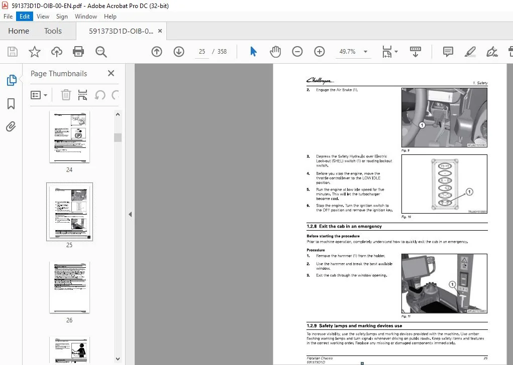
128 Exit the cab in an emergency25
129 Safety lamps and marking devices use 25
1210 Reading on public roads26
1211 Operate on a slope 26
1212 Electrical storm injury prevention 26
13 Maintenance and service 27
131 Maintenance safety 27
132 Wear protective clothing 31
133 Fire prevention and first aid 31
134 Proper disposal of waste 32
135 Shield and guards 32
136 Support the machine correctly 33
137 Asbestos information 33
138 Pressurized air 33
139 Cut and crush prevention 33
1310 Boom safety34
1311 Fuel safety 34
1312 Hydraulic safety 34
1313 High pressure leaks 35
1314 Chemical safety 35
1315 Engine safety 37
1316 Battery safety 39
1317 Tire safety 40
1318 Avoid eye contact with radar 40
1319 Exhaust fumes41
1320 Electrical power lines overhead 41
1321 Towing41
1322 Modifications41
1323 Mobile radio installation42
1324 Safety signs 42
14 Chassis safety signs 43
141 Electrocution hazard 44
142 Hot pressurized coolant44
143 Burn hazard 44
144 Rotating blades 44
145 Starter bypass 45
Flotation Chassis
591373010
Table of contents
146 Electrical hazard 45
147 Crush and falling hazard 45
148 Radar/ high pressure hazard 46
149 High pressure/ ether/ belt entanglement 47
15 Cab safety signs 48
151 Runover hazard 49
152 Sound horn / electrical hazard/ read manual 49
153 Rollover-seatbelt/ runover-no riders 49
16 Informational signs 50
161 Informational – Manufacturer plate 51
162 Informational – Tiedown 51
163 Ultra low sulfur diesel fuel 51
164 Informational – Hydraulic oil level 51
165 Informational – Alternate exit 52
166 Informational – Hand wash 52
167 Informational – Cab filter #2 and washer bottle 52
168 Informational – Cab filter #3 52
169 Informational – Cab filter #1 53
1610 Informational – Battery terminals 53
1 7 Informational electrical signs 54
171 Informational – Battery box fuse/ relay54
172 Informational – Cab fuse/ relay 54
2 Introduction 55
21 Information 57
211 Intended use57
212 Proper disposal of waste 57
213 Emissions reduction – selective catalyst reduction – SCR – technology 57
214 DEF Storage and Shelf Life 58
22 Machine identification 60
221 Product identification information 60
222 Serial number definition60
223 Engine serial number plate 61
224 Transmission serial number plate 61
23 Break-in period 62
231 General break-in information 62
232 Break-in maintenance schedule 62
233 Operate the engine-first 200 hours62
234 Initial interval for inline fuel strainer62
235 Break-in the transmission 62
236 Break-in the rear axle 62
237 Do a check of the rear axle mounting bolts 63
238 Do a check of the wheel mounting hardware 63
239 Hydraulic filter 63
2310 Initial pressure washer pump63
24 Machine transport 64
241 Operate the machine in limp-home mode 64
242 Transport the machine on a truck or trailer 67
243 Towing information 68
2431 Prepare for towing – engine operation 68
2432 Prepare for towing – engine not operating 71
2433 Tow the machine 71
25 Park brake information 73
251 Release the manual park brake 73
252 Release the park brake using air 73
253 Release the park brake by manually releasing the spring73
Flotation Chassis
591373010
Table of contents
26 Major components 76
261 Component location (front/rear view) 76
262 Component location (side view) 77
263 Component location (top view) 78
27 Emissions warranty 79
2 71 United States and Canada emission control warranty statement 79
272 California emission control warranty statement 82
3 Operation 87
31 Instruments and controls 91
311 Dash panel 91
312 Operating status displays 92
313 Multiple display screens92
314 Console keypad 94
315 Ignition switch94
316 Multifunction lever95
317 Set the windshield wiper delay 96
318 Tilt – telescoping lever 97
319 Foot pedals 97
3110 Park brake 98
3111 Drive lever controls 98
3112 Armrest controls 99
3113 Armrest adjustment 99
3114 Automatic heated mirrors99
3115 Power mirror adjustment 100
3116 Interior lamps 101
3117 Radio (if equipped) 101
3118 Sun Visor 101
3119 Cup holders101
3120 Storage compartments 102
3121 Power strip 102
3122 Power ports102
3123 Cargo net103
3124 Lamp switches 104
3125 Bluetooth microphone105
3126 Objects in the cab 105
3127 Automatic battery disconnect 105
32 Cab temperature control107
321 Automatic temperature control 107
322 Heater operation 108
323 Defroster operation 108
324 Air conditioner operation 108
325 Automatic fan speed control109
326 Manual fan speed control (HI/LO)109
327 Air conditioning compressor clutch control 109
328 Heater water valve 109
329 Cab air temperature sensor109
3210 Evaporator probe 110
3211 Temperature control troubleshooting 110
33 Seats 112
331 Seatbelt operation112
332 Basic operator seat 113
333 Deluxe operator seat 114
334 Deluxe vented operator seat116
335 Instructor seat 117
34 General inspection 119
341 Check flu ids119
Flotation Chassis
342 Check for Condition and Cleanliness 119
343 Do a check of the hydraulics119
344 Check fuel system 120
345 Do a check of the cab120
346 Check mirrors120
347 Check the Hoses120
348 Check the Safety Signs 120
Terminal introduction 122
Audible alarms and indicators 123
Display the chassis software information 123
Set the language124
Set the date and time 125
Set the audio level 126
Set the screen brightness 127
Switch between day and night mode 129
Call up the USB Data screen 129
Select and transfer individual data to the USB stick 130
Select and transfer all data to the USB stick 131
Transfer data from the USB stick to the terminal 132
Task data 133
Field data 134
Take a screenshot from the AccuTerminal 135
Download a screenshot from the AccuTerminal 135
Clean the terminal screen136
Calibrate the touch screen 137
Do a touch test 138
Set up the camera application – if equipped 139
View the service interval screens140
Program the user-defined service intervals140
Calibrate the radar 142
Calibrate the wheel speed 142
Calibrate the wheel speed and radar 143
Calibrate the steering angle sensor 144
Calibrate the steering valve 145
Calibrate the lever 146
Calibrate the transmission range 146
Calibrate the CVT transmission 147
Calibrate the turbo clutch 147
View the diagnostic screens148
View the active errors screen 149
Set the power management values 149
View the fuel consumption screen 150
Call up the ISOBUS Information screen151
View the Auto-Guide™ map152
View the worked area settings 153
Make a wayline from the map 154
35391 AB wayline 155
35392 Contour wayline 155
35393 A+ angle wayline 156
35394 Pivot wayline 157
35395 AB coordinates wayline 157
3540 Make a boundary from the map 157
3541 Make an obstacle from the map 159
3542 Adjust the Auto-Guide™ steering settings 161
3543 Update the terminal software 163
Raven Viper 4 values164
Camera settings166
Flotation Chassis
591373010
Table of contents
3 71 Camera options and connections 166
372 Position the camera image 167
373 Change cameras167
374 Display the camera image while reversing 168
375 Change the camera to and from full-screen 169
376 Adjust the brightness 169
377 Adjust the contrast 170
378 Adjust the color saturation171
38 Start the engine 172
381 Cold weather start procedure 173
382 Diesel exhaust fluid (DEF) cold start 174
383 Restart a stalled engine 174
384 Engine power limitations 174
385 Low diesel exhaust fluid (DEF) level 175
386 Stop the engine and afterrun176
39 Tag axle operation177
391 Tag axle 177
392 Operate the tag axle 177
310 Operate on a public road 178
3101 Machine operation on a public road 178
311 Transmission function 179
3111 Transmission – general179
3112 High and low speed range 179
3113 Drive the machine 180
3114 Drive modes 180
3115 Increase the drive speed 181
3116 Decrease the drive speed 182
311 7 Change the drive direction 183
3118 Stopthemachine 184
3119 Set the cruise control speeds 185
31110 Set the drive handle aggressiveness 186
31111 Transmission management system (TMS) 186
31112 Set the power management values 187
31113 Joystick mode 187
31114 Foot pedal throttle mode 188
312 AccuField Command 190
3121 Manual configuration 190
3122 General function -AccuField Command 191
3123 Functions and dependencies191
3124 Call up and activate AccuField Command 193
3125 Joystick assignment 194
3126 Record an operational sequence 195
3127 Start an operational sequence197
3128 Configure an operational sequence manually197
3129 Step mode 199
313 Cold weather considerations 201
3131 Minimize the effect of cold weather 201
3132 Using grade No 1-D fuel 201
3133 Fuel filters 201
3134 Coolant heater 201
3135 Seasonal viscosity oil and proper coolant concentration201
3136 Winterfronts 202
3137 Idling the engine202
3138 Engine coolant specifications 202
3139 Cooling system water quality 202
31310 Antifreeze 202
31311 Grease 203
Flotation Chassis
591373010
Table of contents
31312 Diesel fuel 203
31313 Lubricity of diesel fuels 203
31314 Diesel fuel storage 204
314 Storage205
3141 Prepare for long term storage 205
3142 Remove the machine from long term storage 205
315 Optional accessories207
3151 Weather station – if equipped 207
3152 Install the mini SIM card for Global System for Mobile communication (GSM)208
4 Engine Operation 211
41 Safety instructions 213
42 To the user 214
421 Engine type designations 214
422 Location of the engine serial number 215
423 Type plate of the electronic control unit 216
43 Technical data 217
431 Principal dimensions and data 217
432 Fuel system217
433 Lubrication system 217
434 Cooling system 217
435 Selective Catalyst Reduction (SCR) system technical data 218
44 Air control system 220
441 2 stage turbocharging 221
442 Interstage charge air cooling 221
443 Throttle valve221
45 Fuel system 222
46 Engine control system 224
4 7 Lubrication system 225
4 71 Oil pressure regulating valve 226
472 Oil filter and oil cooler226
48 Cooling system 227
481 Engine heater 227
49 Electrical system228
410 SCR system229
4101 Selective Catalyst Reduction (SCR) system overview 229
4102 Selective Catalyst Reduction (SCR) system components and their functions 230
411 Operation and driving 232
412 Daily pre-start check233
413 Starting the engine 234
4131 Break in the engine 234
414 Starting the engine in cold conditions236
4141 Warming up the engine 236
415 Start the engine with an auxiliary battery 237
416 Attention during operation 238
417 Stopping the engine239
5 Maintenance 241
51 Maintenance intervals 245
511 Maintenance introduction 245
512 Maintenance symbols245
513 Lubricant filling reminders 246
514 Maintenance schedule247
5141 Maintenance chart 247
Flotation Chassis
591373010
5142
5143
5144
Table of contents
Daily maintenance schedule 248
Maintenance schedule 10 to 1000 hours 248
Maintenance Schedule 2000 to 4000 hours 250
515 Lubricants and fluids 251
52 Air dryer and compressed air system 252
521 Air reservoir and air dryer 252
522 Replace the air dryer filter 252
53 Air conditioner system 254
531 Air conditioner 254
532 Condenser 254
54 Engine 255
541 Do a check of the engine oil255
542 Change the oil and oil filter 255
543 Engine belts and tensioner 256
5431 Replace the serpentine belt 256
5432 Replace the water pump belt 257
544 Fuel system259
545 Fuel tank 259
546 In-line fuel strainer 260
54 7 Replace the fuel filters260
548 Prime the fuel system261
549 Engine coolant 262
55 Air cleaner maintenance 264
551 Engine air cleaner indicator 264
552 Replace the air filter element 264
553 Secondary air filter element265
56 Hydraulic system 266
561 Do a check of the hydraulic oil-level check 266
562 Replace the hydraulic system oil and filter 266
57 Continuously variable transmission 268
5 71 Transmission operating temperatures 268
572 Do a check of the transmission oil 268
573 Change the transmission oil269
58 Driveline lubrication and U-joint inspection 271
581 Inspect and lubricate the engine to transmission driveline 271
582 Lubricate the transmission to rear axle driveline 272
59 lntercoolers 274
591 Heat exchangers274
592 Clean the heat exchangers 274
510 Wheel and axle bearings 276
5101 Lubricate the front wheel bearing276
5102 Tag axle bearing bolts and lubricate the tag axle fittings – if equipped 276
511 Tag axle277
5111 Tag axle bearing bolts and lubricating the tag axle fittings – if equipped277
512 Steering 278
5121 Steering cylinder278
513 Rear axle 279
5131 Clean the rear axle breather279
5132 Do a check of the rear axle oil 279
5133 Change the rear axle oil 280
514 Brake Maintenance 282
5141 Lubricate the brake slack adjuster282
5142 Brake air lines 282
5143 Parking brake282
5144 Do a check of the service brake system282
5145 Adjust the manual slack adjusters283
Flotation Chassis
591373010
Table of contents
51451 Brake adjustment procedure 284
515 Wheels 285
5151 Remove the front wheel 285
5152 Install the front wheel 287
5153 Remove the rear wheel 288
5154 Remove the rear wheel 289
5155 Install the rear wheel 290
5156 Tighten the wheel mounting hardware290
516 Tires 291
5161 Inflate the tire 291
5162 Replace the tire 291
5163 Tire chart 291
517 Cab maintenance 293
5171 Do a check of the cab mount bolts 293
5172 Cab air filters 294
5173 Change the primary fresh air filter295
5174 Change the secondary clean air filter 296
5175 Change the recirculation air filter298
5176 Clean the cab air filter element 299
5177 Do a check of the windshield washer reservoir 299
5178 Windshield wiper blade 300
518 Electrical system 301
5181 Batteries 301
51811 Remove the battery terminal connection 301
5182 Battery box components302
5183 Remove the battery terminal connection 303
5184 Jump start the battery304
5185 Change a fuse/relay 305
5186 Fuse/relay location 306
519 Paint and decals310
5191 Safety treads 310
520 Hand rinse tank 311
5201 Fill the hand rinse tank311
5202 Rinse hands and equipment312
5203 Winterize the hand rinse tank 312
521 Pressure washer 313
5211 Pressure washer input water supply 313
5212 Before starting the pressure washer 313
5213 Prime the pressure washer pump 313
5214 General care of the pressure washer pump 313
5215 Pressure washer pump storage in freezing conditions 313
5216 Operate the pressure washer 313
5217 Change the pressure washer pump motor oil 314
5218 Change the pressure washer strainer 315
5219 Winterize the pressure washer system 315
6 Troubleshooting 317
61 Engine 319
611 Low diesel exhaust fluid (DEF) level323
62 Transmission 324
63 Electrical system326
64 Hydraulic system 327
65 Parking brake troubleshooting 328
66 Operation 329
67 Cab 330
Flotation Chassis
591373010
Table of contents
68 TG7300C/TG8300C/TG8400C/TG9300C fault code reference 331
681 Accuterminal module fault code reference 331
682 Armrest module fault code reference 332
683 Automatic steering module fault code reference 332
684 Electrical controller module fault code reference 335
685 Error management module fault code reference 335
686 Machine information module fault code reference 336
687 Machine module fault code reference 336
688 Transmission module fault code reference 337
7 Specifications341
71 Machine specifications 343
72 Machine dimensions346
8 Index351
CHALLENGER EU APPLICATORS TERRAGATOR TG9300C FLOTATION CHASSIS OPERATOR’S MANUAL:
PLEASE NOTE:
- This is the SAME MANUAL used by the dealerships to diagnose your vehicle
- No waiting for couriers / posts as this is a PDF manual and you can download it within 2 minutes time once you make the payment.
- Your payment is all safe and the delivery of the manual is INSTANT – You will be taken to the DOWNLOAD PAGE.
- So have no hesitations whatsoever and write to us about any queries you may have : heydownloadss @gmail.com
S.V