
Cincinnati Arrow E/Dart Vertical Machining Centers Acramatic 2100E Operating Manual
Original price was: $39.95.$24.95Current price is: $24.95.
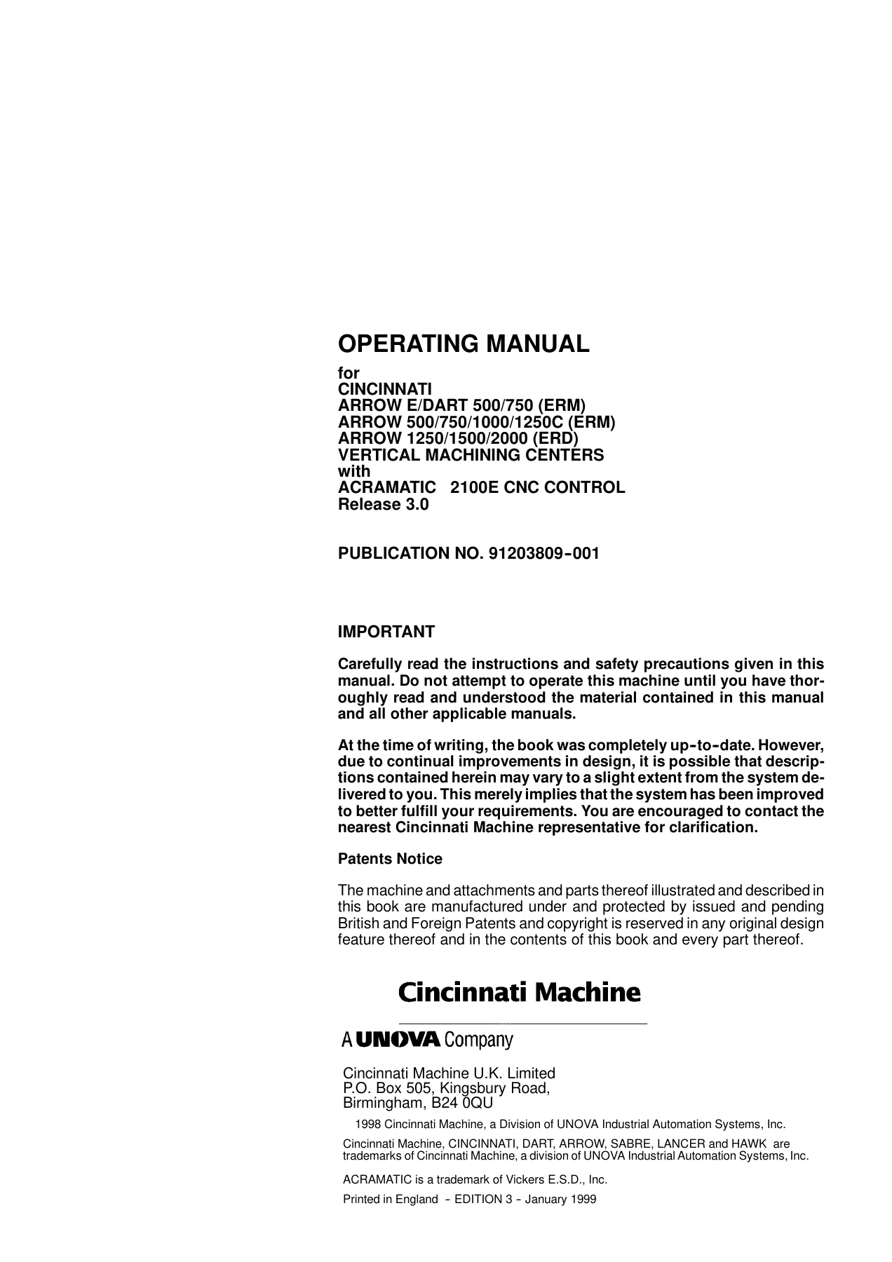
405-page Cincinnati Machine operating manual for ARROW E/DART 500/750 (ERM), ARROW 500/750/1000/1250C (ERM) and ARROW 1250/1500/2000 (ERD) vertical machining centers with ACRAMATIC 2100E CNC control. Covers machine specifications, control operation, tooling, offsets, setup, Workpiece Manager, program handling, diagnostics and reference data.
Description
Cincinnati Arrow E/Dart Vertical Machining Centers Acramatic 2100E Operating Manual
The Cincinnati Arrow E/Dart Vertical Machining Centers Acramatic 2100E Operating Manual is a detailed operating, setup and control reference for the Cincinnati ARROW E/DART and ARROW vertical machining center ranges fitted with the ACRAMATIC 2100E CNC control. It covers the ARROW E/DART 500/750 (ERM), ARROW 500/750/1000/1250C (ERM) and ARROW 1250/1500/2000 (ERD) machines, bringing together machine information, operating controls, setup procedures, workpiece management, tooling, program handling, diagnostics and A2100E reference data in one 405-page manual.
The manual is intended for suitably experienced personnel and repeatedly emphasizes safe machine operation, correct setup and proper use of the control. Alongside practical operator procedures, it includes model-specific machine specifications, table and travel drawings, spindle performance information, tool-holder data and detailed guidance for the ACRAMATIC 2100E interface.
File Details
- Manual type: Operating Manual
- Brand: Cincinnati Machine
- Models: ARROW E/DART 500/750 (ERM); ARROW 500/750/1000/1250C (ERM); ARROW 1250/1500/2000 (ERD)
- CNC control: ACRAMATIC 2100E
- Release: 3.0
- Publication number: 91203809–001
- Edition: 3
- Date: January 1999
- Language: English
- Pages: 405
- File format: PDF
Machine and Control Coverage
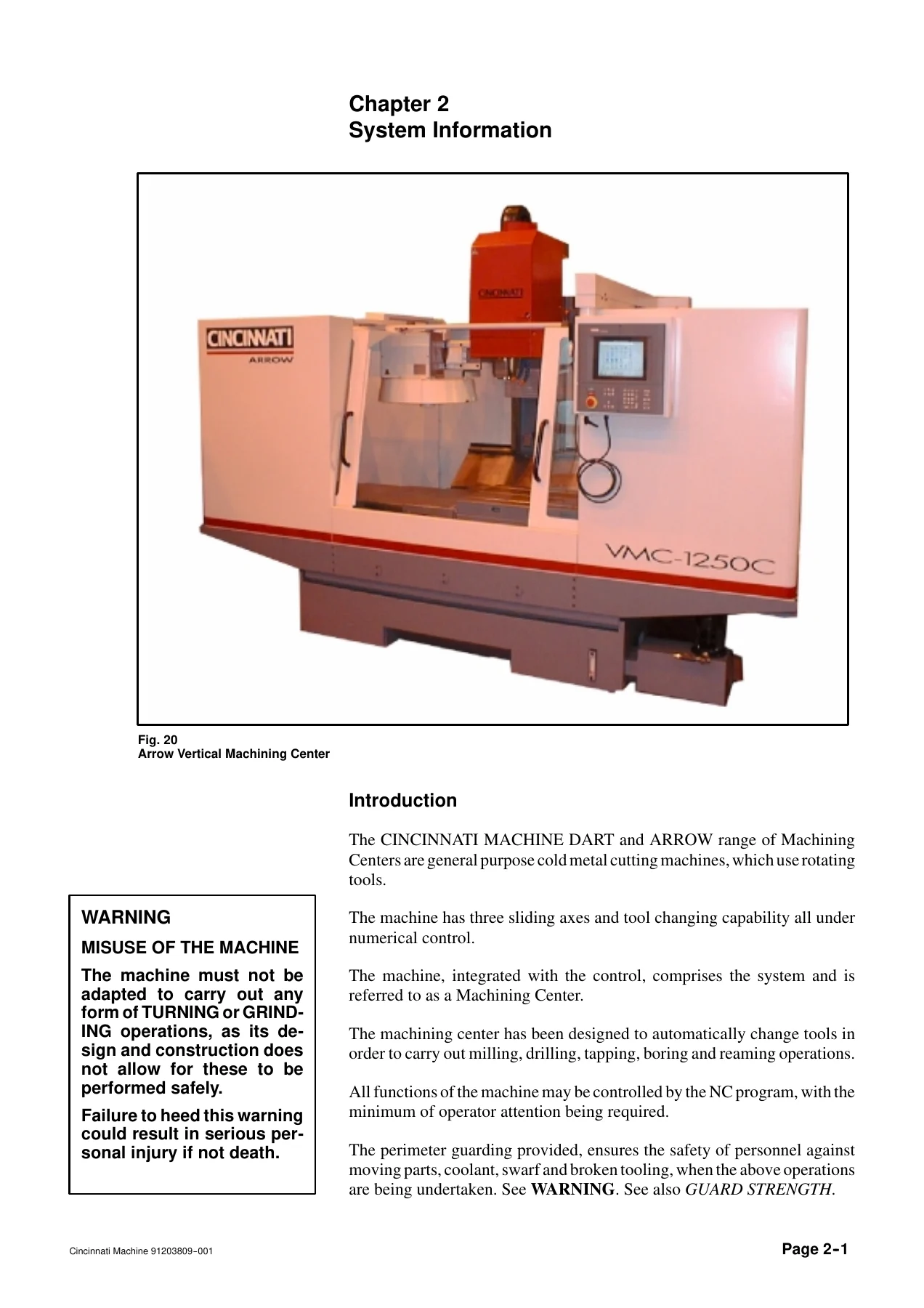
This operating manual explains the Cincinnati DART and ARROW machining centers as general-purpose cold-metal cutting machines with three sliding axes, numerical control and automatic tool changing. The covered machining operations include milling, drilling, tapping, boring and reaming. The machine information section identifies the X-axis table, Y-axis saddle and Z-axis spindle carrier, the automatic tool storage/changer, CNC station, electrical cabinet, coolant and swarf equipment, guarding and related operating hardware.
Model-specific specification pages cover axis travels, work surface dimensions and table load capacities, spindle speed ranges and motor ratings, rapid traverse rates, positioning and repeatability data, tool storage capacities, coolant delivery, air requirements, electrical loads, machine weights and floor-space information. Separate range drawings illustrate the ARROW E/DART 500/750, ARROW 1000/1250C and ARROW 1250/1500/2000 configurations. Tool-holder sections include No. 40 holder standards, retention stud dimensions and torque information, while spindle power charts show standard, optional high-speed and high-torque ranges where applicable.
ACRAMATIC 2100E Operation and Setup
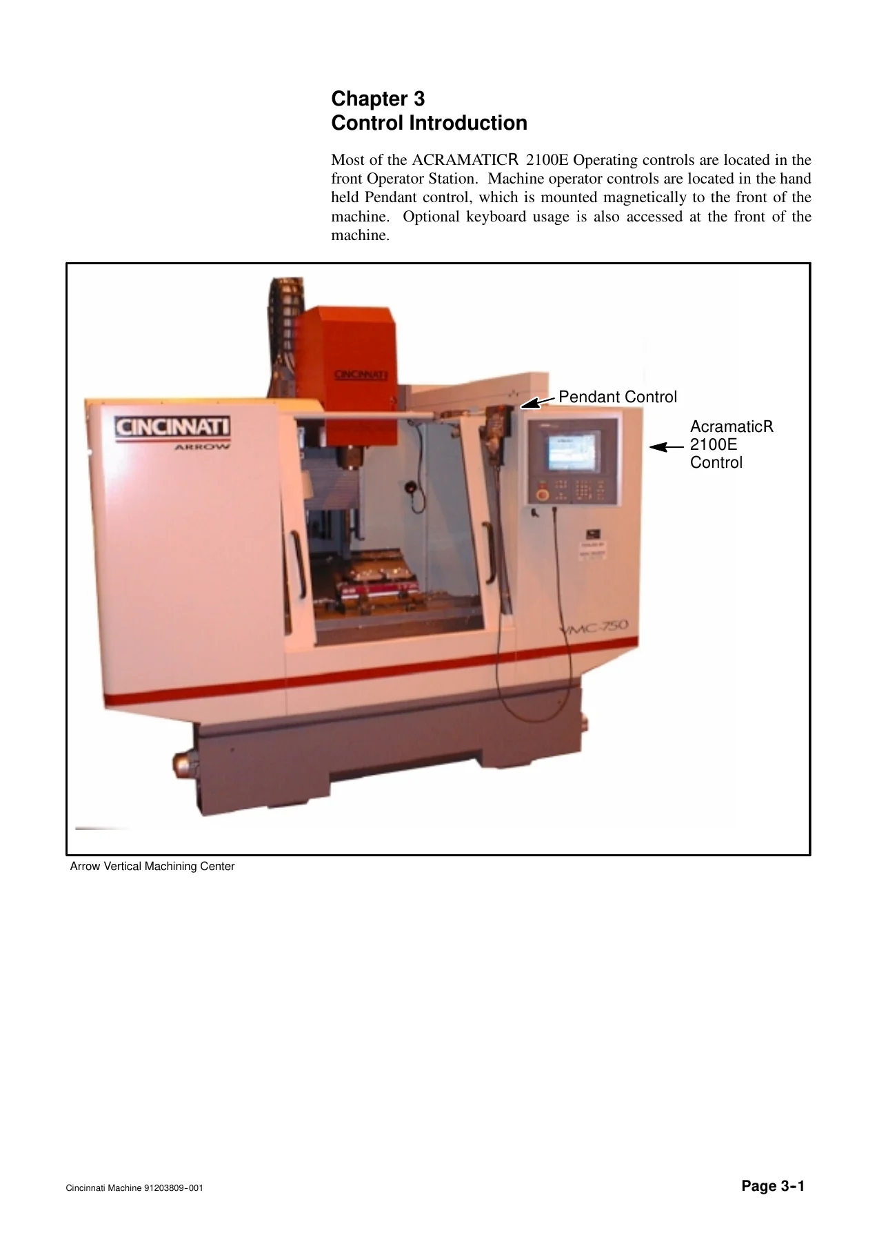
A major part of the Cincinnati Arrow E/Dart Vertical Machining Centers Acramatic 2100E Operating Manual is devoted to the A2100E operator interface. It explains the operator station, touch screen, keypad and machine pendant, then walks through the production display, current display, status bar, machine mode, program editing, RAP Resident Assistant Programmer, tooling, multi-setup functions, diagnostics, service access, system configuration and file management.
Practical setup information is unusually extensive. The manual describes machine alignment, axis jogging and power feed, handwheel movement, overtravel recovery, data entry, MDI operation, tool loading and unloading, tool tables, tram-surface setup, tool-length setting, coordinate resets and program activation. Workpiece Manager coverage explains pallet, setup and fixture relationships, multiple work faces, probe cycles and machining sequence control. Offset guidance covers pallet offsets, multiple-setup offsets, fixture offsets and NC program offsets, including how those offset layers interact.
Chapters Covered
- Chapter 1 – Safety Precautions
- General safety instructions, personal safety, work area safety and tool safety
- Lifting and carrying, installation and relocation, setup and operation, and maintenance safety
- Lifting devices: eyebolts, hoist rings, spreader bars, chains, cable slings, synthetic slings and lifting hooks
- Machine-tool fluids, lubricants, cutting fluids, coolant maintenance, water quality, filtering and rust prevention
- Printed circuit board handling instructions
- Safety features, perimeter guarding, operator doors, feed hold, emergency stop and isolation devices
- Machine-related safety notes, spindle tooling, tool drum operation, levelling, foundation bolting and lithium batteries
- Chapter 2 – System Information
- Machine construction, location, NC control and axis orientation
- Guard strength, noise, workpiece handling, coolant misting and fire-hazard information
- ARROW E/DART (ERM), ARROW (ERM) and ARROW (ERD) specifications
- Machine range drawings and table dimensions
- Tool holders, retention studs and JMTBA-BT tooling
- Motor ratings and 6000, 8000, 10000 and 5000 rpm spindle performance ranges
- Chapter 3 – Control Introduction
- Operator station, OSA keypad, machine on/off, emergency stop and control screen
- Machine, Edit, RAP, SFP, Tools, Multi-Setup, Diagnostics, Service and System Configuration modes
- Touch screen, keyboards, plotter display and help functions
- Axis, offset and other control displays
- Pallet, multiple-setup, fixture, NC program and machine offsets
- Tool Manager, Active Tool Set, Tool File, tool loading, tool geometry and tool magazine functions
- Program management, directory services and NC program storage
- Machine pendant controls, main electrical cabinet and optional swarf/coolant operating devices
- Chapter 4 – General Setup Guide
- Machine startup, system configuration and machine alignment
- Operator-station functions, MDI, tooling, axis jog/power feed and workpiece setup
- Tram-surface and tool-length setup
- Finding, loading, creating, editing, copying and plotting part programs
- Operating checks, dry run and running a part program
- Axis alignment, mechanism alignment and automatic realignment
- Workpiece Manager, fixtures, setups, pallets, work faces and probe cycles
- Multiple Setup feature, offset definition and execution
- Chapter 5 – Other Setup Information
- Axis display and axis inhibit procedures
- Plotter setup, program plotting and tool-movement tracking
- Program and file management, backup, restore, copy, rename and delete operations
- Program Editor functions including search/replace, cut/copy/paste and resequencing
- RAP session creation, editing, saving, loading and NC program generation
- Program Translator setup
- Display calibration, Home Menu changes, NC programming execution and security levels
- PC connection to the A2100E, cycle search/recovery, program and cycle parameters, parts counter and probe calibration
- Appendix A – Program Reference Data
- Block-word and Type II listings, G-code and M-code tables
- Drilling-cycle parameters, tool data and system table names
- Parameter variables, pallet and multiple-setup tables, fixture/tool/program/machine offsets and arithmetic functions
- Appendix B – System Configuration
- Security and NC programming execution options
- Cutter Diameter Compensation configuration and alarm reporting
- Circular and linear mode settings and optional M70-M79 user M-code execution
Taken as a whole, the document combines day-to-day operator instruction with the setup logic and reference information needed to work effectively with these Cincinnati machining centers and the ACRAMATIC 2100E. It is especially useful when the operator needs to move between machine setup, tooling, offsets, program preparation, controlled trial operation, production execution and control-side troubleshooting without relying on scattered references.
Useful Procedures and Reference Material
The manual goes beyond basic button descriptions. It gives step-by-step sequences for switching power on and off, aligning axes and mechanisms, jogging and power-feeding axes, using the handwheel, loading tools, setting tool lengths, establishing coordinate positions, running dry checks and executing part programs. It also documents how the A2100E handles program directories, editing, external program sources, file backup and restore, RAP-assisted programming and PC communication.
For setup work, the offset and Workpiece Manager material is particularly valuable. Operators can follow the relationships between pallet offsets, setup offsets, fixture offsets and NC program offsets, then apply those concepts to multi-setup machining, fixture patterns, pallet sequencing and probe cycles. Reference appendices provide quick access to G codes, M codes, drilling-cycle parameters, tool-data fields and system tables when a control function or program element needs to be checked.
Operate, Set Up and Run the Machine with the Correct Reference
The Cincinnati Arrow E/Dart Vertical Machining Centers Acramatic 2100E Operating Manual supports the practical work of preparing the machine, configuring the control, aligning axes and mechanisms, managing tooling and offsets, loading or editing programs, checking motion, using diagnostics and running machining cycles on the covered ARROW and DART models. Having the correct procedures, model specifications and A2100E control references available matters when setup accuracy, safe operation and repeatable machining depend on entering the right values and following the intended sequence.
Delivered as an instant PDF after purchase, there is no shipping delay. Open the manual on a computer, tablet or phone, keep it available beside the machine, and print the pages you need for workshop reference.
IMAGES PREVIEW
Reviews
There are no reviews yet.