
CLAAS Arion 640-510 Electrical Services Chapter F Diagnostics Manual 2010
Original price was: $39.95.$23.95Current price is: $23.95.
Official CLAAS Arion 640-510 Electrical Services Chapter F Diagnostics manual covering serial ranges from No.A1801259/A1902417. Complete wiring diagrams, connector pinouts, fuse allocations, relay layouts, function diagrams, and implantation diagrams for Arion 640 to 510 tractors.
Description
CLAAS Arion 640-510 Electrical Services Chapter F Diagnostics Manual
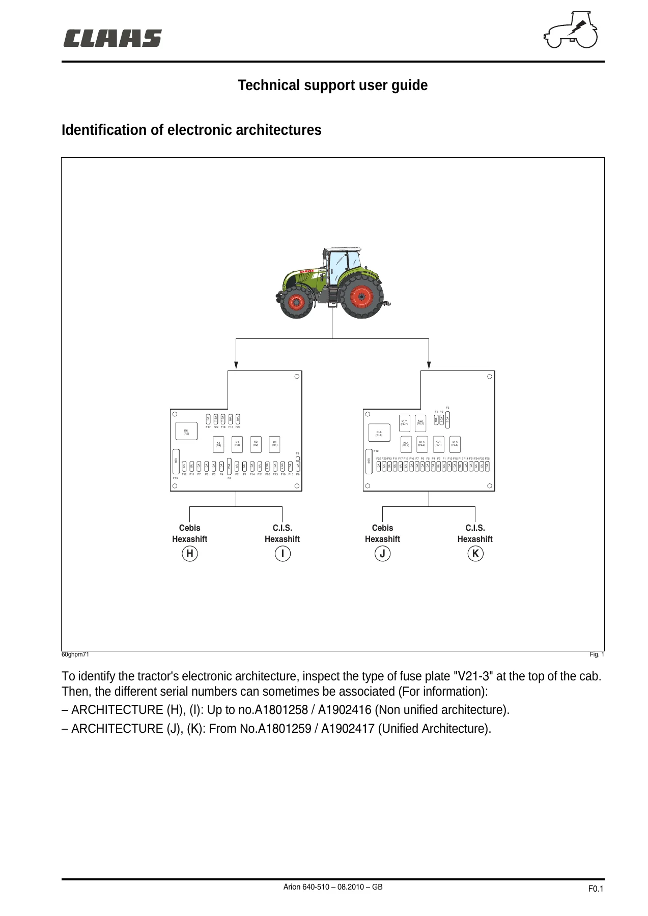
This CLAAS Arion 640-510 Electrical Services Chapter F Diagnostics manual is the complete electrical diagnostics resource for Arion 640 through Arion 510 tractors. Published August 2010 and covering serial ranges from No.A1801259/A1902417 (unified architecture), this manual gives technicians, electricians, and owners the full electrical system documentation needed for accurate diagnosis, repair, and maintenance of these machines.
File Details
- Manual Type: Electrical Services Chapter F — Diagnostics
- Brand: CLAAS
- Models Covered: Arion 640, Arion 510 (Arion 640-510 series)
- Document Number: 0011379331
- Date: 08.2010 (August 2010)
- Language: English (GB)
- Page Count: 456 pages
- File Format: PDF
- Serial Ranges: From No.A1801259 / A1902417 (Unified Architecture); Up to No.A1801258 / A1902416 (Non-Unified Architecture)
Chapters Covered
The CLAAS Arion 640-510 Electrical Services Chapter F Diagnostics manual is organized into four major sections that together form a complete electrical diagnostic system for the Arion 640-510 tractor range.
F0 — General
- CLAAS Component Numbers (CCN) list — modules, sensors, switches, relays, fuses, potentiometers, solenoids, and connectors
- List of connectors — complete J-series connector designations for cab, transmission, engine, hydraulic, lighting, and auxiliary circuits
- List of harnesses — all numbered harness assemblies from cab bottom to ISOBUS and engine injection
- Grounding points — full grounding stud and earth point locations
- Relay allocation — K-series and KL-series relay assignments for cab bottom and cab top fuse plates
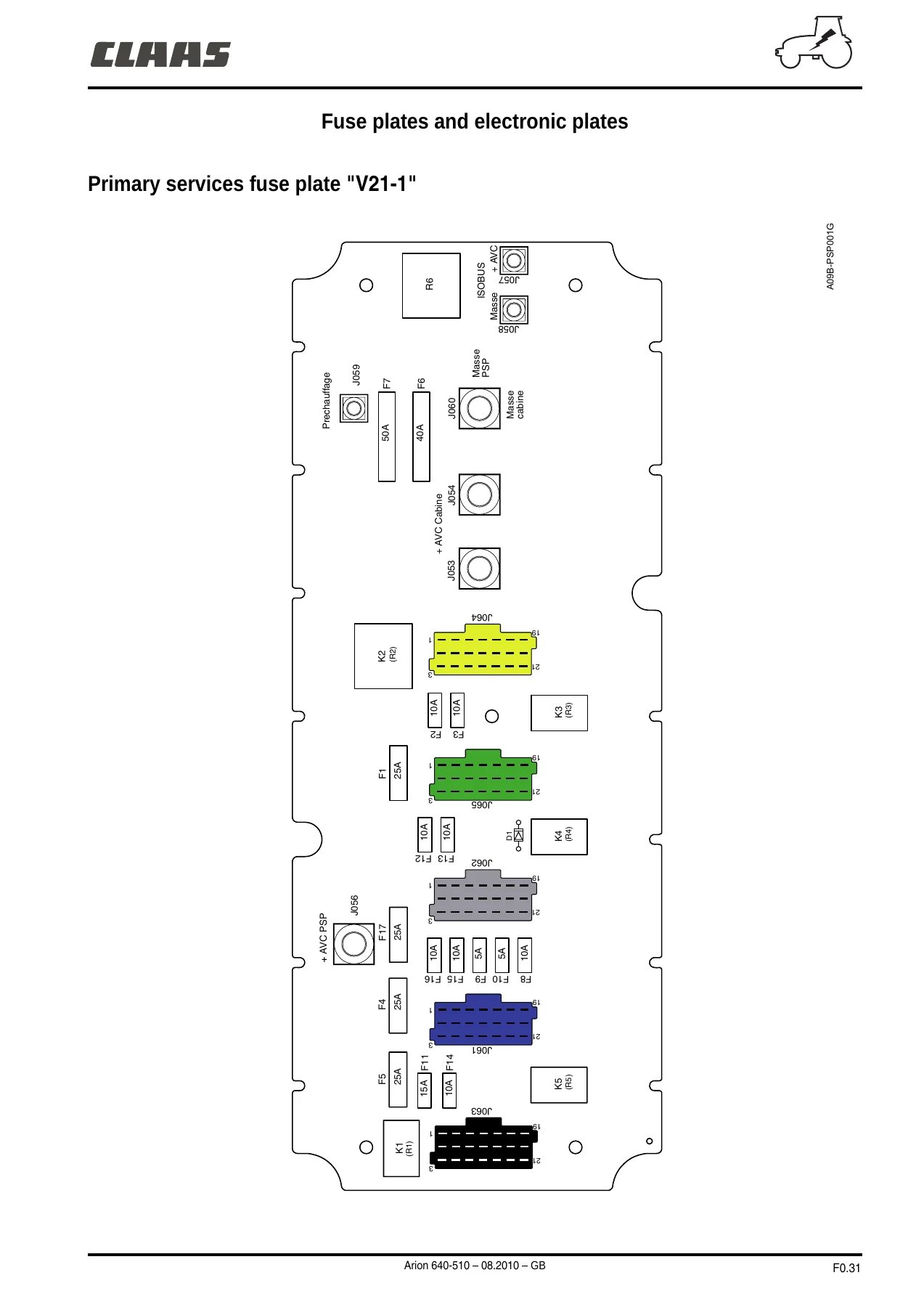
- Allocation of fuses — fuse positions, ratings, and circuit protection assignments for V21-1, V21-2, and V21-3 fuse plates
F1 — Function Diagrams
- Work lights — front and rear cab roof, rear fender, railing, and grille work lights
- Road signalling — position lights, police plate lights, dipped headlights, main beam lights, brake lights, rotating beacons, horn, flashing indicators, hazard warning lights, instrument panel lighting, and low beam on railing
- Ventilation and A/C — manual air conditioning and automatic A/C circuits
- Lift — front linkage, rear lift (including Arion 640-specific variants)
- Power take-off — front PTO, rear PTO, 540/1000, 540/540 Eco/1000, and proportional 540/1000 PTO load circuits
- Transmission — forward/reverse, starter safety device, robot-driven ranges, 4-wheel drive control, differential control, crawl range, hydraulic pressure and filter clogging (Load Sensing and Open Centre), transmission temperature, Hexashift, and work/transport mode
- Accessories — cigarette lighter, radio, overhead light
- Wiper/washer — front windscreen wash/wipe and rear screen wiper/washer
- Defrosting — rear window defrost and power mirror circuits
- Rear view mirrors — electric rear view mirror circuits
- Networks — K and L lines, Powertrain CAN bus (Cebis and C.I.S. options), CLAAS vehicle CAN bus, Hydraulic CAN bus, and ISOBUS CAN
- Supply — supply before contact, supply after contact (high pressure + pneumatic braking, CUNA braking), earth circuits, work light module power supply, transmission module power supply, rear lifting module power supply, front suspended axle module power supply, UBM hydraulic module power supply, engine module power supply, diagnostic socket power supply, automatic AC module power supply, multifunction armrest module power supply, terminal module power supply, electrodistributor module power supply, dashboard module power supply, and Hexashift display module power supply
- 25 A power sockets — front, rear, and cab
- 7 pin ISO connector, event counter connector, ISOBUS socket, rear trailer socket, front trailer socket, and charger socket
- Brake system — pneumatic brake, CUNA braking, high pressure braking, handbrake
- Seat — pneumatic seat, heating seat, presence sensor
- Transmission speed — theoretical forward speed and transmission load
- Suspension — front suspended axle
- Levels — fuel gauge and brake fluid level
- Engine — oil pressure, air filter clogging, temperatures, electronic injection (4- and 6-cylinder), exhaust gas recycling (EGR), variable geometry turbocharger (VGT), and management of powers
- Instrument panel — calibration, control panel display selector (Cebis), dashboard display selector (C.I.S.), real driving speed, and dashboard alarms
- Electrohydraulic spool valves — external controls (rear)
- Automation — CLAAS Sequence Management
F2 — Connector Diagrams
- Complete pin-out diagrams for every connector on the Arion 640-510 electrical system
- Wire numbers, wire cross-sections (mm²), designations, tip references, and state information
- Covers cab ground, internal transmission harness, transmission control harness, inner control harness, cab bottom harness, cab top harness, cab supply harness, ISOBUS harness, pre-heating, panel earth, under cab harness, transmission harness (Load Sensing and Open Centre), engine harness (4- and 6-cylinder), rear windscreen washer pump, front windscreen washer pump, fuel level, trailer socket, rear tool power socket, clutchless reverser potentiometer, clutch pedal switch, handbrake, accelerator potentiometer, tractor speed sensor, dephased motor speed sensor, rear PTO speed sensor, rear PTO brake solenoid valve, rear PTO solenoid, high-pressure oil filter, differential lock solenoid valve, 4-wheel drive solenoid valve, range solenoid valves, transmission oil temp sensor, Hexashift solenoid valves, stop contacts, signalling control, clutchless reverser control, wiper/washer control, fan control, air conditioning controls, temperature sensors, front wiper motor, hazard warning lights switch, cigarette lighter, events counter, implement electrical socket, forward/reverse solenoid valves, key contact, low beam switch, hydraulic module, external functions module, engine computer, pressure switch, compressor, door switches, diagnostic socket, ISOBUS socket, loudspeaker, electrohydraulic lifting control panel, armrest, CAN connectors, PTO speed control, lighting connectors, rotating beacons, working lights, police plates, headlights, mirrors, dome lights, radio, loudspeakers, antenna earth, rear axle pressure switch, gearbox pressure switch, defrosting, rear wiper, front PTO solenoid valve, buttons, sensors, valves, and more
- Splices N001 through N133 with wire assignments and tip references
- Interconnection harness mappings (P001-J001 through P483-J483)
F3 — Implantation Diagrams
- Cab bottom harness (automatic A/C and manual air conditioning)
- Instrument panel harness (automatic A/C and manual air conditioning)
- Fender harness
- Cab top harness (automatic A/C and manual air conditioning)
- Under cab harness
- Suspended front axle harness
- Cab supply harness
- Internal transmission harness
- Load Sensing and Open Centre transmission harnesses
- Engine harness (4-cylinder and 6-cylinder)
- Radiator cowling harness
- Electronic injection harness (4-cylinder and 6-cylinder)
- Transmission control harness
- Inner control harness (standard and with options)
- Electrohydraulic lift harness
- Front electrohydraulic lifting and front PTO harness
- Rear work light harness
- Railing harness
- Right console harness
- Police plate harness
- Dipped light tilting harness
- Air brake harness, CUNA braking harness, high pressure braking harness, high pressure + pneumatic braking harness
- Rotating lights harness
- Internal supply harness
- Proportional control shunt
- Outer options harness
- Defrosting mirror harness
- Hexashift display harness
- Upper cab shunt CAN
- ISOBUS harness
- Clear level harness
- Alternator adapter harness
- Electrohydraulic distributor termination, link, and main harnesses
- Timing sensor adapter harness
- Cab tools power outlet harness
- Harness extension for electrohydraulic lifting and front PTO
- Cigarette lighter harness
- Radar adapter
- Sensor harness of rear electrohydraulic lifting position (Arion 640 only)
- Command harness ISOBUS
- Low beam shunt
- LH console harness (standard and with options)
- Supply cables C1 through C8b
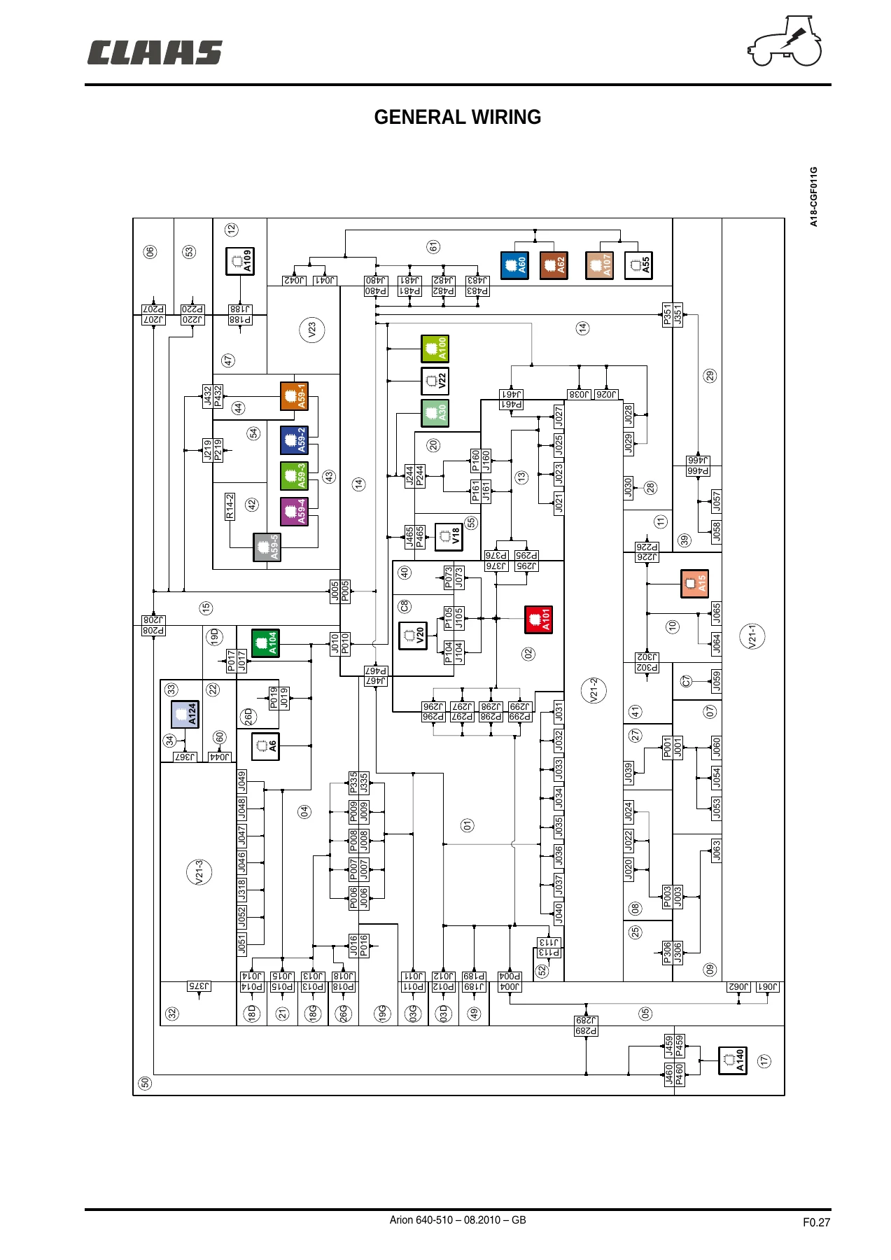
What sets this CLAAS Arion 640-510 Electrical Services Chapter F Diagnostics manual apart is the depth of diagnostic information it provides. Rather than generic electrical theory, every diagram is specific to the Arion 640-510 platform, with actual wire numbers, connector designations, fuse ratings, and component codes. The manual begins with a complete CLAAS Component Numbers list — every module, sensor, switch, relay, potentiometer, solenoid, and connector is assigned a code that appears throughout the diagrams. This means a technician can trace any circuit from the fuse plate through the harness, through each connector pin, to the component, and back to ground, using consistent identifiers at every step.
The function diagrams (F1) show how each electrical system operates as a complete circuit — not just individual wires but the logic of how power flows, how relays and switches interact, and how control modules communicate over CAN networks. For tractors with the optional Cebis or C.I.S. terminals, separate diagrams cover Powertrain CAN, Vehicle CAN, Hydraulic CAN, and ISOBUS CAN, making network diagnostics possible rather than just circuit testing. The supply diagrams break down every power source — before contact, after contact, and the various braking configurations — so voltage-drop and parasitic-draw problems can be traced to their source.
The connector diagrams (F2) are the heart of the manual for anyone doing pin-level testing. Each connector entry shows the connector number, a visual representation of the plug, the pin numbering, the wire number, the wire cross-section, the circuit designation, the tip (destination) reference, and the state. This level of detail means you can identify not just which pin carries which signal, but also the exact wire gauge and the path the wire takes through the harness. Splices and interconnections are similarly detailed, with every wire junction documented.
What This Manual Enables You to Do
With the CLAAS Arion 640-510 Electrical Services Chapter F Diagnostics manual, you can:
- Diagnose electrical faults systematically using function diagrams and connector pinouts
- Trace circuits from fuse to component to ground using consistent wire numbers and component codes
- Identify the correct fuse, relay, or connector for any electrical circuit on the tractor
- Test CAN bus networks (Powertrain, Vehicle, Hydraulic, ISOBUS) with correct pin assignments
- Repair or replace electrical components with confidence in connector pinouts and wire assignments
- Understand power supply circuits for all major modules and control units
- Locate grounds and grounding points for proper electrical system maintenance
- Work on lighting systems — work lights, road signalling, rotating beacons, and more
- Service air conditioning and ventilation electrical circuits (manual and automatic)
- Troubleshoot transmission, PTO, hydraulic lift, and front axle suspension electrical systems
- Diagnose engine management electrical circuits including EGR and VGT systems
- Interpret instrument panel and dashboard electrical circuits
Why It Matters
Electrical faults on modern agricultural tractors can be some of the most time-consuming and frustrating problems to diagnose without proper documentation. The CLAAS Arion 640-510 Electrical Services Chapter F Diagnostics manual eliminates guesswork. Every circuit is documented with the exact wire numbers, connector pinouts, fuse ratings, and component codes used in the actual machine. Whether you are chasing an intermittent fault, repairing damage, or adding an accessory, having the correct wiring diagram and connector reference is essential for safe and effective work.
This is not a generic electrical guide. It is the specific diagnostic documentation for the Arion 640-510 platform, covering both the unified architecture (from serial No.A1801259/A1902417) and providing information for earlier non-unified architectures. The manual includes serial number ranges so you can verify you are using the correct diagram for your machine.
Delivery
The CLAAS Arion 640-510 Electrical Services Chapter F Diagnostics manual is delivered as an instant PDF download. There is no shipping, no waiting, and no physical media. The PDF can be viewed on any device — computer, tablet, or smartphone — and individual pages or sections can be printed for use in the workshop. Whether you are a professional technician, a farm owner maintaining your own equipment, or someone restoring an Arion tractor, this manual provides the electrical diagnostic information you need, when you need it.
Reviews
There are no reviews yet.