
CLAAS Celtis 426 436 446 456 Diagnostic Manual 6005029688 (2005) PDF
Original price was: $49.95.$29.95Current price is: $29.95.
Comprehensive 876-page diagnostic manual for CLAAS Celtis 426, 436, 446 and 456 tractors, covering DPS engines and injection, drivetrain, axles, hydraulics, steering, electrical/electronic systems, cab systems, front PTO/lift and air brakes. Includes specifications, schematics, diagnostic charts, adjustments and illustrated repair procedures.
Description
CLAAS Celtis 426 436 446 456 Diagnostic Manual 6005029688 (2005) PDF is a comprehensive technical reference for diagnosing, adjusting, testing, removing, installing and repairing the Celtis 426, 436, 446 and 456 tractors. Its coverage spans from fuel injection and DPS engines through clutches, gearboxes, axles, hydraulics, steering, electrical systems, electronic management, cab systems, front PTO/lift and air brakes. The manual combines specifications and checking values with schematic diagrams, exploded views, diagnostic flow charts, adjustment procedures and illustrated workshop operations.
File Details
- Manual type: Diagnostic manual
- Brand/models: CLAAS Celtis 426, 436, 446 and 456
- Language: English
- Page count: 876 pages
- File format: PDF
- Document number: 60 05 029 688
- Edition/revision dates shown: 10.2003, 03.2004 and 05.2005
Model and Engine Coverage
The manual identifies the tractor variants Celtis 426 – M 3612, Celtis 436 – M 3622, Celtis 446 – M 3632 and Celtis 456 – M 3642. Injection and engine sections cover electronic-injection DPS 4045 DRT 70, 4045 TRT 70, 4045 TRT 71 and 4045 TRT 72 engines, together with mechanical-injection DPS 4045 DRT 76, 4045 TRT 77 and 4045 TRT 78 applications. The injection data includes fuel supply layouts, pump and injector information, PTO engine test curves and checking conditions for the applicable Celtis models.
Engine data in the CLAAS Celtis 426 436 446 456 Diagnostic Manual 6005029688 (2005) PDF includes 4-cylinder DPS engine identification, dimensional specifications, tightening data and service checks. The manual gives bore, stroke and displacement information, lubrication and cooling data, compression checks, oil-pressure checks, valve adjustment procedures, turbocharger pressure checks and numerous wear limits and clearances needed when inspecting or rebuilding engine components.
Chapters Covered
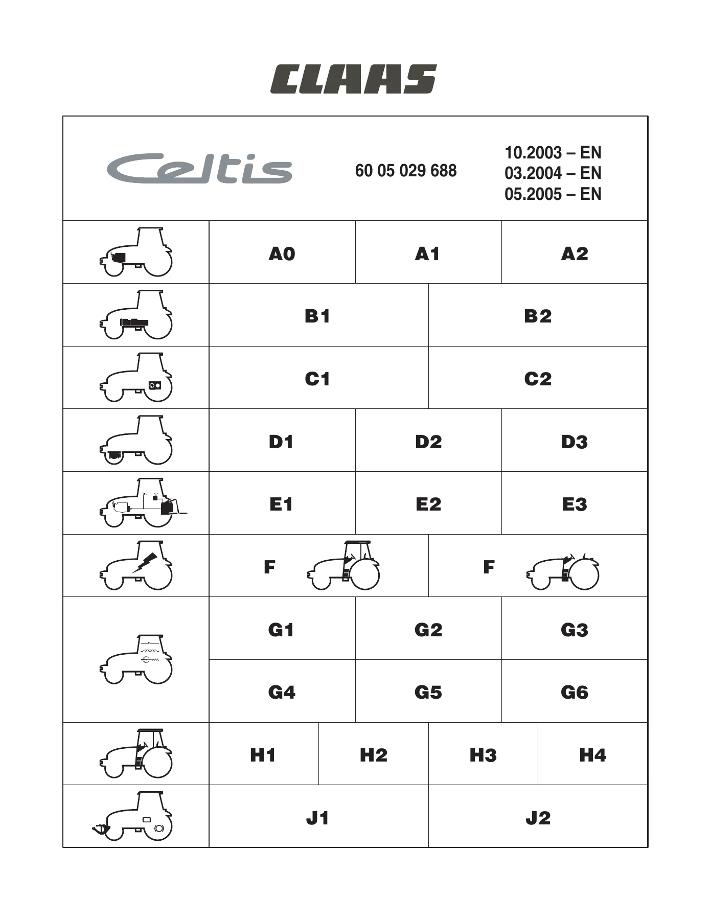
- A0 – Injection Data Sheets and Checking Procedure
- Electronic and mechanical injection sheets; PTO power testing; measurement/checking points; hydraulic pressure checks; dynamic injection adjustment.
- A1 – Injection Feed
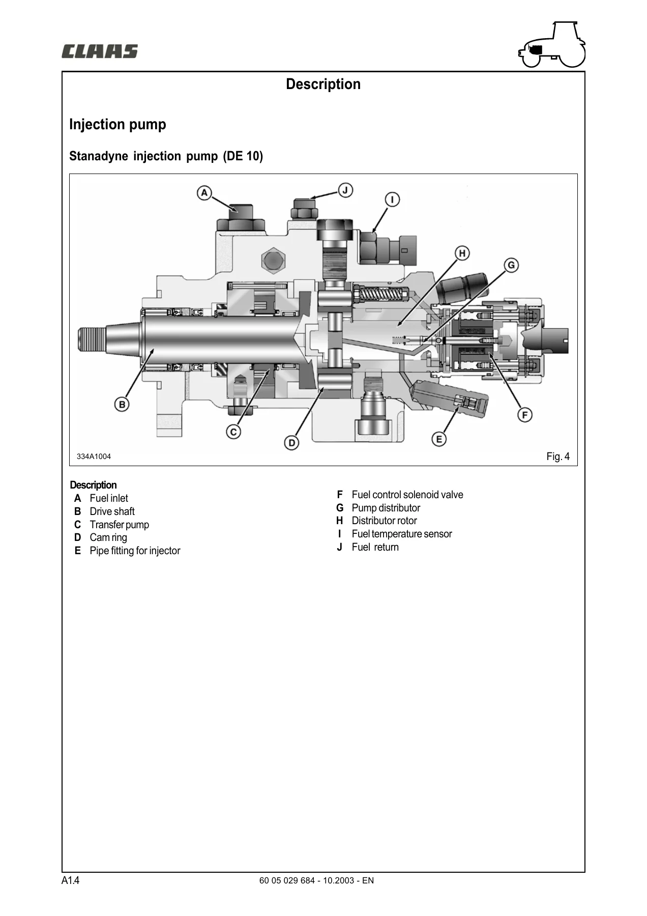
- Primary and fuel filters; injection pump and injectors; sensors; accelerator adjustment; supply-pressure testing; bleeding; pump/injector removal and installation; fuel-system diagnostics.
- A2 – DPS Engine
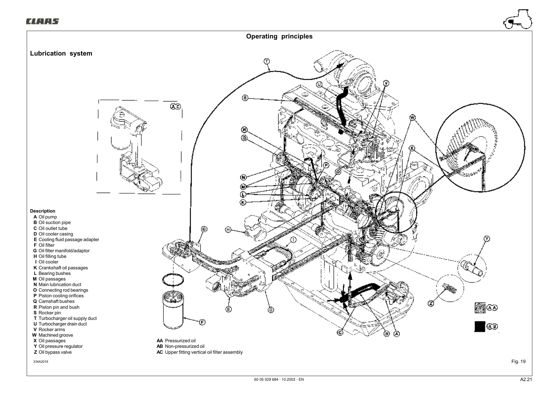
- General and dimensional specifications; cylinder head, valves, block, liners, pistons, connecting rods, crankshaft, camshaft and gear train; lubrication, cooling, turbocharger, overhaul, diagnostics and special tools.
- B1 – Drive and Power Take-Off Clutches
- Mechanical clutch and Revershift hydraulic-control PTO clutch inspection, removal, installation, release adjustment, clearance and shaft/bearing work.
- B2 – B41 Gearboxes
- Mechanical and hydraulic gearbox kinematics; gearbox controls; Revershift and Twinshift housings; reverser, doubler, shafts, gears, ranges, shimming and adjustment operations.
- C1 – Rear Axle
- Specifications, kinematics, exploded views, differential and crown wheel service, bearing preload, half-shaft work, differential lock and adjustments.
- C2 – Oil-Bath Disc Brakes
- Brake specifications, tightening values, removal/installation and operating brake and handbrake adjustments.
- D1 – Front Axle
- Axle specifications and kinematics; wheel alignment; reducers, wheel hubs, planetary gears, differential, pivots, universal-joint shafts and preload/backlash adjustments.
- D2 – M21 Power Take-Off Housing
- Housing removal/installation, Belleville spring shimming, piston-stroke shimming, bearing-clearance adjustment and 4WD housing clutch-release control.
- D3 – Front Axle
- Specifications, axle assembly, steering cylinder and wheel-alignment adjustment.
- E1 – Hydraulics
- 48 l/min and 60 l/min circuit specifications; Revershift and non-Revershift schematics; auxiliary distributors; brake valve; filters, strainer, bleeding, pump replacement and check-value sheets.
- E2 – Lift and Hitch
- Mechanical and electronic lift controls; main distributor; lift casing, arm and piston; internal controls; linkage diagnostics for no-lower, no-lift/slow-lift and jerking conditions.
- E3 – Steering
- Load-sensing steering, priority valve, steering unit and cylinder; pressure-restricter and surge-damping valves; pump-flow checks and steering diagnostic sheets.
- F – Electricity
- Item lists, wiring/general lists, function-based schematic diagrams, harness routing, connector tracking and electricity tools.
- G1-G6 – Electronic Systems and Diagnostic Application
- Engine management, transmission management, TCE 9 electronic lift, combined instrument panel, INFOTRAC and METADIAG diagnostic application.
- H1-H4 – Cab and Platform Systems
- Cab lift, heating/air conditioning, window bonding and platform lift, including safety, service procedures and HVAC diagnostics.
- J1 – Front PTO and Lift
- Specifications, tightening torques and removal/installation procedures.
- J2 – Air Brake
- Operating states, compressor, pressure regulator, control valves, trailer brake control and air-brake bleeding.
Together, these chapters make the manual useful for systematic troubleshooting as well as component-level repair. A technician can move from a symptom or diagnostic code to circuit checks, pressure or flow measurements, electrical schematics, adjustment values and the corresponding removal or installation procedure. Exploded views and illustrated procedures support mechanical work, while the diagnostic sheets provide decision paths for conditions such as engine starting failure, irregular running, exhaust smoke, lack of power, oil-pressure faults, overheating, steering problems and lift-system faults.
Engine, Injection and Measurement Work
The engine and injection sections are particularly detailed. The manual provides fuel-system layouts for both electronic and mechanical injection configurations, injector calibration information, pump data and PTO performance test sheets. It also explains pre-test checks for oil levels, filters, battery condition, radiator cleanliness, turbocharger pressure, hydraulic pressure and dynamometer setup so that measured performance can be compared under controlled conditions. Dynamic injection adjustment procedures show how timing is checked and corrected, while the injection-feed chapter covers filter replacement, system bleeding, injection pump service access, injector removal/installation and injector adjustments.
IMAGES PREVIEW
For internal engine work, the manual goes beyond basic maintenance. It contains dimensional drawings and limits for cylinder head and valves, cylinder block, liners and pistons, connecting rods, crankshaft and bearings, camshaft and distribution components. Removal and installation sequences cover major engine assemblies, including cylinder head service, liner protrusion measurement, piston and connecting-rod work, bearing and flywheel procedures, front and rear seals, distributor casing, balancer shafts, oil pump, water pump, thermostat, belt drive and turbocharger checks. Lubrication and cooling system diagrams help trace oil and coolant flow during diagnosis.
Transmission, Axle and Hydraulic Diagnosis
The drivetrain coverage addresses mechanical clutch systems, Revershift hydraulic-control PTO clutch arrangements, B41 gearboxes and their mechanical or hydraulic operating layouts. Procedures include clutch inspection, shaft service, control adjustment, input-housing work, reverser and doubler service, gear/range work and shimming. Rear- and front-axle chapters provide exploded views, torque and adjustment information, differential and crown-wheel procedures, wheel-hub and planetary work, bearing preload, backlash and wheel-alignment checks.
Hydraulic sections document circuit versions for tractors with and without Revershift transmission, including 48 l/min and 60 l/min specifications. They cover auxiliary distributors, brake valve adjustments, filtration, pump replacement and pressure/flow checking. Lift and hitch material includes mechanical and electronic control systems plus diagnostic paths for slow or absent lift, failure to lower and unstable or jerking operation. Steering coverage adds load-sensing components, priority-valve checks, pump-flow checks and fault-finding for heavy steering, vibration, oscillation and repeated path correction.
Electrical and Electronic Troubleshooting
Electrical coverage is organized around item lists, wiring references, functional schematics, harness routing and connector locations. The electronic-system chapters add engine-management component locations and sensor specifications, transmission management, TCE 9 electronic lift, instrument-panel functions and INFOTRAC. METADIAG is referenced within diagnostic procedures where electronic fault codes or operating data must be checked. This combination helps connect a mechanical symptom to the associated sensor, wiring path, control unit or hydraulic/mechanical subsystem rather than treating each system in isolation.
Workshop Capability and Instant PDF Access
The CLAAS Celtis 426 436 446 456 Diagnostic Manual 6005029688 (2005) PDF supports fault tracing, measurement, adjustment and major repair across the tractor’s engine, injection, clutch, gearbox, axle, brake, hydraulic, steering, electrical, electronic and cab systems. It is especially valuable when a repair depends on the correct sequence, pressure, clearance, torque, test condition or diagnostic path instead of trial-and-error replacement. Use the manual to plan work, confirm specifications, follow component removal and installation procedures, interpret schematics and diagnose system faults with the checks provided for the Celtis range.
Delivery is by instant PDF after purchase, with no physical shipping. The file can be opened on compatible phones, tablets and computers and pages can be printed when a workshop copy is convenient.
Reviews
There are no reviews yet.