Description
CLAAS Celtis 426 436 446 456 Technical Support & Diagnostic Manual – 09.2007 PDF
The CLAAS Celtis 426 436 446 456 Technical Support & Diagnostic Manual – 09.2007 PDF is a wide-ranging technical reference for the Celtis tractor family. Its 887 PDF pages bring together engine support, B41 transmission information, axles, hydraulic systems, rear lift and steering, electrical services, instrument-panel and Metadiag diagnostics, cab and air-conditioning material, plus front-mounted equipment and pneumatic braking. The material is organised as a set of technical-support chapters rather than a short operator handbook, with system descriptions, schematics, dimensional data, checking procedures, adjustment values and fault-finding routines throughout.
Coverage shown in the manual includes Celtis 426, Celtis 436, Celtis 446 and Celtis 456. Engine material identifies 4045DRT76, 4045TRT77, 4045TRT78 and 4045 TRT 72 variants in the relevant procedures and dimensional data. The transmission section covers the B41 family and its mechanical-reverser, Revershift and Twinshift configurations, including 30 km/h and 40 km/h versions, slow-range arrangements and associated hydraulic/electronic controls.
File Details
- Manual type: Technical support and diagnostic reference
- Brand / model: CLAAS Celtis
- Models shown: Celtis 426, 436, 446, 456
- Edition: 09.2007
- Language: English (GB); the H1 cab-lifting section is presented in French
- Page count: 887 pages
- File format: PDF
- Document references: 00 11 354 320 on the principal technical-support chapters; Chapter B is 00 11 354 310; the G3 Metadiag 2007 manual is 00 11 359 400
Technical Depth and Diagnostic Content
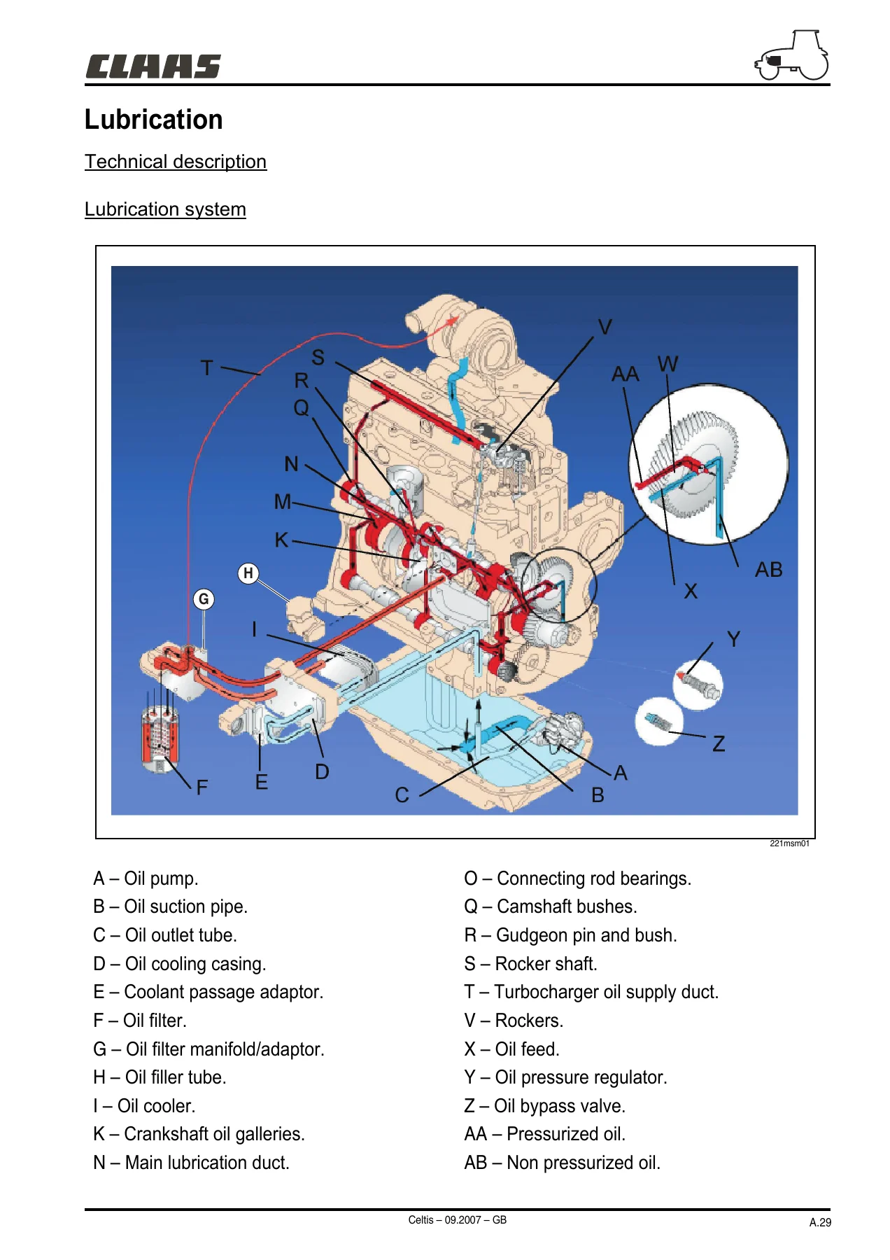
This Celtis technical support manual is built around practical system understanding and test work. In the DPS engine chapter, the manual moves from inlet/exhaust construction and cooling/lubrication circuits into mechanical and electronic injection, component identification, sensor checks, pump operation and engine-management logic. Diagnostic sheets cover conditions such as engine failure to start, erratic running, grey or black smoke, white smoke, fuel-supply faults, lack of power, excessive oil consumption, abnormal oil pressure and cooling problems. Procedures include compression testing, valve-lift checks, turbocharger pressure checks, thermostat testing, sensor measurements and use of specified test equipment.
The engine data is detailed enough for inspection and repair decisions. Examples include cylinder-head and valve dimensional limits, oil-pump delivery and pressure figures, thermostat opening values, turbocharger checks, injector calibration values, piston/liner clearances, connecting-rod and crankshaft measurements, camshaft limits and viscous-fan checks. Electronic-injection material also explains DE 10 pump operation, the crankshaft-position and temperature sensors, pump-control solenoid, ECU inputs and outputs, pre-heating logic, idle automation, protection modes and SAE J1939 fault-code transmission.
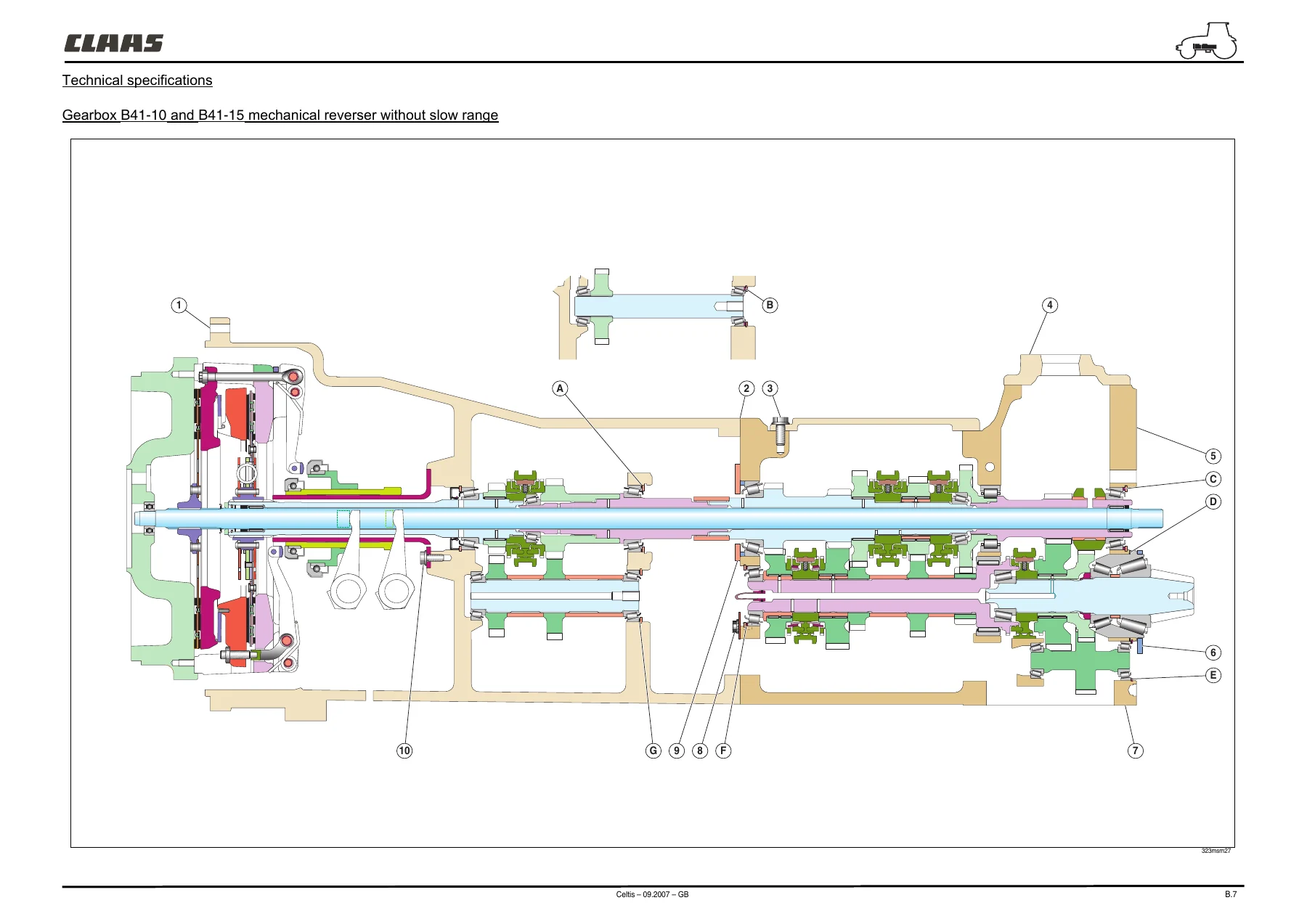
Transmission coverage is similarly broad. The B41 chapter identifies gearbox variants, clutch arrangements, operating diagrams, torque settings and adjustment procedures. Revershift sections explain forward/reverse clutch operation, hydraulic pressure action, sensors, proportional solenoid valves, AUTO 5 control, calibration and fault logic. Twinshift material explains the hydraulic doubler, hare/tortoise states, pressure and ratio behaviour, electronic control and overspeed protection. Mechanical reverser, mechanical doubler, slow range, gear/range selection, synchronisers and control locking are also included.
Beyond the powertrain, the manual covers rear and front axle assemblies, PTO systems, oil-immersed brakes, steering geometry, differential operation and front/rear inter-axle preponderance. Hydraulic chapters document 48 and 60 l/min open-centre systems, Revershift and non-Revershift layouts, pump flow/pressure test points, steering circuits, mechanical and electronic rear-lift systems, TCE9 control, and auxiliary spool valves. Electrical Services adds fuse/relay information, conductor allocations, system-by-system wiring schematics, connector and harness tracking and electricity-tool references.
The diagnostic material continues through the instrument panel, Infotrac and the included Metadiag 2007 chapter. Metadiag coverage includes version updates, connections, engine and transmission applications, engine overview, fault history, error-code lists, DE 10 programming, transmission electrical tests, adjustments, programming and parameter setting. This gives the buyer both mechanical troubleshooting paths and electronic diagnostic context in one large reference.
Chapters Covered
- Chapter A – DPS Engine
- Inlet and exhaust
- Cooling
- Lubrication
- Mechanical injection
- Electronic injection, including hydraulic part and electronic components
- Moving assembly
- Accessory gear train
- Viscous fan coupling
- Chapter B – Gearbox B41 and Clutch LUK DT 310 – 310 G
- Mechanical vehicle drive clutch
- Revershift function: mechanical, hydraulic piloting and electronic components
- Twinshift function: mechanical, hydraulic piloting and electronic components
- Mechanical reverser and mechanical doubler
- Slow range
- Speeds and ranges
- Chapter C – Rear Axle
- Crown wheel, pinion and differential
- Rear power take-off
- Mechanical PTO clutch
- Hydraulically controlled PTO clutch Revershift
- Brakes
- Chapter D – Front Axle
- Differential
- Power take-off
- Wheel swivel pin
- Undriven front axle
- Chapter E – Hydraulics and Controls
- E1: 48 and 60 l/min hydraulics, with and without Revershift transmission
- E2: rear lift, rear mechanical lifter TCM and electronic rear lifter TCE9
- E3: steering
- E4: auxiliary spool valves
- Chapter F – Electrical Services
- Item lists and wiring/general lists
- Schematic diagrams according to functions
- Connector and harness tracking
- Fuse, relay and conductor-allocation information
- Electricity tools
Complete PDF Bookmark Tree
Complete Bookmarks
The complete bookmarks in the “CLAAS Celtis 426 436 446 456 Technical Support & Diagnostic Manual – 09.2007 PDF” are as follows:
+A Diagnostic.pdfp. 1
+B Diagnostic.pdfp. 123
Gearbox B41 and clutch LUK DT 310 – 310 Gp. 123
+B – Gearbox B41 and clutch LUK DT 310 – 310 Gp. 127
+Gearboxp. 129
Mechanical vehicle drive clutchp. 159
+Revershift functionp. 162
Mechanical Partp. 162
Hydraulic piloting partp. 169
Electronic componentsp. 170
+TWINSHIFT functionp. 196
Mechanical Partp. 197
Hydraulic piloting partp. 202
Electronic componentsp. 202
Mechanical reverserp. 213
Mechanical doublerp. 222
Slow rangep. 223
Speeds and rangesp. 224
+C Diagnostic.pdfp. 232
Rear axlep. 232
+C – Rear axlep. 236
+Rear axlep. 238
Crown wheel and pinion and differentialp. 242
+Rear power take-offp. 245
Mechanical PTO clutchp. 247
Hydraulically controlled PTO clutch Revershift®p. 253
Brakesp. 256
+D Diagnostic.pdfp. 260
+D – Front axlep. 260
+Front axlep. 266
Differentialp. 272
Power take-offp. 274
Wheel swivel pinp. 276
Undriven front axlep. 278
+E Diagnostic.pdfp. 280
E1 – Hydraulicsp. 280
E2 – Rear liftp. 280
E3 – Steeringp. 280
E4 – Auxiliary spool valvesp. 280
+E1 – Hydraulicsp. 282
+48 and 60 l/min hydraulicsp. 286
Tractor without transmission Revershift®p. 289
Tractor with transmission Revershift®p. 316
E2 – Rear liftp. 340
+Rear liftp. 344
+Rear mechanical lifter (TCM)p. 344
Mechanical Partp. 344
Hydraulic partp. 348
+Electronic rear lifter TCE9p. 363
Mechanical Partp. 363
Hydraulic partp. 366
Electronic componentsp. 368
+E3 – Steeringp. 380
+E4 – Auxiliary spool valvesp. 396
+F Diagnostic.pdfp. 418
+F1p. 418
+F2p. 422
Item listp. 423
Wiring and general listsp. 424
+CONTENTSp. 427
Fuse and relay boxp. 428
Fuse and relay boxp. 429
Conductor allocationsp. 429
Conductor allocations (cont)p. 430
Starting/load/preheating/mechanical reverser circuit (Electronic injection)p. 431
Starting/load/preheating/mechanical reverser circuit (Electronic injection)p. 432
Starting/load/preheating/mechanical reverser circuit (Mechanical injection)p. 433
Starting/load/preheating/mechanical reverser circuit (Mechanical injection)p. 434
Start-up circuit/REVERSHIFT (Electronic injection)p. 435
Start-up circuit/REVERSHIFT (Electronic injection)p. 436
Start-up circuit/REVERSHIFT (Mechanical injection)p. 437
Start-up circuit/REVERSHIFT (Mechanical injection)p. 438
Side lights / Instrument panel light / Hornp. 439
Side lights / Instrument panel light / Hornp. 440
Tilting of dipped headlights High / Cab bottomp. 441
Tilting of dipped headlights High / Cab bottomp. 442
Rotating beaconsp. 443
Rotating beaconsp. 444
Front work lights / Rear work lightsp. 445
Brake lights / Engagement/front axle controls / Air brake system solenoid valve control / Handbrake / Theoretical speedp. 447
Brake lights / Engagement/front axle controls / Air brake system solenoid valve control / Handbrake / Theoretical speedp. 448
Flashing lights and warning lightsp. 449
Flashing lights and warning lightsp. 450
Cigar lighter/Radio / Cab light and spotp. 451
Cigar lighter/Radio / Cab light and spotp. 452
Pneumatic seat / Front power take-off control / Loader single lever supplyp. 453
Pneumatic seat / Front power take-off control / Loader single lever supplyp. 454
Front windscreen wiper/washer with fixed steering columnp. 455
Front windscreen wiper/washer with fixed steering columnp. 456
Front and rear windscreen wiper/washer with adjustable steering columnp. 457
Instrument panel ventilationp. 458
Instrument panel ventilation / Air conditioningp. 459
Instrument panel ventilation / Air conditioningp. 460
INFOTRAC on-board computerp. 461
Fuel/air filter clogging/temperature/engine oil pressure indicator (Electronic injection)p. 462
Fuel/air filter clogging/temperature/engine oil pressure indicator (Electronic injection)p. 463
Fuel/air filter clogging/temperature/engine oil pressure indicator (Mechanical injection)p. 464
Fuel/air filter clogging/temperature/engine oil pressure indicator (Mechanical injection)p. 465
Engine speedp. 466
Engine speedp. 466
Control panel display/diagnostic socket selection (REVERSHIFT)p. 467
Control panel display/diagnostic socket selection (REVERSHIFT)p. 468
Control panel display/diagnostic socket selection (Mechanical reverser)p. 469
Control panel display/diagnostic socket selection (Mechanical reverser)p. 470
25 A power socketp. 471
Transmission hydraulic pressurep. 472
Transmission hydraulic pressurep. 473
Rear PTO controlsp. 474
Rear PTO controlsp. 475
TCE 9 Liftp. 476
TCE 9 Liftp. 477
Revershift/doubler clutch and drive controlsp. 478
Revershift/doubler clutch and drive controlsp. 479
Engine managementp. 480
Engine managementp. 481
Hydraulic dual range unitp. 482
Hydraulic dual range unitp. 482
Hydraulic dual range unitp. 483
+F3p. 484
+CONTENTSp. 486
0/1 – Cab bottom harnessp. 490
0/1 – Cab bottom harness (Clutchless reverser)p. 490
0/1 – Cab bottom harness (mechanical reverser)p. 491
0/1 – Cab bottom harnessp. 491
0/1 – Cab bottom harnessp. 492
0/1 – Cab bottom harnessp. 492
0/1 – Cab bottom harnessp. 493
0/1 – Cab bottom harnessp. 493
0/1 – Cab bottom harnessp. 494
0/1 – Cab bottom harnessp. 494
0/1 – Cab bottom harnessp. 495
0/1 – Cab bottom harnessp. 495
0/1 – Cab bottom harnessp. 496
0/1 – Cab bottom harnessp. 496
0/1 – Cab bottom harnessp. 497
0/1 – Cab bottom harnessp. 497
Windscreen wiper/Screen washer/Dashboard display selectionp. 498
Windscreen wiper/Screen washer/Dashboard display selectionp. 498
3/1 – electronic injection enginep. 499
3/1 – electronic injection enginep. 499
3/1 – electronic injection enginep. 500
3/1 – electronic injection enginep. 500
3/1 – electronic injection enginep. 501
3/1 – electronic injection enginep. 501
3/1 – electronic injection enginep. 502
3/1 – mechanical injection enginep. 503
3/1 – mechanical injection enginep. 503
3/1 – mechanical injection enginep. 504
3/1 – mechanical injection enginep. 504
3/1 – mechanical injection enginep. 505
3/1 – mechanical injection enginep. 505
3/2 – Preheating control harnessp. 506
3/2 – Preheating control harnessp. 506
3/3 – Radiator cowling harnessp. 507
3/3 – Radiator cowling harnessp. 507
3/4 – Air brake harnessp. 508
3/4 – Air brake harnessp. 508
5 – Cab top harnesp. 509
5 – Cab top harnesp. 509
5 – Cab top harnesp. 510
5 – Cab top harnesp. 510
5 – Cab top harnesp. 511
5 – Cab top harnesp. 511
5 – Cab top harnesp. 512
7a – Transmission harness with reverser under torque "REVERSHIFT"p. 513
7a – Transmission harness with reverser under torque "REVERSHIFT"p. 513
7a – Transmission harness with reverser under torque "REVERSHIFT"p. 514
7a – Transmission harness with reverser under torque "REVERSHIFT"p. 514
7a – Transmission harness with reverser under torque "REVERSHIFT"p. 515
7b – Transmission harness, mechanical reverser with mechanical or hydraulic doublerp. 516
7b – Transmission harness, mechanical reverser with mechanical or hydraulic doublerp. 516
7b – Transmission harness, mechanical reverser with mechanical or hydraulic doublerp. 517
7b – Transmission harness, mechanical reverser with mechanical or hydraulic doublerp. 517
8a – Transmission control harness with reverser under torque "REVERSHIFT"p. 518
8a – Transmission control harness with reverser under torque "REVERSHIFT"p. 518
8a – Transmission control harness with reverser under torque "REVERSHIFT"p. 519
8a – Transmission control harness with reverser under torque "REVERSHIFT"p. 519
8a – Transmission control harness with reverser under torque "REVERSHIFT"p. 520
8a – Transmission control harness with reverser under torque "REVERSHIFT"p. 520
8a – Transmission control harness with reverser under torque "REVERSHIFT"p. 521
8b – Transmission controls harness, mechanical inverter with mechanical or hydraulic doubler / Electro-hydraulic liftp. 522
8b – Transmission controls harness, mechanical inverter with mechanical or hydraulic doubler / Electro-hydraulic liftp. 522
8b – Transmission controls harness, mechanical inverter with mechanical or hydraulic doubler / Electro-hydraulic liftp. 523
8b – Transmission controls harness, mechanical inverter with mechanical or hydraulic doubler / Electro-hydraulic liftp. 523
8b – Transmission controls harness, mechanical inverter with mechanical or hydraulic doubler / Electro-hydraulic liftp. 524
8b – Transmission controls harness, mechanical inverter with mechanical or hydraulic doubler / Electro-hydraulic liftp. 524
8b – Transmission controls harness, mechanical inverter with mechanical or hydraulic doubler / Electro-hydraulic liftp. 525
8b – Transmission controls harness, mechanical inverter with mechanical or hydraulic doubler / Electro-hydraulic liftp. 525
8b – Transmission controls harness, mechanical inverter with mechanical or hydraulic doubler / Electro-hydraulic liftp. 526
9/1 – Ground of electrohydraulic lifting command harnessp. 527
9/1 – Ground of electrohydraulic lifting command harnessp. 527
9/1 – Ground of electrohydraulic lifting command harnessp. 528
9/1 – Ground of electrohydraulic lifting command harnessp. 528
9/1 – Ground of electrohydraulic lifting command harnessp. 529
9/1 – Ground of electrohydraulic lifting command harnessp. 529
9/2 – Ground of front electrohydraulic liftingp. 530
9/2 – Ground of front electrohydraulic liftingp. 530
9/2 – Ground of front electrohydraulic liftingp. 531
Electricity toolsp. 534
Electricity toolsp. 534
+F1 Arcp. 536
+F2 Arcp. 540
Item listp. 541
Wiring and general listsp. 542
+CONTENTSp. 544
Fuse and relay boxp. 545
Conductor allocationsp. 546
Starting/load/preheating/mechanical reverser circuit (Electronic injection)p. 547
Starting/load/preheating/mechanical reverser circuit (Electronic injection)p. 548
Starting/load/preheating/mechanical reverser circuit (Mechanical injection)p. 549
Starting/load/preheating/mechanical reverser circuit (Mechanical injection)p. 550
Start-up circuit/charge/(REVERSHIFT) (Electronic injection)p. 551
Start-up circuit/charge/(REVERSHIFT) (Electronic injection)p. 552
Start-up circuit/charge/(REVERSHIFT) (Mechanical injection)p. 553
Start-up circuit/charge/(REVERSHIFT) (Mechanical injection)p. 554
Side lights/dipped headlights/headlights/control panel lighting/hornp. 555
Side lights/dipped headlights/headlights/control panel lighting/hornp. 556
Rear working light/rotating beaconp. 557
Brake lights/front axle engagement/hand brakep. 559
Brake lights/front axle engagement/hand brakep. 560
Flashing lights and warning lightsp. 561
Flashing lights and warning lightsp. 562
Front power take-off controlp. 563
Fuel/air filter clogging/temperature/engine oil pressure indicator (Electronic injection)p. 565
Fuel/air filter clogging/temperature/engine oil pressure indicator (Electronic injection)p. 566
Fuel/air filter clogging/temperature/engine oil pressure indicator (Mechanical injection)p. 567
Fuel/air filter clogging/temperature/engine oil pressure indicator (Mechanical injection)p. 568
Engine speedp. 569
Control panel display/diagnostic socket selectionp. 570
25 A power socketp. 571
Transmission hydraulic pressurep. 572
Rear PTO controlsp. 573
Revershift/doubler clutch and drive controlsp. 575
Revershift/doubler clutch and drive controlsp. 576
Hydraulic dual range unitp. 577
Engine managementp. 579
Engine managementp. 580
+F3 Arcp. 582
+CONTENTSp. 583
0/1 – Instrument panel harnessp. 585
0/1 – Instrument panel harnessp. 586
0/1 – Instrument panel harnessp. 587
0/1 – Instrument panel harnessp. 588
0/1 – Instrument panel harnessp. 589
3/1 – electronic injection enginep. 590
3/1 – electronic injection enginep. 591
3/1 – electronic injection enginep. 592
3/1 – mechanical injection enginep. 593
3/1 – mechanical injection enginep. 594
3/2 – Preheating control harnessp. 595
3/3 – Radiator cowling harnessp. 596
3/4 – Air brake harnessp. 597
0/5 – Platform/Roll bar harnessp. 598
0/5 – Platform/Roll bar harnessp. 599
7a – Transmission harness, REVERSHIFT reverserp. 600
7a – Transmission harness, REVERSHIFT reverserp. 601
7b – Transmission harness, mechanical reverser with mechanical or hydraulic doublerp. 602
7b – Transmission harness, mechanical reverser with mechanical or hydraulic doublerp. 603
8a – Transmission controls harness, Revershift inverterp. 604
8a – Transmission controls harness, Revershift inverterp. 605
8a – Transmission controls harness, Revershift inverterp. 606
8b – Transmission controls harness, mechanical inverter with mechanical or hydraulic doublerp. 607
8b – Transmission controls harness, mechanical inverter with mechanical or hydraulic doublerp. 608
Electricity toolsp. 611
Electricity toolsp. 611
+F1 Diagnostic.pdfp. 612
General contentsp. 614
+Item list wiring and general listsp. 616
Item listp. 617
Wiring and general listsp. 618
+Schematic diagrams according to functionsp. 619
Contentsp. 620
Fuse and relay boxp. 621
Conductor allocationsp. 622
Starting/load/preheating/mechanical reverser circuit (Electronic injection)p. 623
Starting/load/preheating/mechanical reverser circuit (Electronic injection)p. 624
Starting/load/preheating/mechanical reverser circuit (Mechanical injection)p. 625
Starting/load/preheating/mechanical reverser circuit (Mechanical injection)p. 626
Start-up circuit/charge/(REVERSHIFT) (Electronic injection)p. 627
Start-up circuit/charge/(REVERSHIFT) (Electronic injection)p. 628
Start-up circuit/charge/(REVERSHIFT) (Mechanical injection)p. 629
Start-up circuit/charge/(REVERSHIFT) (Mechanical injection)p. 630
Side lights/dipped headlights/headlights/control panel lighting/hornp. 631
Side lights/dipped headlights/headlights/control panel lighting/hornp. 632
Rear working light/rotating beaconp. 633
Brake lights/front axle engagement/hand brakep. 635
Brake lights/front axle engagement/hand brakep. 636
Flashing lights and warning lightsp. 637
Flashing lights and warning lightsp. 638
Front power take-off controlp. 639
Fuel/air filter clogging/temperature/engine oil pressure indicator (Electronic injection)p. 641
Fuel/air filter clogging/temperature/engine oil pressure indicator (Electronic injection)p. 642
Fuel/air filter clogging/temperature/engine oil pressure indicator (Mechanical injection)p. 643
Fuel/air filter clogging/temperature/engine oil pressure indicator (Mechanical injection)p. 644
Engine speedp. 645
Control panel display/diagnostic socket selectionp. 646
25 A power socketp. 647
Transmission hydraulic pressurep. 648
Rear PTO controlsp. 649
Revershift/doubler clutch and drive controlsp. 651
Revershift/doubler clutch and drive controlsp. 652
Hydraulic dual range unitp. 653
Engine managementp. 655
Engine managementp. 656
+G Diagnostic.pdfp. 658
G1 – Instrument panelp. 658
G2 – INFOTRACp. 658
G3 – Metadiag 2007® Manualp. 658
+G1 – Instrument panelp. 660
+G2 – INFOTRACp. 674
+G3 – Metadiag 2007® Manualp. 690
Metadiag 2007© Manualp. 694
Metadiag 2007© version updatep. 694
Connections Metadiag 2007©p. 702
+Engine applicationp. 705
METADIAG 2007 engine applicationp. 705
Engine overviewp. 707
History of faultsp. 708
Programming the DE 10 electronic unitp. 744
+Transmission Applicationp. 752
Application to Metadiag 2007© transmissionp. 752
Transmission block diagramp. 754
Electrical testsp. 756
History of faultsp. 758
Adjustmentsp. 762
Programmingp. 763
Parameter settingp. 766
Calibrationp. 769
+Rear linkage applicationp. 774
TCE9 applicationp. 774
Lift overviewp. 776
Error codesp. 778
+Instrument panel applicationp. 779
Metadiag 2007© instrument panel applicationp. 779
Overviewp. 781
Parameter settingp. 783
+H Diagnostic.pdfp. 788
H1 – Cabp. 788
H2 – Heating/air conditioningp. 788
H3 – Bonding the windowsp. 788
H4 – Platformp. 788
+H1 – Cabp. 790
+H2 – Heating/air conditioningp. 796
Heating/air conditioningp. 800
+H3 – Bonding the windowsp. 816
Bonding the windowsp. 820
+H4 – Platformp. 824
+J Diagnostic.pdfp. 830
J1 – Front power take-offp. 830
J2 – Front linkagep. 830
J3 – Front loaderp. 830
J4 – Pneumatic brakep. 830
+J1 – Front power take-offp. 832
Front power take-offp. 836
+J2 – Front linkagep. 840
+J3 – Front loaderp. 848
+Front loaderp. 852
Hydraulic partp. 855
Electronic componentsp. 865
+J4 – Pneumatic brakep. 872
- Chapter G – Instrumentation and Diagnostics
- G1: instrument panel
- G2: Infotrac
- G3: Metadiag 2007 manual – connections, engine and transmission applications, fault history, error codes, electrical tests, programming and parameter setting
- Chapter H – Cab
- H1: cab lifting
- H2: heating / air conditioning
- H3: bonding the windows
- H4: platform lift
- Chapter J – Front Equipment and Braking
- J1: front power take-off
- J2: front linkage
- J3: front loader, including hydraulic part and electronic components
- J4: pneumatic brake
Taken as a whole, the CLAAS Celtis 426 436 446 456 Technical Support & Diagnostic Manual – 09.2007 PDF gives a technician a connected view of the tractor rather than isolated repair snippets. Mechanical assemblies, hydraulic circuits and electrical controls are repeatedly tied to diagrams, measurement points, adjustment procedures and diagnostic logic, making the manual useful for tracing a symptom from system operation through testing and into the relevant repair or setting.
Workshop Procedures, Schematics and Measurements
The manual contains many visual references, including engine air, cooling and lubrication schematics; fuel-injection component drawings; gearbox cutaways and operating diagrams; rear- and front-axle layouts; hydraulic circuit diagrams; wiring schematics; connector layouts; sensor test diagrams; PTO and linkage drawings; and air-conditioning circuit information. Adjustment and measurement sections specify where and how to check pressures, flows, resistance, voltage, clearances, preload, torque and dimensional wear limits where applicable.
Examples of the workshop-oriented material include checking cylinder-head gasket failure symptoms, turbocharger shaft play and pressure, thermostat operation, engine oil pressure, fuel supply, compression, B41 shaft and bearing preload, clutch-pedal settings, Revershift calibration, hydraulic pump flow, lift-system operation and front PTO pressure. The manual also includes system protection and degraded-mode logic, which can help distinguish a mechanical fault from an electronically imposed limitation or stored diagnostic condition.
Get the Celtis Technical Reference Ready for the Job
Use the CLAAS Celtis 426 436 446 456 Technical Support & Diagnostic Manual – 09.2007 PDF when you need to diagnose engine or transmission faults, inspect hydraulic and electrical systems, check adjustment values, follow circuit diagrams, identify components, or prepare for mechanical repair work on the covered Celtis configurations. Having the procedures, specifications and test points together matters when a repair depends on the correct pressure, clearance, resistance, torque or operating sequence rather than guesswork. Your purchase is delivered as an instant PDF download with no shipping wait; open it on a phone, tablet or computer and print the pages you need for workshop use.

Reviews
There are no reviews yet.