
CLAAS Scorpion 9040 7045 7040 7030 6030 Telehandler Repair Manual
$49.95 Original price was: $49.95.$29.95Current price is: $29.95.
Comprehensive CLAAS Scorpion telehandler repair manual covering the 9040 (404-03), 7045 (403-03), 7040 (402-03), 7030 (401-03) and 6030 (400-01). Includes machine specifications, maintenance procedures, engine systems, hydrostatic power train, axles, brakes, steering, work hydraulics, electrical systems, diagnostic information, hydraulic and electrical diagrams, adjustment data, removal and installation procedures, plus an extensive DEUTZ engine workshop section.
Description
CLAAS Scorpion 9040 7045 7040 7030 6030 Telehandler Repair Manual
The CLAAS Scorpion 9040 7045 7040 7030 6030 Telehandler Repair Manual is an extensive technical repair reference for five Scorpion telehandler variants: 9040 (404-03), 7045 (403-03), 7040 (402-03), 7030 (401-03) and 6030 (400-01). It combines machine specifications and scheduled servicing information with detailed repair material for the engine, hydrostatic drive, axles, brakes, steering, work hydraulics and electrical systems.
The manual goes well beyond routine maintenance. It contains electrical and hydraulic schematics, connector assignments, functional descriptions, pressure checks, adjustment procedures, troubleshooting information, component removal and installation sequences, load diagrams, dimensions, tightening data and system-specific test information. The PDF also contains a substantial DEUTZ BFM 2012 workshop manual section covering engine specification data, inspection and adjustment, engine disassembly and reassembly, component removal and installation, and special tools.
Models Covered
- CLAAS Scorpion 9040 – telehandler model 404-03, CLAAS model designation K05
- CLAAS Scorpion 7045 – telehandler model 403-03, CLAAS model designation K04
- CLAAS Scorpion 7040 – telehandler model 402-03, CLAAS model designation K04
- CLAAS Scorpion 7030 – telehandler model 401-03, CLAAS model designation K02
- CLAAS Scorpion 6030 – telehandler model 400-01, CLAAS model designation K01
The machine specification section identifies the TCD 2012 L04 2V four-cylinder engine. The 400-01, 401-03 and 402-03 versions are shown with 88 kW output at 2400 rpm, while the 403-03 and 404-03 versions are shown with 103 kW at 2400 rpm. The manual provides model-dependent data throughout, allowing technicians to distinguish specifications and system configurations rather than relying on a single generic value.
File Details
- Manual type: Repair Manual with additional engine Workshop Manual material
- Brand: CLAAS
- Models: Scorpion 9040, 7045, 7040, 7030, 6030
- Main document number: 000 295 725 0 – RHB SCORPION
- Main publication marking: EN – 12/07
- DEUTZ workshop section: BFM 2012, Order No. 0312 0361, 3rd Edition, 06/2004
- Language: English, with German, French and Spanish also present in the DEUTZ engine workshop section
- Pages: 778
- File format: PDF
Machine Specifications and Service Data
The opening technical section brings together identification information and specifications that are useful before diagnosis or repair begins. It shows type-label and component-number locations, engine data, power-train information, axle specifications, braking and steering arrangements, work-hydraulic data, electrical-system information, tyre specifications, machine weights, coolant information, tightening torques, payload diagrams and machine dimensions.
IMAGES PREVIEW
Examples of the technical data include the 4038 cm³ TCD 2012 L04 2V engine with 101 x 126 mm bore and stroke, a 1:18 compression ratio and a 1-3-4-2 firing order. The power train is described as an automotive, infinitely variable hydrostatic axial-piston gearbox. Hydraulic, steering and braking information includes model-specific pressures and configurations, while the electrical section identifies the 12 V 95 A alternator, 12 V 3.0 kW starter and 12 V/135 Ah battery.
Fluid and lubricant information is also collected in dedicated service tables. The manual gives engine oil, gearbox, axle differential, planetary drive, hydraulic system, fuel, brake fluid, air-conditioning refrigerant and cooling-system quantities together with applicable lubricant specifications and temperature guidance. Maintenance plans identify daily and service-hour-based work, including first inspection, 500-hour and 1500-hour or annual service points.
Chapters Covered
- Machine specifications: overview
- Machine outside view, cab and instrument controls
- Model and trade names, type labels and component numbers
- Frame, engine and oil/water cooling fan
- Power train, variable displacement pump and motor
- Front and rear axles, service brake and parking brake
- Steering system and work hydraulics
- Electric system, fuses, relays and electrical components
- Tyres, weights, noise, vibration and coolant compound data
- Tightening torques and trailer coupling ratings
- Model-specific payload diagrams and machine dimensions
- Maintenance and servicing work
- Maintenance labels, fluids and lubricants, maintenance plan
- Fuel system and fuel-filter service
- Engine lubrication and oil/filter replacement
- Engine and hydraulic cooling system
- Air filter and V-belt maintenance
- Gearbox, differential and planetary-drive servicing
- Hydraulic oil, filters, pressure lines and biodegradable oil
- Lubrication points and central lubrication system
- Brake system and optional compressed-air brake system
- Tyres, heating, ventilation and air-conditioning service
- Electrical-system maintenance and battery replacement
- Trailer coupling, machine cleaning and anticorrosion protection
- Engine
- Fan, 88 kW and 103 kW electrical diagrams
- Fuel-preheater and diagnosis wiring diagrams
- Fan and engine connector assignments
- 88 kW and 103 kW engine component overviews
- 103 kW engine electronics and electronic engine-speed setting
- Flash-code diagnostics and engine warning limits
- Engine drive clutch, fuel system and fuel-system bleeding
- Fan circuits, reversing-fan control and fan-speed adjustment
- Power train
- 20 kph and 40 kph drive hydraulic and electrical diagrams
- Hydrostatic drive functional descriptions and settings
- Inching pedal calibration and drive troubleshooting
- Hydraulic pumps and variable displacement motors
- High-speed gearbox and auxiliary-motor configurations
- Pressure checks, test reports and differential-pressure measurements
- Proportional valves, control-pressure checks and shaft sealing work
- Axles – differential lock
- Hydraulic and electrical differential-lock diagrams
- Differential-lock operation and connector assignments
- 20 kph gearbox removal and installation
- Axle flanges, joint housing and double cardan shaft
- Planetary-drive removal, sealing and installation
- Front axle differential lock and special tools
- Brakes
- 20 kph and 40 kph brake electrical and hydraulic diagrams
- Trailer brake hydraulics and brake functional description
- Service and parking brake inspection and adjustment
- Brake-disc, piston and spring-washer removal and installation
- Towing procedures and hydraulic trailer brake circuit
- Steering
- Electrical and hydraulic steering diagrams
- Steering-system oil supply and priority control
- Emergency steering and steering modes
- Steering electronics and connector assignments
Complete PDF Bookmark TreeComplete Bookmarks
The complete bookmarks in the “CLAAS Scorpion 9040 7045 7040 7030 6030 Telehandler Repair Manual” are as follows:
+Repair Manualp. 1
Table of contentsp. 3+1 Machine specifications: overviewp. 15
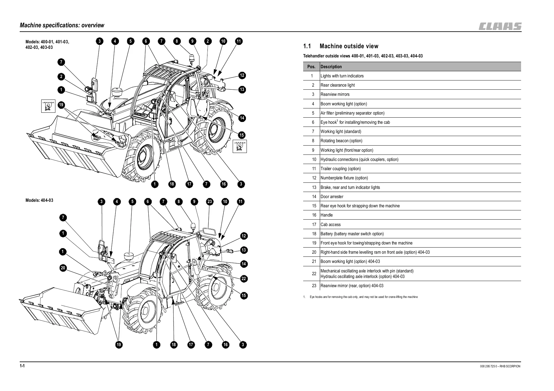
1.1 Machine outside viewp. 161.2 Inside of cab: overviewp. 171.3 Instrument panel, multifunctional lever, switch consoles: overviewp. 181.4 Important information on this manualp. 191.5 Model and trade names: overviewp. 191.6 Type labels and component numbersp. 201.7 Framep. 231.8 Enginep. 231.9 Oil/water cooling fanp. 241.10 Power trainp. 241.11 Axlesp. 251.12 Service and parking brakep. 261.13 Steering systemp. 261.14 Work hydraulicsp. 271.15 Electric systemp. 291.16 Tyres for models 400-01/401-03/402-03/403-03p. 331.17 Tyres for model 404-03p. 331.18 Weightsp. 341.19 Noise levelsp. 341.20 Vibrationp. 341.21 Coolant compound tablep. 341.22 Tightening torquesp. 351.23 Trailer couplings: trailer weight/drawbar loadp. 351.24 Payload: model 400-01 load diagramp. 361.25 Payload: models 401-03 load diagramp. 371.26 Payload: model 402-03 load diagramp. 381.27 Payloads: model 403 03 load diagramp. 391.28 Payloads: model 404 03 load diagramp. 401.29 Dimensions with bucketp. 441.30 Dimensions with pallet forksp. 45+3 Maintenance and servicing workp. 47
3.1 Explanation of symbols on the maintenance labelp. 483.2 Maintenance labelp. 493.3 Fluids and lubricants: overviewp. 503.4 Maintenance plan (overview)p. 513.5 Introductionp. 553.6 Safety prop for telescopic boomp. 553.7 Fuel systemp. 563.8 Engine lubrication system: maintenancep. 603.9 Maintenance of the engine and hydraulics cooling systemp. 643.10 Cleaning the radiator with the reversing fan (option)p. 693.11 Air filter maintenancep. 703.12 Maintenance: V-beltsp. 723.13 Gearbox and axle maintenancep. 733.14 Safety instructions regarding the hydraulic systemp. 783.15 Monitoring the hydraulic oil and the reflux filterp. 793.16 Checking the hydraulic oil levelp. 793.17 Filling up hydraulic oilp. 803.18 Replacing the reflux filter of the hydraulic systemp. 803.19 Replacing the microfilter of the hydraulic systemp. 803.20 Replacing hydraulic oilp. 813.21 Important information for the use of biodegradable oilp. 823.22 Checking hydraulic pressure linesp. 833.23 Lubrication workp. 843.24 Maintenance of the brake systemp. 873.25 Bleeding the hydraulic powerbrakep. 883.26 Replacing/bleeding the service brake fluid with bleed equipmentp. 893.27 Maintenance: compressed-air brake system (option)p. 913.28 Tyre maintenancep. 923.29 Heating and ventilation maintenancep. 943.30 Air conditioning (option): maintenancep. 953.31 Maintenance of the electric systemp. 983.32 Maintenance: trailer couplingp. 1023.33 General maintenance work on the machinep. 1033.34 Cleaning inside the cabp. 1043.35 Cleaning the seat beltp. 1043.36 Cleaning the exterior of the machinep. 1043.37 Checking screw connectionsp. 1043.38 Checking pivots and hingesp. 1043.39 Cleaning the engine compartmentp. 1053.40 Maintenance and servicing work “Aggressive Media”p. 1063.41 Maintenance and servicing of attachments on the quickhitchp. 108+4 Enginep. 109
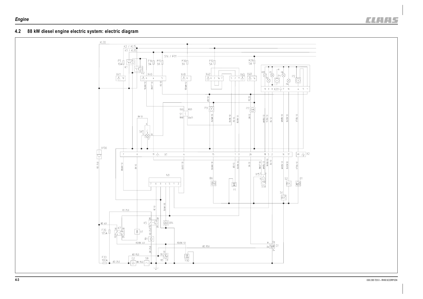
4.1 Electric system/hydraulics – fan: electric diagramp. 1104.2 88 kW diesel engine electric system: electric diagramp. 1124.3 103 kW diesel engine electric system: electric diagramp. 1144.4 Fuel preheater (option): electric diagramp. 1164.5 Diagnosis wiring diagramp. 1184.6 Fan: functional descriptionp. 1224.7 Fan connector assignment for models 402, 403, 404p. 1234.8 Diesel engine connector assignment (88 kW)p. 1244.9 Diesel engine connector assignment (103 kW)p. 1254.10 Fuel preheater connector assignmentp. 1264.11 Diagnosis connector assignmentp. 1274.12 Engine oil cooler side (88 kW): overviewp. 1294.13 Engine drive side (88 kW): overviewp. 1304.14 Engine turbocharger side (88 kW): overviewp. 1314.15 Engine oil cooler side (103 kW): overviewp. 1324.16 Engine drive side (103 kW): overviewp. 1334.17 Engine turbocharger side (103 kW): overviewp. 1344.18 Electronics overview (103 kW)p. 1354.19 Electronic engine revs setting (103 kW): overviewp. 1384.20 Function: warning telltale in tip switch (103 kW diesel engine)p. 1394.21 Engine drive – clutch (88/103 kW): overviewp. 1444.22 Fuel system (88/103 kW): overviewp. 1454.23 Bleeding the fuel system (88/103 kW)p. 1464.24 Fan circuit (not in reversing operation)p. 1474.25 Fan circuit with reversing fanp. 1484.26 Reversing valve blockp. 1494.27 Setting maximum fan revs (reversing fan)p. 1504.28 Setting maximum fan revs (without reversing fan)p. 1504.29 Cleaning the radiator with the reversing fan (option)p. 1514.30 Function: reversing fan operationp. 152+4.31 Workshop Manualp. 153
+RHB_Deutz_en_fr.pdf
+deutz_RHB_2012_03120361_a_komplett.pdf
Werkstatthandbuchp. 155Vorwortp. 157Inhaltsverzeichnisp. 161Technische Datenp. 162Ventilspieleinstellschemap. 173Ausgleichsscheibe ermittelnp. 195Bildzeichenerklärungp. 207Rüfen und Einstellenp. 211Demontage und Montagep. 241Bauteile ab- und anbauenp. 365Spezialwerkzeugp. 404+5 Power trainp. 419
5.1 40 kph drive hydraulics diagram for models 400 – 404p. 4205.2 40 kph drive electrics diagram for models 402, 403, 404p. 4225.3 20 kph hydraulic drive diagram for models 400 – 404p. 4245.4 Drive electrics diagram for models 400 – 404p. 4265.5 Functional despcription of drive hydraulics and electric systemp. 4315.6 Drive electrics connector assignment for models 400 – 404p. 4345.7 Towing and transporting the machinep. 4355.8 Hydraulic pump TMP 89 (models 402, 403, 404)p. 4375.9 Hydraulic pump H1 P078 (models 400, 401)p. 4385.10 High speed gearbox (0 – 40 kph)p. 4395.11 High speed gearbox with auxiliary motor (0 – 40 kph)p. 4395.12 Function without auxiliary motor (0 – 40 kph)p. 4405.13 Function with auxiliary motor (0 – 40 kph)p. 4405.14 Gearbox overview (0 – 40 kph)p. 4415.15 Overview of control cover and gearbox circuit diagram (0 – 40 kph)p. 4425.16 Control cover component parts for gearbox (0 – 40 kph)p. 4435.17 Hydraulic drive circuit (0 – 40 kph)p. 4445.18 Test report for models 400/401 (0 – 40 kph)p. 4455.19 Error description for test report models 400/401 (0 – 40 kph)p. 4465.20 Test report for models 402/403/404 (40 kph)p. 4475.21 Error description for test report models 402/403/404 (40 kph)p. 4485.22 Test report for models 403/404 (30 kph)p. 4495.23 Error description for test report models 403/404 (30 kph)p. 4505.24 Checking and setting boost pressure (0 – 40 kph gearbox)p. 4515.25 Checking high pressure (0 – 40 kph)p. 4525.26 Checking engine droop (pump) (0 – 40 kph)p. 4535.27 Checking driving direction identification (0 – 40 kph)p. 4545.28 Setting engine droop on the gearbox without auxiliary motor (0 – 40 kph)p. 4555.29 Setting engine droop on the gearbox with auxiliary motor (0 – 40 kph)p. 4565.30 Control initiation set screw (0 – 40 kph gearbox)p. 4575.31 Checking the cardan shaft speed (0 – 40 kph gearbox)p. 4585.32 Troubleshooting diagram (0 – 40 kph)p. 4595.33 Checking the differential pressure between M4 and M3 (0 – 40 kph)p. 4625.34 Evaluation: differential pressure measurement M4 (0 – 40 kph)p. 4635.35 Example: differential pressure measurement M4 (0 – 40 kph)p. 4645.36 Evaluation: differential pressure measurement M3 (0 – 40 kph)p. 4655.37 Example: differential pressure measurement M3 (0 – 40 kph)p. 4665.38 Cleaning the pressure relief valvep. 4675.39 Drive electronics Operator's Manual (SUSMIC)p. 4685.40 Error tablep. 4695.41 Checking proportional valve (1) energisation (0 – 40 kph)p. 4705.42 Table of electric current values of proportional valvesp. 4715.43 Checking the proportional valves by means of current measurementp. 4725.44 Exchanging proportional valves (0 – 40 kph)p. 4735.45 Interrupting the hydraulic pump/motor circuit (0 – 40 kph)p. 4735.46 Separating the consumer circuit from the hydraulic drivep. 4745.47 Checking control pressure M4/M5 (0 – 40 kph)p. 4755.48 Sealing work on the drive shaft (0 – 40 kph gearbox)p. 4765.49 Mounting the rotary shaft seal (0 – 40 kph gearbox)p. 4775.50 Mounting the drive flange (0 – 40 kph gearbox)p. 4785.51 Checking driving direction identification (0 – 40 kph gearbox)p. 4795.52 Removing driving direction identification (0 – 40 kph gearbox)p. 4805.53 Variable displacement motor 110 cm3/rev (20 kph)p. 4815.54 Variable displacement motor 110 cm3/rev (20 kph, seen from the side)p. 4825.55 Variable displacement motor 160 cm3/rev (20 kph)p. 4835.56 Test report for models 400 – 404 (20 kph)p. 4845.57 Error description for test report models 400/401 (20 kph)p. 4855.58 Hydraulic circuit: drive with hydraulic pump H1 P078 (20 kph)p. 4865.59 Hydraulic circuit: drive with hydraulic pump TMP 89 (20 kph)p. 4875.60 Setting boost pressure (20 kph)p. 4885.61 Checking high pressure (20 kph)p. 4895.62 Checking engine droop – variable displacement pump (20 kph)p. 4905.63 Setting engine droop – hydraulic motor (20 kph)p. 4915.64 Setting cardan shaft revs (20 kph)p. 492+6 Axles – differential lockp. 493
6.1 Differential lock diagrams (hydraulic/electric)p. 4946.2 Functional description of differential lockp. 4976.3 Differential lock connector assignmentp. 4986.4 20 kph gearbox: overviewp. 4996.5 Removing the 20 kph gearboxp. 5006.6 Installing the 20 kph gearboxp. 5076.7 Front and rear axle flangesp. 5156.8 Type label and oil filler neck: overviewp. 5176.9 Conversion table and tightening torquesp. 5186.10 Removing the joint housingp. 5196.11 Installing the joint housingp. 5216.12 Removing the double cardan shaftp. 5226.13 Installing the double cardan shaftp. 5246.14 Removing the planetary drivep. 5266.15 Replacing the seals of the planetary drivep. 5286.16 Installing the planetary drivep. 5296.17 Installing the planetary drivep. 5316.18 Sealing the front axle differentialp. 5336.19 Removing the front axle differential lockp. 5356.20 Installing the front axle differential lockp. 5386.21 Differential lock: hydraulic circuitp. 5416.22 Special tools: overviewp. 542+7 Brakesp. 549
7.1 Brake (20 kph) diagrams (electric/hydraulic)p. 5507.2 Brake (40 kph) diagrams (electric/hydraulic)p. 5527.3 Hydraulics diagram – trailer brake valvep. 5547.4 Functional description of brakesp. 5577.5 Brakes connector assignmentp. 5587.6 40 kph brake circuit: overviewp. 5597.7 20 kph brake circuit: overviewp. 5607.8 Disabling (releasing) the parking brake in the front axlep. 5617.9 Enabling (adjusting) the parking brake in the front axlep. 5617.10 Wear check: service brake discsp. 5627.11 Setting the brake linkage – master brake cylinderp. 5627.12 Service and parking brake: overviewp. 5637.13 Removing the brake discsp. 5647.14 Brake discs: overviewp. 5677.15 Installing the the brake pistons of the service and parking brakep. 5687.16 Installing the belleville spring washers and the brake cylinder housingp. 5697.17 Installing the service brakep. 5717.18 Towing and transporting the machinep. 5747.19 Hydraulic trailer brake circuit (option)p. 576+8 Steeringp. 577
8.1 Steering diagrams (electric/hydraulic)p. 5788.2 Functional description of steering systemp. 5818.3 Brakes connector assignmentp. 582+9 Work hydraulicsp. 583
9.1 Diagram: work hydraulics fixed displacement pump – raising/lowering the telescopic boomp. 5849.2 Diagram: work hydraulics variable displacement pump – raising/lowering the telescopic boomp. 5869.3 Electric diagram – raising/lowering the telescopic boom, load stabiliserp. 5889.4 Work hydraulics diagram – extending/retracting the telescopic boom, fixed displacement pumpp. 5909.5 Diagram: work hydraulics variable displacement pump – extending/retracting the telescopic boomp. 5929.6 Electric diagram – extending/retracting the telescopic boomp. 5949.7 Diagram: work hydraulics fixed displacement pump – dumping in/outp. 5969.8 Diagram: work hydraulics variable displacement pump – dumping in/outp. 5989.9 Electric diagram – dumping in/outp. 6009.10 Diagram: work hydraulics fixed displacement pump – locking/unlockingp. 6029.11 Diagram: work hydraulics variable displacement pump – locking/unlockingp. 6049.12 Electric diagram – locking/unlockingp. 6069.13 Diagram: work hydraulics fixed displacement pump – rear additional control circuitp. 6089.14 Diagram: work hydraulics variable displacement pump – rear additional control circuitp. 6109.15 Diagram: work hydraulics fixed displacement pump – rear additional control circuit – Autohitchp. 6129.16 Diagram: work hydraulics variable displacement pump – rear additional control circuit, Autohitchp. 6149.17 Diagram: work hydraulics fixed displacement pump – rear additional control circuit, Autohitch, tipping trailerp. 6169.18 Diagram: work hydraulics variable displacement pump – rear additional control circuit, Autohitch, tipping trailerp. 6189.19 Diagram: work hydraulics fixed displacement pump – rear additional control circuit, tipping trailerp. 6209.20 Diagram: work hydraulics variable displacement pump – rear additional control circuit, tipping trailerp. 6229.21 Diagram: work hydraulics fixed displacement pump – Autohitchp. 6249.22 Diagram: work hydraulics variable displacement pump – Autohitchp. 6269.23 Diagram: work hydraulics fixed displacement pump – Autohitch, tipping trailerp. 6289.24 Diagram: work hydraulics variable displacement pump – Autohitch, tipping trailerp. 6309.25 Diagram: work hydraulics fixed displacement pump – tipping trailerp. 6329.26 Diagram: work hydraulics variable displacement pump – tipping trailerp. 6349.27 Diagram: work hydraulics variable displacement pump – additional control circuit for quick couplers on telescopic boomp. 6369.28 Diagram: work hydraulics – safe load indicatorp. 6389.29 Electric diagram – front/rear additional control circuit for quick couplers, Autohitch, tipping trailer, front socket, safe load indicatorp. 6409.30 Diagram: work hydraulics variable displacement pump – additional control circuit for quick couplers on quickhitchp. 6429.31 Diagram: work hydraulics variable displacement pump – work platform with radio controlp. 6449.32 Work platform with radio control: electric diagramp. 6469.33 Tilt ram lock: electric diagramp. 6489.34 Diagram: work hydraulics variable displacement pump – frame levelling, oscillating axle interlockp. 6509.35 Frame levelling, oscillating axle interlock: electric diagramp. 6529.36 Functional description of work hydraulicsp. 6589.37 Work hydraulics connector assignmentp. 6629.38 Test report: models 400-01/401-01p. 6639.39 Test report: models 402-01/403-01p. 6649.40 Work hydraulics test portsp. 6659.41 Variable displacement pump (hydraulic pump)p. 6669.42 Checking and setting the work hydraulicsp. 6689.43 Work hydraulics circuit (gear pump)p. 6709.44 Work hydraulics circuit (variable displacement pump LS)p. 6719.45 Control valve connections (4-fold)p. 6729.46 Control valve (4-fold): overviewp. 6739.47 Control valve connections (5-fold)p. 6749.48 Control valve (5-fold): overviewp. 6759.49 Lift ram circuitp. 6769.50 Tilt ram circuitp. 6779.51 Compensating ram circuitp. 6789.52 Push-out ram circuitp. 6799.53 3rd control circuitp. 6809.54 Control valve (4-fold) pilot control circuitp. 6819.55 Valve block connections: overviewp. 6829.56 Pilot control unit, pilot valvep. 6839.57 Load stabiliserp. 6849.58 Load stabiliser circuitp. 6869.59 Changeover valve: Autohitch/tipping trailer connection/additional control circuitp. 6879.60 Autohitch, rear additional control circuitp. 6889.61 Tipping trailer connection circuitp. 6899.62 Front additional control circuitp. 6909.63 Frame levelling with oscillating axle interlock (option) telehandler 404: overviewp. 6919.64 Bleeding the hydraulic ram of the oscillating axle interlockp. 6949.65 Frame levelling circuitp. 6959.66 Frame levelling valve overviewp. 6969.67 Lift ram with hose burst valve: overviewp. 6979.68 Tilt ram: overviewp. 6989.69 Push-out ram with final position damping: overviewp. 6999.70 Compensating ram: overviewp. 6999.71 Quickhitchp. 7009.72 Installing the telescopic boomp. 7019.73 Replacing the control valvep. 7109.74 Replacing the priority valvep. 7109.75 Replacing the fan pumpp. 7119.76 Replacing the A 10 work hydraulics pumpp. 7129.77 Replacing the pilot valvep. 712+10 Electric systemsp. 713
10.1 Machine lights: electric diagramp. 71410.2 Turn indicators/horn/rotating beacon: electric diagramp. 71610.3 Mirror adjustment/heating: electric diagramp. 71810.4 Window wiper/washer, hydraulics monitoring: electric diagramp. 72010.5 Heating – air conditioning system/air-suspension seat: electric diagramp. 72210.6 Multimedia/cigarette lighter: electric diagramp. 72410.7 Functional description of hydraulics monitoringp. 72810.8 Hydraulics monitoring connector assigmentp. 72810.9 Lights connector assignmentp. 72910.10 Turn indicator/horn connector assignmentp. 73010.11 Rotating beacon connector assignmentp. 73110.12 Mirror adjustment connector assignmentp. 73110.13 Mirror heating connector assignmentp. 73110.14 Window wiper/wash connector assignmentp. 73210.15 Heating/air conditioning connector assignmentp. 73210.16 Air-suspension seat connector assignmentp. 73310.17 Multimedia connector assignmentp. 73310.18 Cigarette lighter connector assignmentp. 73310.19 Ohm's Law (current, voltage, resistance); powerp. 73510.20 Multifunction measuring devicep. 73510.21 Terminal descriptionp. 73610.22 Cable colour codingp. 74010.23 Fuses: overviewp. 74310.24 Electronic components: overviewp. 74710.25 Functional description of the steering electronicsp. 74910.26 Proportional controls: overview and connectionsp. 75110.27 Proportional electronicsp. 75210.28 Hold electronicsp. 75310.29 Wiring harness 1000103927 (joystick)p. 75310.30 Overview and functional check of safe load indicatorp. 75410.31 Safety instructions for the safe load indicatorp. 75810.32 Setting the safe load indicator (0 % point)p. 75910.33 Setting the safe load indicator (100 % point stability)p. 76010.34 Possible errors – safe load indicatorp. 76110.35 Retrofitting the front right and rear right working lightsp. 76210.36 Retrofitting a rotating beaconp. 76310.37 Retrofitting a radiop. 76410.38 Retrofitting the low-speed controlp. 76410.39 Retrofitting the air conditioning systemp. 76510.40 Retrofitting a front or rear socketp. 76610.41 Retrofitting a load stabiliserp. 76610.42 Wiring harness disconnect (cab – machine frame)p. 767+A Appendixp. 769
A .1 Hydraulics – 4-fold control valve: overall diagramp. 770A .2 Hydraulic fixed displacement pump – 5-fold control valve: overall diagramp. 772A .3 Hydraulic variable displacement pump – 5-fold control valve: overall diagramp. 774A .4 Machine components: overviewp. 775 - Work hydraulics
- Telescopic boom raising, lowering, extending and retracting circuits
- Tilt, quickhitch locking and additional control circuits
- Autohitch, tipping trailer and quick-coupler circuits
- Safe load indicator, work platform and radio-control circuits
- Frame levelling and oscillating axle interlock
- Hydraulic functional descriptions and connector assignments
- Test reports, test ports and hydraulic pump regulation
- Control valves, lift ram, tilt ram, compensating ram and push-out ram circuits
- Load stabiliser testing and adjustment
- Telescopic boom installation and hydraulic component replacement
- Electric systems
- Machine lighting, indicators, horn and rotating beacon diagrams
- Mirror, wiper, heating, air-conditioning and seat circuits
- Hydraulic monitoring and connector assignments
- Terminal descriptions, cable colour coding, fuses and relays
- Steering electronics and proportional controls
- Safe load indicator checks and settings
- Electrical retrofit procedures and wiring-harness connections
- Appendix
- 4-fold control valve hydraulic overall diagram
- Fixed-displacement pump 5-fold control valve overall diagram
- Variable-displacement pump 5-fold control valve overall diagram
- Machine components overview
- DEUTZ BFM 2012 Workshop Manual section
- Specification data and key to symbols
- Valve clearance, injector, compression-pressure and thermostat checks
- Control and adjustment procedures
- Complete-engine disassembly and reassembly
- Removal and re-installation of engine components
- Commercial and special tools
Taken together, these sections provide a technician with both system-level understanding and task-level repair information. Schematics show how hydraulic and electrical circuits are connected, component overviews help locate service points, test values support diagnosis, and removal or installation sequences provide the procedural detail needed for deeper mechanical work.
Diagnostics, Diagrams and Repair Procedures
This CLAAS Scorpion repair manual is particularly useful where a fault cannot be resolved with routine maintenance alone. The power-train section includes pressure testing, drive test reports, error descriptions, proportional-valve checks and troubleshooting. The engine section contains diagnosis wiring and flash-code information for the 103 kW configuration, including fault listings for sensors, injectors, rail pressure, oil pressure, coolant temperature, charge-air temperature and other monitored functions.
Work-hydraulic coverage is extensive, with separate circuits for boom lift, extension, tilt, quickhitch operation, additional control circuits, load stabilisation, frame levelling and optional equipment. Electrical coverage includes component positions, connector assignments, fuse and relay information, steering electronics, safe load indicator checks and machine wiring diagrams. This combination makes the manual useful for tracing a fault from the electrical command side through hydraulic control and into the mechanical component being operated.
Repair and Service With the Correct Technical Reference
The CLAAS Scorpion 9040 7045 7040 7030 6030 Telehandler Repair Manual supports routine servicing, fault diagnosis, hydraulic and electrical testing, component adjustment, brake and axle work, hydrostatic-drive checks, telescopic-boom repairs, engine-related work and major component removal or installation. Having the specified pressures, capacities, tightening data, wiring paths, hydraulic circuits and step-by-step procedures available during a repair helps avoid relying on approximate settings or incomplete service information.
Delivered as an instant PDF after payment, there is no physical book and no shipping delay. Open the manual on a computer, tablet or phone, keep it available beside the machine during diagnosis and repair, and print the pages you need for workshop use.


Reviews
There are no reviews yet.